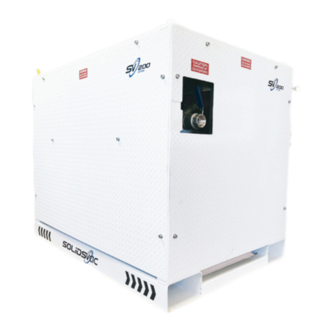
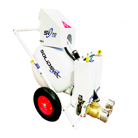
SOLIDSVAC SV10-AIR FOX User manual

CONTENTS
Description
Safety First
1. Operation Overview
2. Technical Data
3. Pump Set-Up
4. Operation
5. Maintenance
6. Job Safety Analysis
Page
3
3
4
5
6
10
15
Scan this QR Code for an electronic version of this Operations
Manual

www.solidsvac.com
page 3
SAFETY FIRST
CAUTION & GENERAL SAFETY
This manual contains important information concerning the installation, operation and maintenance of the Solidsvac Pump, Model
SV10-Airfox. To prevent injury to personnel or equipment damage, this manual MUST be read and understood by those responsible for
the installation, operation and maintenance of the equipment.
THIS OPERATION MANUAL MUST BE USED IN CONJUNCTION WITH BOTH SITE-SPECIFIC RA AND JSA’s.
-Isolate, tag out and disconnect the air supply to the unit prior to working on any part of the system
-Lift the equipment correctly using correct manual handling techniques and only at the lifting points provided
-The pump should be installed in a safe level area, which provides adequate access for operating the equipment
-Ensure all hoses are in good condition, correctly rated and certified for the service in which they are to be used
-Inspect the unit regularly for damaged or worn components
-All covers MUST be fitted prior and during operation
-Air pressure should NEVER exceed rated pressure
-Tie down points (if fitted) MUST NOT be used as lifting point
CAUTION: BE AWARE OF RETAINED MATERIAL IN THE TANK INCREASING WEIGHT
SOLIDSVAC PUMPS EACH HAVE SPECIFIC COMPRESSED AIR REQUIREMENTS DEPENDING ON THE JET PACK FITTED.
The operator MUST ensure that an appropriate and adequate air supply is available depending on the model and Jet Pack in use.
All Solidsvac Pumps require a minimum operating pressure of 500kPa and have a maximum operating pressure of 720kPa
(105psi). It is recommended that a 25mm (1”) i.d. air hose is used for compressed air supply to the pump.
The Discharge hose MUST be no smaller in diameter than the pumps outlet 25mm (1”) preferably a self-supporting type and secured
at regular intervals.
WARNING: THE PUMP-OUT LINE MUST BE SECURED AT THE EXIT POINT
1. OPERATIONAL OVERVIEW
The Solidsvac SV10-AIR FOX operates as a shuttle system
alternately loading via vacuum and discharging via pressure
a wide range of flowable and semi-flowable materials.
Operation is fully automatic and the Solidsvac SV10-AIR FOX
features no internal workings withpressure discharge. Place
unit in desired location and Do not submerge over red line
unit fill as level of water rises and discharge up to 80m
WARNING
Compressed air can be dangerous. Correctly rated hoses and
piping should be used in conjunction with the appropriate
fittings and safety devices on all connections.

page 10
3. PUMP SET-UP
Before commencing operation, Solidsvac strongly recommends each user reads the Operation Manual supplied with each unit and
available on line or via the QR code on pump.
Note: No training is necessary to operate the SV10-AIR FOX however understanding the Operations Manual is essential to safe
practice.
Solidsvac also recommends that a site-specific Risk Assessment (RA) of the pumping operation is undertaken. Any recommendations
arising from the Risk Assessment would be additional to the following:
-The unit and all hoses and fittings are undamaged and in good working order.
-Hoses MUST be fit for purpose and appropriate for explosive atmospheres. For example bonded or FRAS hose.
-The compressor in use MUST be installed in a safe area.
-All covers are fitted in place and correctly secured.
-Clean compressed air at minimum working pressure of 500kPa (75 psi) at 100 cfm is available.
-A 25mm (1”) i.d. air hose is available.
-The correct PPE is available and worn for operating compressed air equipment
-Eye Protection
-Hearing Protection
-Gloves
-Safety Boots
4SV10- AIR FOX INSTALLATION STEPS
1. Connect compressed air line to unit (1/2-1” airline) ensure safety clips, whip checks etc. are fitted
2. Connect discharge line to unit (1” line) this line may need to be restrained due to movement during discharge
3. Attach both suction and discharge hoses along with any accessories as required and ensure safety clips are in place.
4. Lower pump into water but DO NOT SUBMERG PAST RED LINE.
5. Turn on air valve and pump will start operating.
6. The pump is now ready for use.
Do not submerge below red line

page 10
CONTENTS EXCLUDED FOR PUMPING
Solidsvac recommends that any contents the fall within the scope of the below class liquids should not be pumped with any Solidsvac
unit. Solidsvac also recommend that a site-specific JSA should be conducted with reference to any other type of material being
pumped.
7. Class IIIA liquids with a flash point equal to or greater than 140 °F (60 °C), but less than 200 °F (93 °C) have a NFPA
704 flammability rating of 2.
8. Class IIIB liquids with a flash point equal to or greater than 200 °F (93 °C) have a NFPA 704 flammability rating of 1.
OPERATING PARAMETERS
The Solidsvac SV10-AIR FOX can operate within environments ranging from 0 °C to 50 °C and all
humidity. The maximum medium temperature allowable for the SV10-AIR FOX is 50 °C.
HOSES
Solidsvac recommends the hoses (Air Supply, Discharge) used in operation with the SV10-AIR FOX are to be made of anti-static
material. If the hoses used in operation with the SV10-AIR FOX are not made of anti-static material, they MUST be braided to comply
with requirements for Fire Resistance & Anti-Static (FRAS) to AS/NZS 2660, or other equivalent standard.
.

page 10
4. OPERATION
Turn the air supply valve ON at the source. Turning the pump valve to ON, the pump will now commence its cycle of operation. This
involves the unit allowing water to enter a vessel till it reaches a certain level at that time the unit will dispel the water and then go
back to the fill cycle. The unit will continually move between each of these cycles filling/discharging.
Important!!!!!! not to place unit in water that covers the red line on body of unit
Once pumping is completed, remove the suction from the material and allow the pump to cycle self clean. On completion of the
operations, isolate the air supply and allow the pump to cycle until the supply in the line is exhausted, then turn the pump off at the
supply line. SOLIDSVAC recommends checking the pump discharge to ensure it remains correctly anchored at the exit.
Lubrication is not required during operation.
Note: Dry operation will not damage the pump.

page 10
5.MAINTENANCE
In use, the Solidsvac SV10-AIR FOX requires little to no maintenance, however Solidsvac recommends that the following strict measures
are taken to ensure pump remains in good working order.
Maintenance, repairs, and the disassembling of the unit can be carried out by any qualified Fitter with a basic knowledge of
pneumatics.
SERVICE TIPS
-Set up a maintenance schedule and follow it diligently.
-Clean the machine areas before removing pneumatic components.
Note: When steam cleaning or using water to clean a machine, be sure that filler openings, breather caps etc are protected
from possible entry of water into the system.
-Use clean plastic plugs to cover the ends of disconnected lines or to plug openings when working on a pneumatic system.
-A clean workbench is an absolute ‘MUST’ when servicing components. An industrial-type vacuum cleaner is a valuable aid
in removing dust, dirt and tiny metal particles from the work area.
-Check the condition of your tools – they should be clean. Always use hammers made of plastic or leather, so there is no
danger of metal chips getting into components.
-When removing parts for service, clean them and then store them in plastic bags or other clean containers until they are
installed again.
-When cleaning pneumatic parts, use extreme care to ensure that the cleaning fluid is non-flammable and compatible with the
system.
-Use common-sense precautions to prevent dirt entering components that have been temporarily removed from the circuit.
SYSTEM PERFORMANCE
Pneumatic problems that affect system flow and pressure are not always easy to locate. The system testing procedure described later
in this section is based on a useful step-by-step approach to troubleshooting. Troubleshooting charts make the fault-finding process
easier and faster.
EFFECTS OF A DROP IN SYSTEM FLOW RATE
-A pressure drop will affect the speed and cycle times of a pneumatic machine; actuators will not extend, retract, or rotate at
the required speed. Actuator control will become jerky with inconsistencies in flow as cylinders and motors are supplied at
different rates. In many complex pneumatic systems, the sequencing and positioning of component operations will be affected
as cycle times become thrown out of programmed control.
-The compressor’s discharge flow rate should be checked first to ensure that the drop in flow is not a problem of internal
leakage or incorrect setting of compressor controls.
EFFECTS OF DROPS IN PRESSURE
The major causes of pressure drop include:
-Pipework restrictions (for example, incorrect sizing) fitting restrictions and sharp corners
-Incorrect pressure settings
-Sudden enlargement in fluid conductors
-Long lengths of fluid conductors
-Component leakage (internal and external)
-Broken valve springs
-Blocked or crimped air lines
-Loose fittings
-Valves not sealing correctly because of contaminants
-Some combination of the above causes

page 10
SYSTEM TESTING PROCEDURES
Pneumatic systems, like all machines, require routine maintenance to ensure reliability. However, there are still times when problems
occur and MUST be located quickly and efficiently, especially in production applications. A step-by-step method has been devised as
a way of finding and solving pneumatic problems quickly.
These steps are as follows:
STEP 1: KNOW THE SYSTEM -
Study the machine’s technical specifications to obtain an understanding of how the system operates and the function of the
machine’s components. Obtain a circuit drawing and check the system through. Check the machine’s maintenance records
and commissioning test results if they are available.
STEP 2: ASK THE OPERATOR -
Determine the symptoms of the problem by asking the operator for a detailed description of the machine’s normal operating
performance.
STEP 3: INSPECT THE MACHINE -
Use your senses (touch, smell, sight, and hearing) to locate problems or damage such as noisy components, air leaks, malfunctioning
components, and damaged air lines.
STEP 4: OPERATE THE MACHINE -
Operate the machine and check that the machine’s gauges are reading ‘normal’ and that there are no unusual noises. The operation
of the machine’s controls should not be ‘sticky’ or ‘spongy’. The machine’s performance should not be slow, erratic – or non-existent.
STEP 5: LIST THE POSSIBLE CAUSES -
Once the fault has been located and recognised, list the possible causes – starting with the simplest.
STEP 6: REACH A CONCLUSION -
Use a troubleshooting chart to check the list of possible causes; then decide which is the most likely.
Note: 99% of all issues are air supply related.

page 10
SYSTEM MAINTENANCE
A pneumatic system is easy to maintain. However, like any other mechanism, it MUST be operated and maintained correctly.
Pneumatic systems can be damaged by excessive pressures, fluid contamination and by high operating temperatures.
Regular maintenance will reduce your pneumatic troubles. By using a regular maintenance programm(preventative maintenance) to
care for a system, you can eliminate common problems and anticipate special ones. Problems can be corrected or averted before a
breakdown occurs.
The following are the key problems that commonly need to be addressed in pneumatic maintenance:
-Water-contaminated air
-Poor air filtration
-Incorrect pressure settings
-Incorrect lubricator settings, resulting in sticking valves
-High air temperature
-Loose supply lines
-Faulty seals
IMPORTANCE OF CLEANLINESS
Cleanliness is of supreme importance when it comes to servicing pneumatic systems. Keep dirt and other contaminants out of the
system. Small particles can score valve, cause seizing of components and clog orifices, resulting in expensive repair jobs.
When servicing a pneumatic system, always do the following to ensure cleanliness:
-Keep the compressor and machine's lubricating oil clean
-Keep the system clean
-Keep your work area clean
-Be careful when you change seal or components (take photos)
-Use caution with compressed air
-Ensure all pneumatic components supply lines are secure
SAFETY FIRST
PRIOR TO COMMENCING ANY WORK ON THE UNIT, THE AIR SUPPLY VALVE MUST BE
ISOLATED AND THE CONTROL SYSTEM TESTED DEAD

PUMP PREVENTATIVE
MAINTENANCE PROGRAM
The following is the work to be performed to a SV10-AIR FOX Pump during Preventative Maintenance
Check. All items, except annual checks (Tradesman), are to be carried out by a Competent Operator.
-Lock and tag out equipment
-Record equipment data
-Check all mounting bolts and clamps are secure and tight
-Check vessel support frame and wheels for soundness
-Visual inspection of pump for any damage
-Check exhaust box for cleanliness (if fitted)
-Check condition of seals
-Check 2 way ball valve for leakage
-Inspect condition of airlines and fittings
-Check operation posi-check valve (if fitted)
-Test the operation of the SV10-AIR FOX pump prior to returning to service
-Make note on the field report of any findings that may require additional work
email info@solidsvac.com

PUMP MAINTENANCE CHECKLIST
DESCRIPTION
COMMENT
MAINTENANCE FREQUENCY
DAILY WEEKLY MONTHLY ANNUALLY
Pump Check all guards are in place and valves are working.X
Overall visual
inspection
Complete overall visual inspection to be sure all
equipment is operating and guarding are in place.
X
Check ball valve
seals Assure that all seals are in good condition and not
worn, split or damaged.
X
Check airlines and
fittings
Inspect airlines for any deterioration, check fittings for
cracks and leaking.
X
Check bolts Check and secure all clamps and bolts.
X
Check control
system
Conduct a full service on the pump
X
www.solidsvac.com

JOB SAFETY
ANALYSIS
Note: It is recommended that a site-specific JSA is conducted prior to operation of the
unit.

JOB SAFETY ANALYSIS
SOLIDSVAC SV10-AIR FOX
Date Of Audit – June 2020.
Equipment/Task: Set-up and operate Solidsvac Solids/Slurry Pump.
Note: Site Safety requirements MUST be adhered to at all times. Personal Protective Equipment including approved safety eyewear
and hearing protection are to be worn at all times whilst operating this equipment.
STEP # JOB STEPS HAZARDS/WHAT CAN GO WRONG CONTROLS & RISK REDUCTION
1Selecting the right pump.
Selecting the incorrect pump/
equipment to transfer media that is
either hazardous in itself or becomes
hazardous when transferring can
result in delay of operating and injury.
Site-specific JSA MUST be conducted prior
to operation to identify site-specific media
risks & hazards.
2Siting the pump. The pump may be unstable. Site the pump on a reasonably flat, level
&stable surface, or on asuitable
straddle frame. DO NOT SUBMERG PAST
RED LINE
3Connecting discharge hose
range to pump.
(a) Use of inappropriate non pressure
rated discharge hose, hose or couplers
may cause discharge hose range
failure.
Ensure minimum 1” discharge range is
used rated to 10Bar. Hose may be rubber
or poly. The pump utilises the claw
coupling system. Use hose restraints
(safety clips, whip checks etc.)
(b) Sharp bends, tee pieces and
valves in a discharge line can cause
blockages.
Ensure discharge hose range has no
sharp bends or tee pieces and is free of
restrictions such as reductions in hose
diameter or gate valves etc.
(c) Discharge hose range may move
particularly at discharge exit point.
Ensure discharge hose range is secured
at appropriate points along its length and
particularly at discharge exit point.
4Connecting the air supply hose
to the pump. Air hose should be
blown clean before connection.
(a) Compressed air can be dangerous
and may cause injury. Blowing air
supply hose clean can cause eye,
hearing or physical injury if not carried
out in a controlled manner.
Ensure air hose is turned off completely
and that the pump air inlet ball valve is
closed before connection.
(b) Air supply hose can ‘fly off’ if not
properly connected.
Ensure air line couplings are correctly
engaged and have safety clips fitted.

JOB SAFETY ANALYSIS
SOLIDSVAC SV10-AIR FOX
Date Of Audit – June 2020.
Equipment/Task: Set-up and operate Solidsvac Solids/Slurry Pump.
Note: Site Safety requirements MUST be adhered to at all times. Personal Protective Equipment including approved safety eyewear
and hearing protection are to be worn at all times whilst operating this equipment.
STEP # JOB STEPS HAZARDS/WHAT CAN GO WRONG CONTROLS & RISK REDUCTION
7Pump Operation – Unblocking
Discharge Hose Range Blockages.
Pressure in discharge range has
potential to cause eye and physical
injury.
STOP THE PUMP. DO NOT DISCONNECT
ANY DISCHARGE HOSE RANGE
COMPONENT WHILST PUMP IS
OPERATING. Depressurise the discharge
hose range by operating a manual
pressure relief valve on the pump or
within the hose range (if fitted) OR, using
EXTREME CAUTION, loosen hose couplings
upstream of the estimated blockage point
(ie. between pump and blockage) to safely
vent residual pressure before attempting to
fully open hose joints to clear the blockage.
8Pump Operation – Discharge
Hose Range Exit Point. Injury can be caused by high velocity
material ejected from discharge point.
Ensure end of 1” discharge line is secured
9Disconnecting Pump from Air
Supply. Injury may result from uncontrolled
whipping of pressurised air hose.
Before disconnecting air hose isolate it
upstream & open the Pump Air Supply Ball
Valve to release residual pressure from the
air line.
telephone +61 456 000 665
email info@solidsvac.com
Table of contents
Other SOLIDSVAC Water Pump manuals
Popular Water Pump manuals by other brands

GORMAN-RUPP PUMPS
GORMAN-RUPP PUMPS 4D-X3 3P Installation, operation, and maintenance manual with parts list

OLIJU
OLIJU SFI Installation and operation instructions

Intex
Intex AP619RL owner's manual

Trotec
Trotec TGP 1025 ES operating manual

Agilent Technologies
Agilent Technologies DS40M user manual

Royalbeach
Royalbeach 20182 instruction manual