SOLIDSVAC SV70-SPDK User manual
SV70-SPDK Operations Manual
ISSUED DATE - 140421 LAST REVISED - 050821
SOLIDS PUMPING SYSTEMS
V 1.3
U1/ 5-7 Boeing Place - Caboolture - QLD 4510 - Australia

CONTENTS
Description
Safety First
1. Operation Overview
2. Design Registration
3. Technical Data
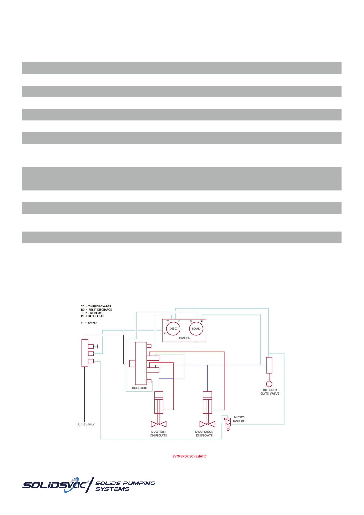
4. Schematic
5. Pump Set-Up
6. Operation
7. Maintenance
8. Timer Cycling & Adjustments
9. Accessories
10. Operation Risk Assessment
11. Parts Assembly
12. Job Safety Analysis
Page
3
3
3
4
4
5
6
7
11
12
13
21
24
Scan this QR Code for an electronic version of this Operations Manual

www.solidsvac.com
page 3
SAFETY FIRST
CAUTION & GENERAL SAFETY
This manual contains important information concerning the installation, operation and maintenance of the Solidsvac Pump, Model
SV70-SPDK. To prevent injury to personnel or equipment damage, this manual MUST be read and understood by those responsible for
the installation, operation and maintenance of the equipment.
THIS OPERATION MANUAL MUST BE USED IN CONJUNCTION WITH BOTH SITE-SPECIFIC RA AND JSA’s.
- Isolate, tag out and disconnect the air supply to the unit prior to working on any part of the system
- Lift the equipment only at the lifting points provided
- The pump should be installed in a safe level area, which provides adequate access for operating the equipment
- Ensureallhosesareingoodcondition,correctlyratedandcertiedfortheserviceinwhichtheyaretobeused
- Inspect the unit regularly for damaged or worn components
- AllcoversMUSTbettedpriorandduringoperation
- Air pressure should NEVER exceed rated pressure
- Tiedownpoints(iftted)MUSTNOTbeusedasliftingpoint
CAUTION: BE AWARE OF RETAINED MATERIAL IN THE TANK INCREASING WEIGHT
SOLIDSVAC PUMPS EACH HAVE SPECIFIC COMPRESSED AIR REQUIREMENTS DEPENDING ON THE JET PACK FITTED.
The operator MUST ensure that an appropriate and adequate air supply is available depending on the model and Jet Pack in use.
AllSolidsvacPumpsrequireaminimumoperatingpressureof500kPaandhaveamaximumoperatingpressureof720kPa(105psi).
Itisrecommendedthata25mm(1”)i.d.airhoseisusedforcompressedairsupplytothepump.
Note: An 18mm (¾”) i.d. Air hose contains HALF the volume of the recommended 25mm (1”) hose.
TheDischargehoseMUSTbenosmallerindiameterthanthepumpsoutlet75mm(3”)preferablyaself-supportingtypeandsecured
at regular intervals.
WARNING: THE PUMP-OUT LINE MUST BE SECURED AT THE EXIT POINT
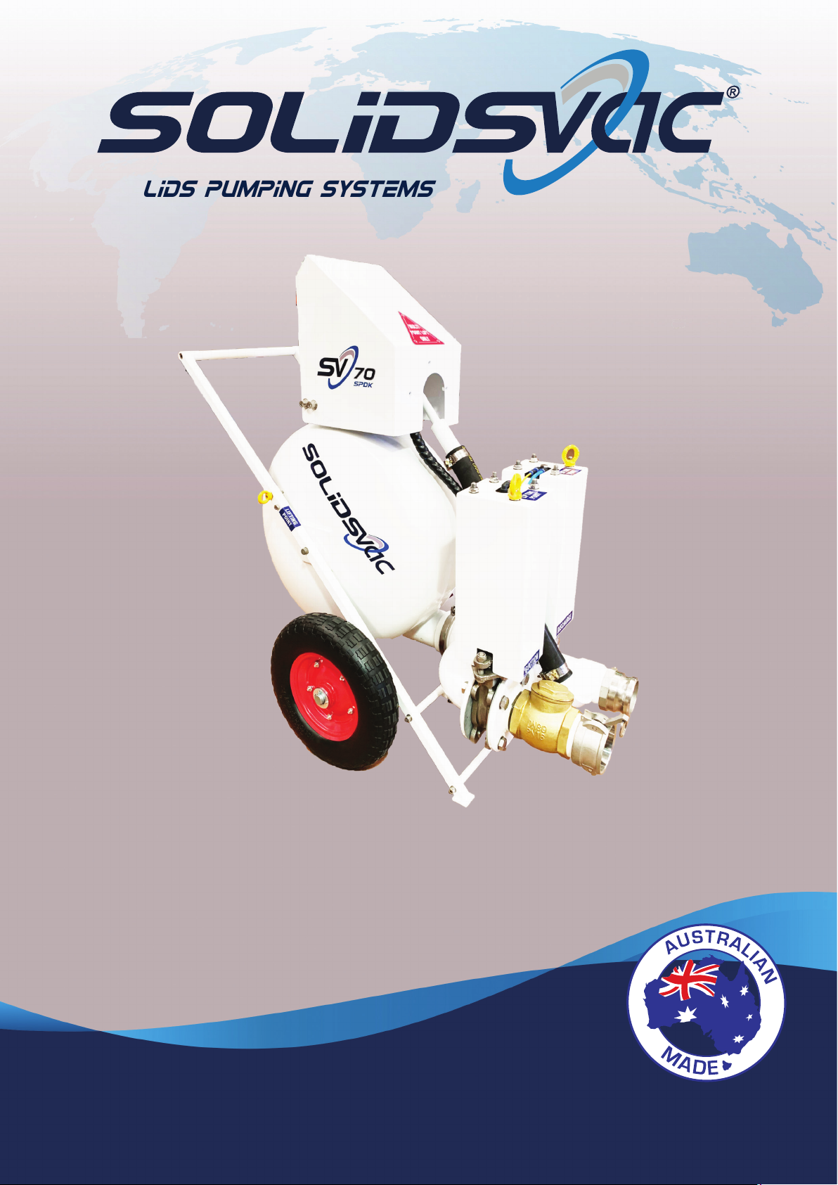
1. OPERATIONAL OVERVIEW
The Solidsvac SV70-SPDK operates as a shuttle system
alternately loading via vacuum and discharging via pressure
awiderangeofowableandsemi-owablematerials.
Operation is fully automatic and the Solidsvac SV70-SPDK
features no internal workings, high vacuum and pressure
discharge where suction of up to 50 metres and discharges in
excess of 400 metres are achievable.
WARNING
Compressed air can be dangerous. Correctly rated hoses and
piping should be used in conjunction with the appropriate
ttingsandsafetydevicesonallconnections.
Theunitisnotdesignedtooperateabove758kPa(114psi)and
thePRVwillrelieveat758+/-35kPa(110psi+/-5psi).
2. DESIGN REGISTRATION
TheSolidsvacSV70-SPDKhasaCerticateofPlantDesign
Registration from Workcover NSW, Australia. A copy of which
may be obtained by contacting Solidsvac Pumps.
DESIGN REGISTRATION # PV-6-198163/16
Technical Standards
- AS2971-2007 Serially Produced Pressure Vessels
- AS4343-2005 Pressure Equipment - Hazard Levels
- AS1210-1210 Pressure Vessels
telephone +61 456 000 665
email [email protected]
page 4
3. TECHNICAL DATA
4. SV70-SPDK SCHEMATIC
Height 1150 mm 45”
Width 650 mm 25.5”
Length 1240 mm 48.5”
Weight 130 kg 264 lb
Air inlet 13 mm 1/2” BSP
Suction inlet 75 mm 3”
Discharge outlet 75 mm or 100 mm 3” or 4”
Suction lift 7.9m @ 100 cfm
9.2m @ 180 cfm
11.5m @ 230 cfm
26' 2" @ 100 cfm
30' @ 180 cfm
37' 7" @ 230 cfm
Air consumption options 2.8 m3/Min Jet Pack
5.0 m3/Min Jet Pack
6.5 m3/Min Jet Pack
100 cfm Jet Pack
180 cfm Jet Pack
230 cfm Jet Pack
Delivery 400+ m 1312+ ft
Displacement cycle 65 ltr 17 gal
Operating pressure 7bar(max)@690kPa
4.5bar(min)@448kPa 100psi(max)
65psi(min)
Maximum solids 50 mm 2”
Measured water throughput 400 lpm 106 gpm
TECHNICAL DATA METRIC US IMPERIAL

www.solidsvac.com
page 5
5. PUMP SET-UP
Before commencing operation, Solidsvac strongly recommends each user reads the Operation Manual supplied with each unit and
available online or via the QR code on pump.
Note: No training is necessary to operate the SV70-SPDK however understanding the Operations Manual is essential to safe
practice.
Solidsvacalsorecommendsthatasite-specicRiskAssessment(RA)ofthepumpingoperationisundertaken.Anyrecommendations
arising from the Risk Assessment would be additional to the following:
- Theunitandallhosesandttingsareundamagedandingoodworkingorder.
- Allcoversarettedinplaceandcorrectlysecured.
- Cleancompressedairatminimumworkingpressureof690kPa(100psi)isavailable.
- A25mm(1”)i.d.airhoseisavailable.
- The discharge area has suitable warnings to protect personnel.
- The correct PPE is available and worn for operating compressed air equipment
- Eye Protection
- Hearing Protection
- Gloves
- Safety Boots
- Set the Solidsvac Pump in a safe level location as close to the material to be pumped as possible.
- Attach both suction and discharge hoses along with any accessories as required and ensure safety clips are in place.
- Ensurethemainairvalveisintheoffpositionandattachthe25mm(1”)airhosetotheSolidsvacPump&tsafetyclips.
- The pump is now ready for use.
Note: Always position hoses out of walkways where possible remaining aware of trip and fall hazards.
CONTENTS EXCLUDED FOR PUMPING
Solidsvac recommends that any contents that fall within the scope of the below class liquids should not be pumped with any
Solidsvacunit.Solidsvacalsorecommendsthatasite-specicJSAshouldbeconductedwithreferencetoanyothertypeofmaterial
being pumped.
- ClassIIIAliquidswithaashpointequaltoorgreaterthan140°F(60°C),butlessthan200°F(93°C)haveaNFPA704
ammabilityratingof2.
- ClassIIIBliquidswithaashpointequaltoorgreaterthan200°F(93°C)haveaNFPA704ammabilityratingof1.
OPERATING PARAMETERS
TheSolidsvacSV70-SPDKcanoperatewithinenvironmentsrangingfrom0°Cto50°Candallhumidity.
ThemaximummediumtemperatureallowablefortheSV70-SPDKis50°C.
HOSES
Solidsvacrecommendsthehoses(AirSupply,Suction,Discharge)usedinoperationwiththeSV70-SPDKaretobemadeofanti-static
material. If the hoses used in operation with the SV70-SPDK are not made of anti-static material, they MUST be braided to comply with
requirementsforFireResistance&Anti-Static(FRAS)toAS/NZS2660,orotherequivalentstandard.
EARTHING POINT
AllSolidsvacmodelsarettedwithanEarthingPointwhichismandatoryrequirementpriortooperation.Solidsvacstrongly
recommends that the operator takes the necessary measures to earth the unit prior to operation.
WARNING: TO AVOID POSSIBLE ELECTROSTATIC CHARGES PRODUCED BY THE MATERIAL CONVEYED THE
OPERATOR MUST EARTH THE UNIT PRIOR TO OPERATION.
telephone +61 456 000 665
email [email protected]
page 6
6. OPERATION
Turn the air supply valve ON at the source. Turning the pump valve to ON, the pump will now commence its cycle of operation. The
LOAD and DISCHARGE cycles are controlled by adjustable pneumatic timers, these allow for adjusting the pump to varying conditions,
i.e.heavyorlightmaterialorlongorshortdistancesetc.DuringtheLOADcycletheoperatorshouldnoteanaudibledifference(Gargle)
oncethevesselhaslled,adjusttheLOADtimertowherethecyclecompletesjustasorpriortothisoccurring.TheDISCHARGEcycle
depends on both the material being transferred and the distances involved. A discharge setting of 4-6 seconds will accommodate
about 95% of most pumping jobs with the SV70-SPDK.
Once pumping is completed, remove the suction from the material and allow the pump to cycle self-clean, on completion of the
operations isolate the air supply and allow the pump to cycle until the supply in the line is exhausted, then turn the pump off at the
supply line. SOLIDSVAC recommends checking the pump discharge to ensure it remains correctly anchored at the exit. Lubrication is
not required during operation.
Note: Dry operation will not damage the pump.
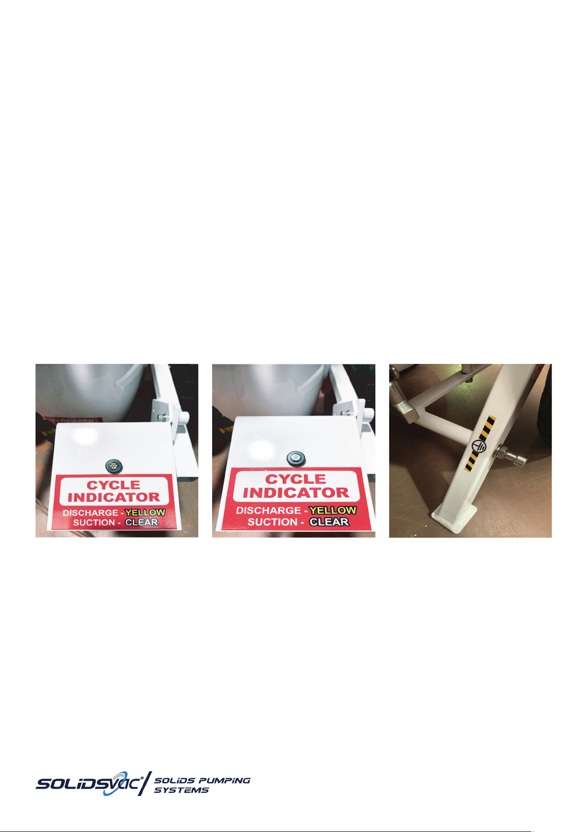
CYCLE INDICATOR
Thepumpisttedwithanindicatortoinformtheoperatorwhichcyclethepumpisoperatingin,wheninthedischargecyclethe
indicator is yellow and when in the suction cycle the indicator is clear.
Note: If the pump is supplied with a head of pressure it is possible for the pump to siphon when the air supply is turned off. To
prevent siphoning when the pump is not in operation, turn the pump off when it is in the discharge cycle or isolate the material
supply source to the pump.
DISCHARGE CYCLE INDICATED SUCTION CYCLE INDICATED EARTHING POINT
An earthing point is tted to the
SV70-SPDK if required by the site-
specic RA or JSA.

www.solidsvac.com
page 7
7. MAINTENANCE
In use, the Solidsvac SV70-SPDK requires little to no maintenance, however Solidsvac recommends that the following strict measures
are taken to ensure pump remains in good working order.
Maintenance,repairs,andthedisassemblingoftheunitbecarriedoutbyanyqualiedFitterwithabasicknowledgeofpneumatics.
SERVICE TIPS
- Set up a maintenance schedule and follow it diligently.
- Clean the machine areas before removing pneumatic components.
Note: When steam cleaning or using water to clean a machine, be sure that ller openings, breather caps etc are protected
from possible entry of water into the system.
- Use clean plastic plugs to cover the ends of disconnected lines or to plug openings when working on a pneumatic system.
- A clean workbench is an absolute ‘MUST’ when servicing components. An industrial-type vacuum cleaner is a valuable aid in
removing dust, dirt and tiny metal particles from the work area.
- Check the condition of your tools – they should be clean. Always use hammers made of plastic or leather, so there is no danger
of metal chips getting into components.
- When removing parts for service, clean them and then store them in plastic bags or other clean containers until they are
installed again.
- Whencleaningpneumaticparts,useextremecaretoensurethatthecleaninguidisnon-ammableandcompatiblewiththe
system.
- Use common-sense precautions to prevent dirt entering components that have been temporarily removed from the circuit.
SYSTEM PERFORMANCE
Pneumaticproblemsthataffectsystemowandpressurearenotalwayseasytolocate.Thesystemtestingproceduredescribedlater
inthissectionisbasedonausefulstep-by-stepapproachtotroubleshooting.Troubleshootingchartsmakethefault-ndingprocess
easier and faster.
EFFECTS OF A DROP IN SYSTEM FLOW RATE
- A pressure drop will affect the speed and cycle times of a pneumatic machine; actuators will not extend, retract, or rotate at
therequiredspeed.Actuatorcontrolwillbecomejerkywithinconsistenciesinowascylindersandmotorsaresuppliedat
different rates. In many complex pneumatic systems, the sequencing and positioning of component operations will be affected
as cycle times become thrown out of programmed control.
- Thecompressor’sdischargeowrateshouldbecheckedrsttoensurethatthedropinowisnotaproblemofinternal
leakage or incorrect setting of compressor controls.
EFFECTS OF DROPS IN PRESSURE
The major causes of pressure drop include:
- Pipeworkrestrictions(forexample,incorrectsizing)ttingrestrictionsandsharpcorners
- Incorrect pressure settings
- Suddenenlargementinuidconductors
- Longlengthsofuidconductors
- Componentleakage(internalandexternal)
- Broken valve springs
- Blocked or crimped air lines
- Loosettings
- Valves not sealing correctly because of contaminants
- Some combination of the above causes

telephone +61 456 000 665
email [email protected]
page 8
SYSTEM TESTING PROCEDURES
Pneumatic systems, like all machines, require routine maintenance to ensure reliability. However, there are still times when problems
occurandMUSTbelocatedquicklyandefciently,especiallyinproductionapplications.Astep-by-stepmethodhasbeendevisedas
awayofndingandsolvingpneumaticproblemsquickly.
These steps are as follows:
STEP 1: KNOW THE SYSTEM -
Studythemachine’stechnicalspecicationstoobtainanunderstandingofhowthesystemoperatesandthefunctionofthe
machine’s components. Obtain a circuit drawing and check the system through. Check the machine’s maintenance records and
commissioning test results if they are available.
STEP 2: ASK THE OPERATOR -
Determine the symptoms of the problem by asking the operator for a detailed description of the machine’s normal operating
performance.
STEP 3: INSPECT THE MACHINE -
Useyoursenses(touch,smell,sightandhearing)tolocateproblemsordamagesuchasnoisycomponents,airleaks,malfunctioning
components and damaged air lines.
STEP 4: OPERATE THE MACHINE -
Operate the machine and check that the machine’s gauges are reading ‘normal’ and that there are no unusual noises. The operation
of the machine’s controls should not be ‘sticky’ or ‘spongy’. The machine’s performance should not be slow, erratic – nor non-existent.
STEP 5: LIST THE POSSIBLE CAUSES -
Once the fault has been located and recognised, list the possible causes – starting with the simplest.
STEP 6: REACH A CONCLUSION -
Use a troubleshooting chart to check the list of possible causes; then decide which is the most likely.
Note: 99% of all issues are air supply related.

www.solidsvac.com
page 9
SYSTEM MAINTENANCE
A pneumatic system is easy to maintain. However, like any other mechanism, it MUST be operated and maintained correctly.
Pneumaticsystemscanbedamagedbyexcessivepressures,uidcontaminationandbyhighoperatingtemperatures.
Regularmaintenancewillreduceyourpneumatictroubles.Byusingaregularmaintenanceprogramme(preventativemaintenance)
to care for a system, you can eliminate common problems and anticipate special ones. Problems can be corrected or averted before
a breakdown occurs.
The following are the key problems that commonly need to be addressed in pneumatic maintenance:
- Water-contaminated air
- Poorairltration
- Incorrect pressure settings
- Incorrect lubricator settings, resulting in sticking valves
- High air temperature
- Loose supply lines
- Faulty seals
IMPORTANCE OF CLEANLINESS
Cleanliness is of supreme importance when it comes to servicing pneumatic systems. Keep dirt and other contaminants out of the
system.Smallparticlescanscorevalves,causeseizingofcomponentsandclogorices,resultinginexpensiverepairjobs.
When servicing a pneumatic system, always do the following to ensure cleanliness:
- Keep the compressor and machine's lubricating oil clean
- Keep the system clean
- Keep your work area clean
- Becarefulwhenyouchangesealorcomponents(takephotos)
- Use caution with compressed air
- Ensure all pneumatic components supply lines are secure
telephone +61 456 000 665
email [email protected]
page 10
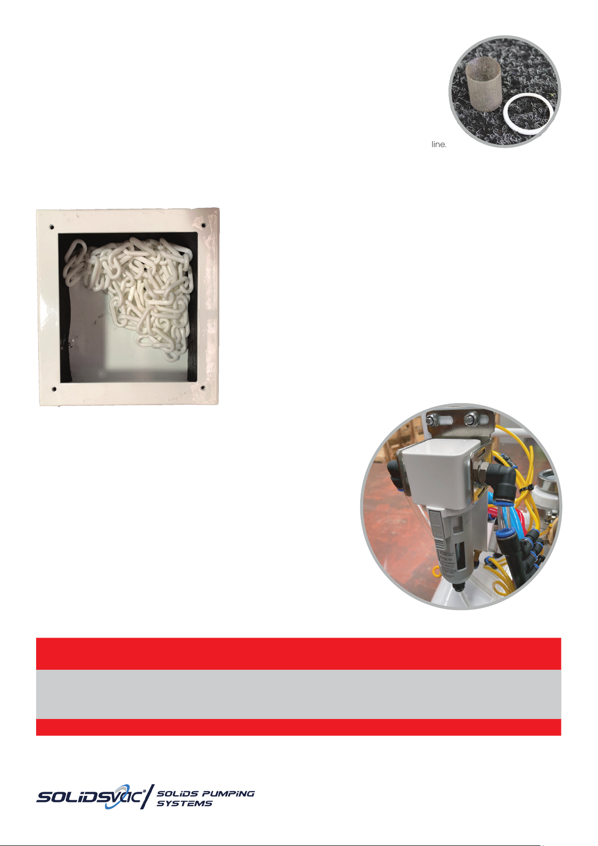
AIR INLET FILTER
Prior to commencing each pumping operation:
- Checkthatallttingsandconnectionareserviceable.
- Adequate compressed air is available.
- A general visual inspection of the unit including the suction and discharge valves
is recommended.
Asmallmetalgauzein-linelterpreventsforeignobjectsenteringtheventurinozzleviatheairsupplyline.
SolidsvacPumpsrecommendperiodicinspectionandcleaningasrequired,replacementltersandsealsareavailablefromyour
Solidsvac suppliers.
EXHAUST BOX
Iftted,SolidsvacPumpsalsorecommendaperiodicvisualinspectionofthe
exhaust box be carried out.
- With the air supply off and isolated, remove the pump cover.
- Visuallychecktheexhaustopeningandifitappearsblocked,eitherush
the box with a hose, alternatively, remove the 4 cap screws in the side
cover.
- Ensure that there is no foreign material inside the box, remove and clean
the chain and insert back into the box.
- Reinstall the cover and recommence operations.
AIR FILTER
TheSolidsvacSV70-SPDKisttedwithanautodrainltertoreduceforeignmedia
entering via the air supply.
Solidsvacrecommendstheairlterisinspectedregularlyandthelteris
changed as required.
SAFETY FIRST
PRIOR TO COMMENCING ANY WORK ON THE UNIT, THE AIR SUPPLY VALVE MUST BE
ISOLATED AND THE CONTROL SYSTEM TESTED DEAD
www.solidsvac.com
page 11
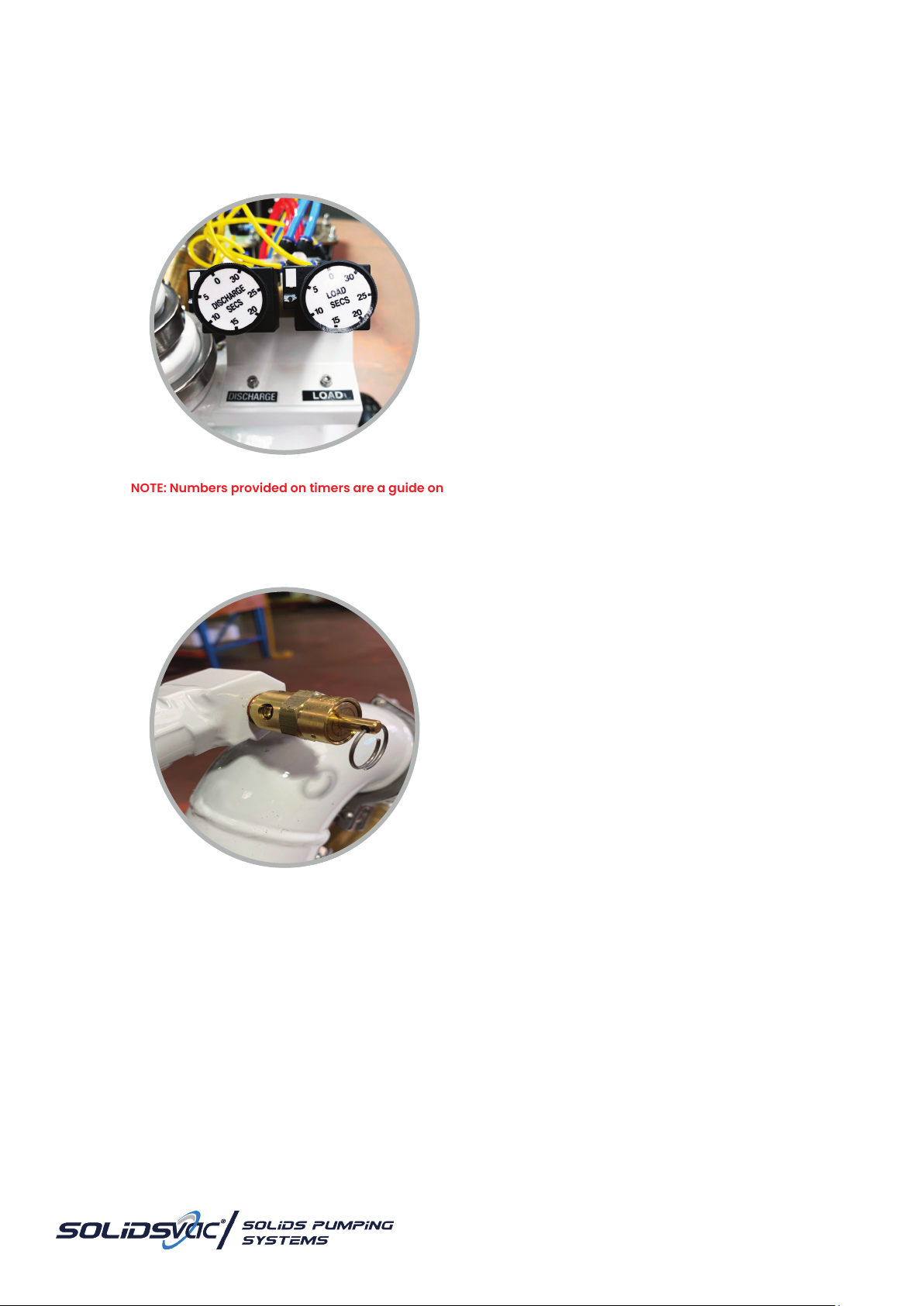
8. ADJUSTING THE LOAD & DISCHARGE CYCLES
Adjusting the LOAD and DISCHARGE cycles may be required depending on the viscosity of the material being transferred and the
distances involved etc. Turning either respective Timer Dial clockwise increases the load or discharge time and turning it anti-clockwise
decreases the load or discharge time.
NOTE: Do NOT turn the knob more than one turn (360’) when adjusting the cycle time.
IMPORTANT NOTE: Numbers provided on timers are a guide only and may not be approximate to actual timer gure indicated.
PRESSURE RELIEF VALVE
The Pressure Relief Valve can be operated by pulling the ring as indicated below:
Adjust timers to dial marking beside each timer.
Only adjust timers when required.
Before starting the pump, adjust timers to
between 4-6 seconds.

telephone +61 456 000 665
email [email protected]
page 12
9. ACCESSORIES
Suction Wand - Attaches to the suction hose allowing the operator to
stand upright and ambient air to be introduced at the material inlet.
Strainer - Available in two sizes and attaches to the suction hose to
prevent the ingestion of oversize particles.
VacHead - An industrial vacuum head with squeegee brush allows the
operator to stand upright, recovering material from hard surfaces i.e. an oil
spill from a road surface.
Note: It is recommended that the suction timing cycle is set to 15 seconds
when using this accessory.
Delivery Carousel - Controlled discharge to either a conveyor or
multiple points/skips etc.
Hoses - A complete range of high quality suction and discharge hoses are
available.
Hoover Head - Helps focus the vacuum and is ideal for recovering
heavier material such as barite, oil sludge, mud or similar from tank bottoms
and various hard surfaces.
Dropbox - Deliveryofmaterialtoaskip,conveyororspecicpoint.
Tool Kit - Contains all you need for basic maintenance on your pump.
Service Kit - Contains all you need for basic maintenance on your pump.

www.solidsvac.com
page 13
OPERATIONAL RISK
ASSESSMENT

telephone +61 456 000 665
email [email protected]
page 14
OBJECTIVE:
Theobjectiveofthehazardidenticationandriskreviewprocessistoensureallhazardsareidentiedandaccuratelyassessedforrisk.
Suitable and effective controls MUST be nominated and implemented to keep workplace safe.
CONTEXT:
The Solidsvac Mobile Solids Pump is designed to be used for the purpose of pumping and transferring heavy slurry/media. The
SolidsvacMobileSolidsPumpwillbeinastationarypositionontheoor.Theoorconditionsneedtobesafeandlevel.
SCOPE:
The Scope of the risk assessment as follows:
1) IdentifyoperationalhazardsassociatedwiththeuseoftheSolidsvacMobileSolidsPump
2) RiskAssesseachoftheidentiedhazards
3) Implementcontrolstominimiseanyhazardstoanacceptablelevel
INVOLVED PERSONS/STAKEHOLDERS:
Risk Facilitator
Solidsvac Management/Tradespeople
ASSUMPTION:
Supplier
Competent, comply with standards and drawings.
End User (Owner/Hirer/User)
The end user has:
- Competent(operatorsaretrained,competent,authorised,etc.)
- Procedures(changemanagement,trafcrules,riskassessed,developed,effectivelyimplemented,etc.)
- Equipmenttforpurpose(rated,designedcompatible,maintained,inspected,monitored,etc.)
- Leadership(communication,directions,monitoring,etc.)
- Environmentalconditionsarecompatibletotheoperationalcapabilitiesoftheequipment(naturalvs.man-made,etc.)
INCLUSIONS:
Only the aspects directly related to Solidsvac Mobile Solids Pump.
EXCLUSIONS:
TransportingandstoringtheSolidsvacMobileSolidsPump(Usersoperationalriskassessment,training,competence);
Assessmentoftheenvironmentalconditionsintheoperationalarea(Usersplanningandlocalriskcontrol)
REFERENCE MATERIAL:
QLD Coal Mining Safety & Health Act 1999
QLD Coal Mining Safety & Health Reg 2001
Recognised Standard 02 Control of Risk Management Practices

www.solidsvac.com
page 15
RISK MATRIX
Step 1: Establish the Consequence (1-5)
Consequences
Injury / Occupational Illness
or Disease
(How to manage Work Health and Safety
Risk – Code of Practice. Safety Work
Australia 10 August 2011). The company
must ensure levels of consequence and
likelihood are relevant to the company’s
Business risk.
Business
Loss/Asset
Damage
Reputation/
Social/
Community
Legal and
Regulatory/
Contract
Environmental
Impact
(e.g. Hydrocarbon spills)
1Insignicant Report only <$5k Complaint/
Single project or
stakeholder
Minor non-
compliance
- internal report
only
Negligible pollution
2 Minor
First Aid Treatment Injury/Illness
Non-prescription medication/
treatment that can be
administered by rst aider.
<$20k Local public
concern
Minor legal non-
compliance -
Contractual issue
Minor pollution/
Nuisance
3 Moderate
Medical Treatment Injury/Illness
Prescription medication/treatment
that can only be administered by a
registered doctor/nurse.
Minor LTI <5 full days work lost
<$50k Regional public
concern/Multiple
stakeholders
Serious breach of
law/Investigation
by authority/
On the spot ne.
Major breach of
contract.
Noticeable pollution
4 Serious
Serious Lost Time Injury/Illness
Loss of 5 or more days work/
admission to hospital/serious
injury under WHSA denition
<$100k National public
concern
Signicant
penalties/
Termination of
contract
Signicant
environmental event
5 Major Fatality
Single or multiple fatalities <$100k International
public concern
Law suits/
Prosecution/
Removal from
suppliers list
Major environmental
event/Material
environmental harm
Step 2: Establish the Likelihood (A-E)
Description Frequency Examples
(How to manage Work Health and Safety Risk – Code of Practice. Safety Work Australia 10 August 2011).
A Certain to occur Expect to occur in most circumstances (>1 event/month)
B Very likely Will probably occur in most circumstances (2 to 1 events/year)
C Possible Might occur occasionally (1 event/1 to 2 years)
D Unlikely Could happen at some time (1 event/2 to 3 years)
E Rare May happen only in exceptional circumstances (>3 to 5 years)
telephone +61 456 000 665
email [email protected]
page 16
RISK MATRIX
Step 3 : The Hierarchy of Risk Control Model
Start at the top and only if you can’t select controls from one section, move to the next one down.
You need to use a combination of control measures to achieve the second level of risk control.
If a particular hazard can’t be removed the risk associated with the hazard can never be eliminated.
1 Elimination Complete removal of the hazard Most effective
2 Substitution Replacing the material of process with a less hazardous one
3 Isolation Separate the hazard from people
4 Engineering Guarding, ventilation, design, re-design etc
5 Administration Providing controls such as training and procedures
6 PPE Use of PPE when other controls are not practical Least effective
7 Post Mitigation after an event (ell Fire extinguisher)
Using the Matrix to Determine Risk Score
Likelihood
Consequences
1 2 3 4 5
A
Certain to occur Low
11 Moderate
16 Moderate
20 High
23 High
25
B
Very likely Low
7Low
12 Moderate
17 High
21 High
24
C
Possible Low
4Low
8Moderate
13 High
18 High
22
D
Unlikely Low
2Low
5Moderate
9Moderate
14 High
19
E
Rare Low
1Low
3Low
6Moderate
10 High
15
ALARP - As low as reasonably practical
Tolerable Take action to manage ALARP Intolerable (without specic senior management approval)

www.solidsvac.com
page 17
Risk Assessment assumes that current
controls are adequate and working.
The Risk Scores have been achieved
using the qualitative risk analysis
matrix from the Solidsvac Risk
Management procedure and is
attached at the end of this document.
OPERATIONAL RISK ASSESSMENT
THIS IS A BASIC R.A
SOLIDSVAC STRONGLY RECOMMEND THAT
A SITE-SPECIFIC R.A IS CONDUCTED.
Reviewed
by Date
REFERENCE ACTIVITY SUB ACTIVITY HAZARD RISK EVENT EXISTING CONTROLS
CURRENT RISK WITH EXISTING CONTROLS RISK TREATMENT
(Accept, Transfer,
Avoid, or Further
RiskReview)
ADDITIONAL RECOMMENDATIONS
STATUS
(Complete,
Incomplete,
Inprogress)
TARGET
RESIDUAL
RISK AFTER
TREATMENT
CONSEQUENCE LIKELIHOOD RISK RATING
1.0 Transport to
work site Travel position Inadequate transport
method
Resulting in personal
injury and damage
to the Solidsvac SV70
Mobile Solids Pump
during transport
Wheels and handle on the Solidsvac SV70
Mobile Solids Pump
Designed well balanced
Mine transport rules
L 8
Placement and loading of the
Solidsvac SV70 Mobile Fluids Pump
to be included in the training and
assessment document in the
Solidsvac SV70 Mobile Solids Pump
Open
1.1 Set up Environment
Solidsvac SV70 Mobile
Solids Pump set up on
uneven ground or pump
is inadequately secured
to rib when on uneven
ground resulting in
unplanned movement
of pump
Resulting in personal
injury and damage
to the Solidsvac SV70
Mobile Solids Pump
during operation
Operation manual and training documents
set up procedure on level ground or
securing pump to the rib using rated
restraining devices when operating on
uneven ground
2 C L8 ALARA Training and assessment in the
Solidsvac SV70 Mobile Solids pump
package
Manual handling Failure of the correct
manual handling
technique
Manual handling training at Induction team
lifts where required
Most set up and removal tasks conducted
fromoorlevelandreasonableheight
2 C L 8 ALARA Training and assessment in the
Solidsvac SV70 Mobile Solids pump
package
1.2 Operation
Nip/crush points and
“Line of Fire” issues from
mobile equipment, low
roof height issues during
set up and removal
resulting in crush injuries
Resulting in personal
injury
Operation manual and training documents
setup, removal procedures
Operation manual and training documents
identify the need to drain pump before
disconnecting. Mine transport rules Line of
sight before any movements
No machine movements without positive
communications
Hi-viz clothing
3 C M 13 ALARA Training and assessment in the
Solidsvac SV70 Mobile Solids pump
package
High pressure
compressed air
Failure of the
compressed air
system resulting in:
Personal injury from
being exposed to
compressed air due
to hose failure and/or
damage
Rated pressure hoses
Mine Site Induction and Training
Competencies 3 C M 13 ALARA
Work on or around a
moving belt
Interaction with
conveyor resulting in
personal injury
Mine Site Induction and Training
Competencies 2 C L 8 ALARA
Discharged material
(at100psi)contacts
operators
Resulting in personal
injury
Operation manual and training documents
the set up procedure incorporates
barricading discharge area with caution
tape
2 C L 8 ALARA
Pinch points on Solidsvac
SV70 Mobile Solids pump
during operation
Resulting in personal
injury Fitforpurposecoversttedtopumpduring
operation, MUST be in place 2 C L 8 ALARA
Blocked discharge hose
resulting in exposure
to stored energy while
unblocking hose
Resulting in personal
injury
Operation manual and training documents
unblocking procedure
Pressure relief valve at the pump relieves
discharge pump pressure
2 C L 8 ALARA
Blocked suction hose
resulting in process delay
Resulting in personal
injury and/or process
delay
Operation manual and training documents
unblocking procedure
Isolation training and procedures
Low pressure i.e. 10psi
Strainerornozzlettedtosuctionhose
2 C L 8 ALARA
1.3 Maintenance Incorrect maintenance
resulting in equipment
failure
Resulting in personal
injury and/or process
delay
Tested to Australian Standards
OEM Maintenance scheme 2 C L 8 ALARA Maintenance to be carried out as
per OEM Suppliers SV70
Operation/Maintenance Manual
telephone +61 456 000 665
email [email protected]
page 18
RISK REGISTER ACTION PLAN
No ITEM/ISSUE AGREED ACTION WHO WHEN COMP DATE REVIEW/AUDIT
DATE
Operation Storage Communicate to end user to
develop work procedures for
storage of Solidsvac SV70 Mobile
Fluids Pump
Solidsvac Delivery
Travel position Communicate to end user to
develop work procedures for
travelling
Solidsvac Delivery
Use of Solidsvac
SV70 Mobile
Fluids Pump
Supplier to develop work
procedures for operating the
Solidsvac SV70 Mobile Solids Pump
Solidsvac Delivery
Maintenance Daily Supplier to develop daily
and/or pre-use visual inspections
procedures for using and
operating the Solidsvac SV70
Mobile Solids Pump
Solidsvac Delivery
Weekly Supplier to develop weekly
visual, operational, maintenance
inspections for using and
operating the Solidsvac SV70
Mobile Solids Pump
Solidsvac Delivery

www.solidsvac.com
page 19
PUMP PREVENTATIVE
MAINTENANCE PROGRAM
The following is the work to be performed to a SV70-SPDK Pump during Preventative Maintenance Check.
All items, except annual checks (Tradesman), are to be carried out by a Competent Operator.
- Lock and tag out equipment
- Record equipment data
- Checkallmountingandangeboltsaresecureandtight
- Check vessel support frame and wheels for soundness
- Visual inspection of pump for any damage
- Check for knife gate seal leaks
- Checkconditionofangegaskets
- Check knife gate packing for excessive leakage and adjust and/or replace
- Make sure all timers are operational
- Check operation of Pressure Relief Valve
- Checkin-linegauzelter
- Inspectconditionofairlinesandttings
- Checkoperationofswingcheckvalve(iftted)
- Check condition of venturi nozzle
- Test the operation of the SV70-SPDK pump prior to returning to service
- Makenoteontheeldreportofanyndingsthatmayrequireadditionalwork

telephone +61 456 000 665
email [email protected]
page 20
PUMP MAINTENANCE CHECKLIST
DESCRIPTION COMMENT
MAINTENANCE FREQUENCY
DAILY WEEKLY MONTHLY ANNUALLY
Pump use and
timing Check operation of pump prior to use. X
Overall visual
inspection
Complete overall visual inspection to be sure all
equipment is operating and safety systems are in
place. X
Check knife gate
seals Assure that all seals are in good condition and not
worn, split or damaged. X
Check knife gate
packing Check packing for wear and leakage and repack as
necessary. X
Check airlines and
ttings Inspectairlinesforanydeterioration,checkttingsfor
cracks and leaking. X
Check bolts Checkandsecureallangebolts. X
Check in-line gauze
lter Checkin-linelterforcleanlinessandobstructions.
Clean as necessary. X
Check venturi
nozzle and PRV Check the condition of the venturi nozzle. Check
operation of the PRV. X
Pressure Vessel
Inspection Inspect the vessel for wear, cracks and/or damage. X
Full Service and PRV Conduct a full service on the pump and replace the
PRV. X
Table of contents
Other SOLIDSVAC Water Pump manuals


Popular Water Pump manuals by other brands

SAMES KREMLIN
SAMES KREMLIN REXSON 4B6000 user manual

Pentair
Pentair JUNG PUMPEN SKS 800 Series instruction manual

ewuaqua
ewuaqua iMizar OPP 9-8 Installation and operation manual

Pentair
Pentair MYERS MSP50A owner's manual

Whale
Whale Gulper 220 user manual

Ruby
Ruby 025 FDA Installation, operation and maintenance


Grundfos
Grundfos CR Service instructions

BSC
BSC GVD8-Single phase instruction manual

Textron
Textron Greenline H4665A instruction manual

Renkforce
Renkforce 1526585 operating instructions

Pentair
Pentair MYERS SP33 Series Installation, Operation & Parts Manual

TorcUP
TorcUP EP500 Owner's operation and maintenance manual