Sollatek AVS30 User manual

The Sollatek AVS30 Appliance Guard
Models covered:
AVS30
Important: This manual contains
important safety instructions.
Keep this manual handy for reference.
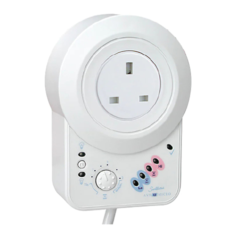
The AVS30 micro is a single phase Automatic
Voltage Switcher rated at 30 Amps. The AVS30
will switch off the equipment connected to it if
the mains power goes outside pre-set acceptable
limits, and will reconnect automatically when the
mains power returns to normal. Reconnection
takes place after a delay, to ensure stability of the
mains. The new version of the AVS30 has a built-in
microprocessor that adds advanced features.
Loss of neutral is a serious common condition.
In this event, the single phase voltage will then rise
to the three phase level subjecting your equipment to >400V instead of 230V.
This can be catastrophic for your appliance. To protect against this, the AVS30 can
protect against temporary over voltage of 400V (TOV400).
By adding microprocessor control to the AVS30, you can enjoy advanced functions
which include:
• Variable time delay
• Variable Low voltage disconnect level
• Variable High voltage disconnect level
• Variable Blind time. Response time to under voltage disconnect
• Intelligent time delay
All these new features can be set at installation time.
• The AVS30 has a reset button on the front panel. This button will eliminate
the delay time.
• 5 LEDs to indicate the state of the mains supply.
LED Colour Indicating Load Status
Red High incoming voltage OFF
Yellow AVS30 is in wait state after a high voltage transition OFF
Green Mains normal ON
Yellow AVS30 is in wait state after a low voltage transition OFF
Red Low incoming voltage OFF
USER INSTRUCTIONS
Five LEDs accurately display the
status of the AVS30 in the following
symmetrical traffic light design:
AVS30 label
Stock number: 74545904
Dec 08
74107030 AVS30 Instruction Manual English July 2020 115x193mm V5.indd 174107030 AVS30 Instruction Manual English July 2020 115x193mm V5.indd 1 14/07/2020 11:2814/07/2020 11:28

Model AVS30 micro 110V 230V
Current (Amps) 30 30
Nominal voltage(V) 110 230
Wait time (mins) 10 secs to 10mins+manual 10 secs to 10mins+manual
Under-voltage disconnect(V) 75-110 150-230
Over-voltage disconnect(V) 110-150+off 230-300+off
Hysteresis(V) 3-5 3-5
Socket type direct via brass screw terminal direct via brass screw terminal
Fused plug N/A N/A
RFI protection No No
Transient suppression Yes >6.5kA Yes >6.5kA
Spike protection(J) 80 160
SPECIFICATIONS
CONNECTION:
CAUTION: IF THE AVS30 IS ALREADY WIRED, MAKE SURE IT IS DISCONNECTED FROM
THE MAINS BEFORE YOU DO ANY OF THE FOLLOWING;
1. Remove the bottom cover to obtain access to connection terminals. To remove
bottom cover remove the two white caps and then undo the two screws.
2. Remove the two cable glands and then re-insert them so that the cable gland
is external.
3. Insert cable from the mains supply through the cable glands of the AVS30 and
connect to the connector terminals. (Refer to connection terminals layout diagram
on next page).
4. Insert cable to appliance through the cord grip bush and connect to the connector
terminals.
5.
Tighten the cord grip bushes and return the front cover and two screws and screw caps.
PLEASE ENSURE NOT TO TIGHTEN CONNECTION TERMINALS EXCESSIVELY.
NOTES:
• In the upper compartment of the AVS30, you will find a fuse (see diagram overleaf).
The fuse is not for the load. It is a spike protection fuse. Replace if it gets damaged.
(0.5A Anti Surge). To gain access to the upper compartment, ENSURE THAT THE
AVS30 IS NOT CONNECTED TO THE MAINS. Remove the screws from the back.
• The AVS30 must be mounted securely on a wall. Place it over one screw at the top
and then use the two mounting holes in the terminal compartment.
• The supply to the AVS30 must be fitted with a 30A HBC fuse or less.
74107030 AVS30 Instruction Manual English July 2020 115x193mm V5.indd 274107030 AVS30 Instruction Manual English July 2020 115x193mm V5.indd 2 14/07/2020 11:2814/07/2020 11:28

AVS30 INPUT
L (Live) to L
N (Neutral) to N
E (Earth) to E
AVS30 OUTPUT
L (Live) to L out
N (Neutral) to N out
E (Earth) to E out if used
AVS30 CONNECTION TERMINALS LAYOUT
OPERATION
1. Make sure that your load does not exceed the rating of the AVS30 which is 30Amps.
2. The limits of the AVS30 as a standard are set for a window of 190-260 volts.
3. The AVS30 has to be wired to the mains supply and to the equipment it is supplying.
Please refer to the wiring diagram below.
4. On first switching on, there will be no output for the wait time of approximately three
minutes while the AVS30 monitors the mains.
a) To by-pass the wait time, press the re-set button on the front panel of the AVS30.
b) If a different wait time is required, then change the settings on potentiometer
marked WAIT. Settings are available in increments up to 10 minutes. You can also
set the WAIT dial to MAN. While on MAN the AVS30 will not reconnect the mains
unless the Reset button is pressed. For that period the yellow LED indicates that
the mains are within acceptable limits, after which the green LED goes on and the
load is connected.
5. A different blind time can be set if a different under voltage disconnect limit is
required. Under voltage blind time means the AVS30 ignores any undervoltage
conditions during this time. The AVS30 will not switch off unless the under voltage
last longer than the blind time.
6. It is recommended that the AVS30 is kept switched on, and the appliance switched on
and off to prevent activating the time delay every time the appliance is switched on.
74107030 AVS30 Instruction Manual English July 2020 115x193mm V5.indd 374107030 AVS30 Instruction Manual English July 2020 115x193mm V5.indd 3 14/07/2020 11:2814/07/2020 11:28

Liability of the Company
(a) The Company shall not be liable, either in contract or in tort for any loss, injury or
damage of whatsoever nature or to whomsoever or by whatsoever cause arising
directly or indirectly from any defect in the Goods (whether latent or apparent) or as
a result of the use of the Goods (save and except any liability for death of or injury to
any person resulting directly from the negligence of the Company) and the Customer
shall fully indemnify the Company against all claims and demands made upon the
Company by reason of any such loss or injury or damage.
(b) Without prejudice to the provisions of the immediately preceding sub clause the
Company shall not in any event be liable for consequential or indirect loss or damage
howsoever arising under the Contract or in relation to the Goods.
(c) The Customer hereby acknowledges that the restrictions in this clause are fair and
reasonable in the circumstances.
Warranty
Unless otherwise agreed with the Company or where the Company has notified the
Customer of special terms in respect of specified categories of goods the Company
agrees at its option either to refund the cost of or repair or replace goods proved to the
Company’s reasonable satisfaction to have failed under proper storage and use within
24 months of delivery by reason of defects due to faulty design (other than any design
made, furnished or specified by the Customer) materials or workmanship provided that:
(a) The Customer shall have followed any instruction issued by the Company in relation to
the goods and their storage;
(b) In the case of defects which would have been apparent to the Customer on reasonable
examination of the goods on delivery, ‘the’ Customer shall notify the Company of the
defects within 14 days of delivery;
(c) In the case of any other defects the Customer shall notify the Company of the defects
in writing within 7 working days of the date when the defect becomes apparent;
(d) Where in discharge of its obligation under this clause the Company agrees that the
Customer may undertake any repair work on its behalf the cost of such work shall be
agreed in writing between the Customer and the Company before the commencement
of such work.
Return of Goods
(a) Goods supplied in accordance with the Customer’s orders cannot be accepted for
return without the prior written consent of the Company and in accordance with the
Company’s returns procedure.
(b)The Company reserves the right to levy a handling, administration or other charge of
such amount as it, in its absolute discretion, decides and may deduct this from any
credit allowed unless the reason for any return by the Customer is due to any fault or
breach of these Conditions on the part of the Company.
(c) Returned Goods must be sent carriage paid at the Customer’s risk to the Company’s
trading premises or to such other address as the Company may direct.
(d) The Company will not allow credit in respect of returned goods not in fully
re-saleable condition.
ISO9001: 2015 accredited
company
All weights and dimensions are
approximate. Specifications are
subject to change without prior
notice. ©Sollatek (UK) Limited
2019. All Rights Reserved.
SOLLATEK and the SOLLATEK
device are the trade marks of the
Sollatek group of companies.
MJA July 2020
AVS30 Micro Controlled Instruction Manual
A/I: 10910577
S/C: 74107030
SOLLATEK UK LTD.
Tel: +44 (1753) 214 500
www.sollatek.com
Sollatek House
Waterside Drive
Langley, Slough
SL3 6EZ UK
74107030 AVS30 Instruction Manual English July 2020 115x193mm V5.indd 474107030 AVS30 Instruction Manual English July 2020 115x193mm V5.indd 4 14/07/2020 11:2814/07/2020 11:28
Table of contents
Other Sollatek Switch manuals
Popular Switch manuals by other brands
SeaLevel
SeaLevel SeaI/O-270U user manual
SMC Networks
SMC Networks SMCGS10P-Smart Management guide
Emcotec
Emcotec RC Electronic SPS-RCS quick start guide
Briggs & Stratton
Briggs & Stratton 695061 Series Operating & installation instructions
Panasonic
Panasonic Switch-S24GPWR installation guide
THOMSON
THOMSON TTN-BAS-0808CP installation manual


