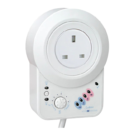
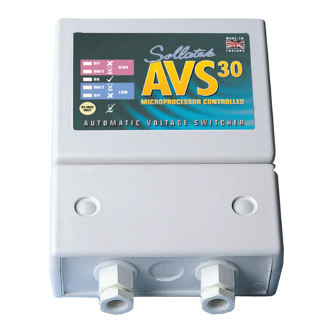
Sollatek Voltshield AVS3P-0 User manual

LIABILITY OF THE COMPANY
a) The company shall not be liable, either in contract or in tort for any loss, injury or
damage of whatsoever nature or to whomsoever or by whatsoever cause arising
directly or indirectly from any defect in the Goods (whether latent or apparent) or
as a result of the use of the Goods (save and except any liability for death of or
injury to any person resulting directly from the negligence of the company) and the
customer shall fully indemnify the company against all claims and demands made
upon the company by reason of any such loss or injury or damage.
b) Without prejudice to the provisions of the immediately preceding sub clause
the company shall not in any event be liable for consequential or indirect loss or
damage howsoever arising under the contract or in relation to the Goods.
c) The customer hereby acknowledges that the restrictions in this clause are fair and
reasonable in the circumstances.
WARRANTY
Unless otherwise agreed with the company or where the company has notied the
customer of special terms in respect of specied categories of goods the company
agrees at its option either to refund the cost of or repair or replace goods proved to
the company’s reasonable satisfaction to have failed under proper storage and use
within 24 months of delivery by reason of defects due to faulty design (other than
any design made, furnished or specied by the customer) materials or workmanship
provided that:
a) The customer shall have followed any instruction issued by the company in relation
to the goods and their storage.
b) In the case of defects which would have been apparent to the customer on
reasonable examination of the goods on delivery, ‘the’ customer shall notify the
company of the defects within 14 days of delivery.
c) In the case of any other defects the customer shall notify the company of the
defects in writing within 7 working days of the date when the defect becomes
apparent.
d) Where in discharge of its obligation under this clause the company agrees that
the customer may undertake any repair work on its behalf the cost of such work
shall be agreed in writing between the customer and the company before the
commencement of such work.
RETURN OF GOODS
a) Goods supplied in accordance with the customer’s orders cannot be accepted for
return without the prior written consent of the company and in accordance with the
company’s returns procedure.
b) The company reserves the right to levy a handling, administration or other charge
of such amount as it, in its absolute discretion, decides and may deduct this from
any credit allowed unless the reason for any return by the customer is due to any
fault or breach of these conditions on the part of the company.
c) Returned goods must be sent carriage paid at the customer’s risk to the company’s
trading premises or to such other address as the company may direct.
d) The company will not allow credit in respect of returned goods not in fully re-
saleable condition.
SAFETY
All equipment designed and manufactured by Sollatek (UK) Ltd
complies with the latest safety codes of practice. You should still
follow all safety instructions and use caution when installing and
operating electrical equipment.
To avoid the risk of a shock, DO NOT expose this equipment
to rain, moisture, or liquid spillage. Before attempting to use it,
ensure that the contactor solenoid does not exceed 16 amps. The
equipment load must not exceed the contactor rating.
START-UP
WAIT When the AVS3P is powered up, it will enter Wait Mode and your
equipment will remain OFF.
ON After the wait time has elapsed, the AVS3P connects the supply to turn
your equipment ON.
Start-up Error
OFF
WAIT
OFF
All three phases must be sensed in order to operate. If on power up
one or more phases cannot be sensed, the AVS3P will remain in the
off position. Equipment will remain OFF.
STANDARD OPERATION
OFF High Voltage. Equipment OFF
WAIT Good Voltage, recovered from high voltage. AVS3P in Wait Mode,
equipment OFF
ON Good Voltage. Equipment ON
WAIT Good Voltage, recovered from low voltage. AVS3P in Wait Mode,
equipment OFF
OFF Low Voltage. Equipment OFF
The AVS3P can also be set to protect against bad frequency (goes outside the
operating range), phase imbalance (voltage deviation) and/or phase rotation (phases
are swapped post-commissioning).
WAIT MODE
Wait Mode provides voltage monitoring and protection against power-back surges
and frequent power-ups by ensuring the mains power has fully stabilised before
automatically reconnecting it to your equipment after the set wait time has elapsed.
The AVS3P will automatically adjust the wait time depending on the disconnection
period to make the total OFF time equal to the set Wait Time. i.e. If Wait Time is 3
minutes and the disconnection is 2 minutes, then the wait time added is just 1 minute.
TIMESAVE™
If the AVS3P has been turned OFF for more than the set wait time, The AVS3P will
reconnect the supply to your loads in 10 seconds.
MJA 07/09/2023 AVS3P-0 User Manual Sept 2023 v1
A/I: 10910892 S/C: 74108404
RISK OF
ELECTRIC SHOCK
AVS3P-0
VoltshieldTM
The Switcher Range
VoltsafeTM
The Suppressor Range
VoltrightTM
The Stabiliser and Regulator Range
VoltsureTM
The UPS Range
AVS3P-0
APPLIANCE GUARD
3-PHASE AUTOMATIC VOLTAGE SWITCHER
USER MANUAL

ELECTRICAL CONNECTIONS
Access Terminal Compartment
Wall Mounting Wiring
N L E
N = Neutral
L = Live
E = Earth
AVS3P-0
From Mains
To Equipment
A1
A2
N
CC
N
O
A1
N
CC
N
O
R
N
CC
N
O
S
T
N
T1
L1 L2
T2 T3
L3
N
N
Contactor
1 2 3 4
1 2 3 4
OFF OFF
ON ON
R
N
CC
N
OA1
R
N
CC
N
O
S
T
N
A2 A1
LINK TO POWER
SOLENOID
SENSE WIRES FROM
LOAD CONTACTOR (INPUT SIDE)
CONTACTOR
SOLENOID
OK
ALARMED
1) Connect sensing cables from L1 to
R, L2 to S and L3 to T. Connect the
neutral to A2 and N.
The output from the AVS3P is a
changeover relay with volt-free contacts.
• Good Voltage: C connects to NO
• Bad Voltage/wait mode: C connects
to NC
2a) Contactor
• Connect NO to A1
• Connect C to L1
2b) Control Circuit
• Connect NO to A1
• Connect C to the external
controller/control circuit
2c) Remote Monitoring
• Connect NC to the stop control
• Connect NO to the start control
• Connect C to the 24 Vdc supply
REPAIR/MAINTENANCE
The internal surge protection fuse may
blow during a severe surge.
Only a qualied person should carry out
repairs. Ensure power is isolated.
1) Remove the terminal cover.
Access Terminal Compartment
Wall Mounting Wiring
N L E
N = Neutral
L = Live
E = Earth
AVS3P-0
From Mains
To Equipment
A1
A2
N
CC
N
O
A1
N
CC
N
O
R
N
CC
N
O
S
T
N
T1
L1 L2
T2 T3
L3
N
N
Contactor
1 2 3 4
1 2 3 4
OFF OFF
ON ON
R
N
CC
N
OA1
R
N
CC
N
O
S
T
N
A2 A1
LINK TO POWER
SOLENOID
SENSE WIRES FROM
LOAD CONTACTOR (INPUT SIDE)
CONTACTOR
SOLENOID
OK
ALARMED
2) Ensure to replace the fuse with a fuse
of the same type and rating: 5.0A
HBC anti-surge fuse (20x5mm).
ENABLE ADDITIONAL PROTECTION
Phase rotation, voltage phase imbalance
& frequency error, can be enabled via the
switches inside the top compartment.
Ensure power is isolated before
removing the top cover.
Access Terminal Compartment
Wall Mounting Wiring
N L E
N = Neutral
L = Live
E = Earth
AVS3P-0
From Mains
To Equipment
A1
A2
N
CC
N
O
A1
N
CC
N
O
R
N
CC
N
O
S
T
N
T1
L1 L2
T2 T3
L3
N
N
Contactor
1 2 3 4
1 2 3 4
OFF OFF
ON ON
R
N
CC
N
OA1
R
N
CC
N
O
S
T
N
A2 A1
LINK TO POWER
SOLENOID
SENSE WIRES FROM
LOAD CONTACTOR (INPUT SIDE)
CONTACTOR
SOLENOID
OK
ALARMED
1) Remove the 4 screws from the rear of
the unit and then remove the cover.
Access Terminal Compartment
Wall Mounting Wiring
N L E
N = Neutral
L = Live
E = Earth
AVS3P-0
From Mains
To Equipment
A1
A2
N
CC
N
O
A1
N
CC
N
O
R
N
CC
N
O
S
T
N
T1
L1 L2
T2 T3
L3
N
N
Contactor
1 2 3 4
1 2 3 4
OFF OFF
ON ON
R
N
CC
N
OA1
R
N
CC
N
O
S
T
N
A2 A1
LINK TO POWER
SOLENOID
SENSE WIRES FROM
LOAD CONTACTOR (INPUT SIDE)
CONTACTOR
SOLENOID
OK
ALARMED
2) Turn ON the required function(s) by
sliding the switch from right to left.
3) Replace and secure the top cover
before powering ON.
SETTING CHANGE
Dial Range Default Description
Delay
Time
OFF, 30
sec to 10
min
3 min The duration that the AVS3P will monitor the voltage
before connecting it to your equipment after start-up or a
disconnection period caused by high or low voltage.
If set to OFF, the power will be connected to your
equipment after a 10 second sensing delay.
High
Voltage
230 V to
300 V, OFF
260 V The maximum voltage that the AVS3P will still power your
equipment. The AVS3P will disconnect the equipment
from the supply when the voltage exceeds this set value.
If set to OFF, the AVS3P will continue to supply the
equipment regardless of the voltage value.
Low
Voltage
OFF, 160 V
to 230 V
200 V The minimum voltage that the AVS3P will still power your
equipment. When the voltage falls below this set value,
the AVS3P will disconnect the equipment from the supply.
If set to OFF, the AVS3P will continue to supply the
equipment down to 150V (minimum working voltage),
below this, the AVS3P will disconnect the supply.
Note: Always match the set AVS3P limits to the equipment requirements.
SPECIFICATION
Nominal Voltage 230 V / 400 V
Maximum Supply Voltage 320 V
Current 16 A Max. (drives contactor solenoid)
Max Consumption 35 VA
Voltage Disconnect Off, 160 to 300 V (user settable)
Hysteresis (reconnection voltage) 3 V from set limits
Low Voltage Blind Time 1 s
High Voltage Blind Time 0.5 s
Wait Time OFF, 30 s to 10 min
Spike Protection 160 J
Mains Spike Discharge 6.5 kA
Spike Response Time <10 ns
Temporary Over Voltage (TOV) 415 V
Extra Voltage Protection Frequency, Phase Imbalance & Phase Rotation
Frequency 47 to 52 Hz & 57 to 62 Hz
Voltage Phase Imbalance Detection 4.8%
Connector Screw Terminals
Unit Dimensions 184 x 134 x 53 mm (without cable glands)
Unit Weight 500 g
TERMINAL COMPARTMENT
Within the Terminal compartment, there
are terminals for electrical connections,
unit mounting holes, and setting dials.
Isolate the power to the AVS3P before
removing the terminal cover.
Access Terminal Compartment
Wall Mounting Wiring
N L E
N = Neutral
L = Live
E = Earth
AVS3P-0
From Mains
To Equipment
A1
A2
N
CC
N
O
A1
N
CC
N
O
R
N
CC
N
O
S
T
N
T1
L1 L2
T2 T3
L3
N
N
Contactor
1 2 3 4
1 2 3 4
OFF OFF
ON ON
R
N
CC
N
OA1
R
N
CC
N
O
S
T
N
A2 A1
LINK TO POWER
SOLENOID
SENSE WIRES FROM
LOAD CONTACTOR (INPUT SIDE)
CONTACTOR
SOLENOID
OK
ALARMED
1) Remove the screw hole covers.
2) Loosen the two xing screws and
remove them from the hole.
Access Terminal Compartment
Wall Mounting Wiring
N L E
N = Neutral
L = Live
E = Earth
AVS3P-0
From Mains
To Equipment
A1
A2
N
CC
N
O
A1
N
CC
N
O
R
N
CC
N
O
S
T
N
T1
L1 L2
T2 T3
L3
N
N
Contactor
1 2 3 4
1 2 3 4
OFF OFF
ON ON
R
N
CC
N
OA1
R
N
CC
N
O
S
T
N
A2 A1
LINK TO POWER
SOLENOID
SENSE WIRES FROM
LOAD CONTACTOR (INPUT SIDE)
CONTACTOR
SOLENOID
OK
ALARMED
3) Lift the terminal cover to remove it.
Access Terminal Compartment
Wall Mounting Wiring
N L E
N = Neutral
L = Live
E = Earth
AVS3P-0
From Mains
To Equipment
A1
A2
N
CC
N
O
A1
N
CC
N
O
R
N
CC
N
O
S
T
N
T1
L1 L2
T2 T3
L3
N
N
Contactor
1 2 3 4
1 2 3 4
OFF OFF
ON ON
R
N
CC
N
OA1
R
N
CC
N
O
S
T
N
A2 A1
LINK TO POWER
SOLENOID
SENSE WIRES FROM
LOAD CONTACTOR (INPUT SIDE)
CONTACTOR
SOLENOID
OK
ALARMED
4) Replace and secure the terminal
cover before powering ON.
MOUNTING
1) Mark and drill the top mounting hole
Access Terminal Compartment
Wall Mounting Wiring
N L E
N = Neutral
L = Live
E = Earth
AVS3P-0
From Mains
To Equipment
A1
A2
N
CC
N
O
A1
N
CC
N
O
R
N
CC
N
O
S
T
N
T1
L1 L2
T2 T3
L3
N
N
Contactor
1 2 3 4
1 2 3 4
OFF OFF
ON ON
R
N
CC
N
OA1
R
N
CC
N
O
S
T
N
A2 A1
LINK TO POWER
SOLENOID
SENSE WIRES FROM
LOAD CONTACTOR (INPUT SIDE)
CONTACTOR
SOLENOID
OK
ALARMED
2) Use an appropriate wall xing to
fasten a screw into the hole, leaving
the screw extruding about 10 mm.
3) Hang the AVS on the protruding
screw using the notch on the back of
the AVS3P.
Access Terminal Compartment
Wall Mounting Wiring
N L E
N = Neutral
L = Live
E = Earth
AVS3P-0
From Mains
To Equipment
A1
A2
N
CC
N
O
A1
N
CC
N
O
R
N
CC
N
O
S
T
N
T1
L1 L2
T2 T3
L3
N
N
Contactor
1 2 3 4
1 2 3 4
OFF OFF
ON ON
R
N
CC
N
OA1
R
N
CC
N
O
S
T
N
A2 A1
LINK TO POWER
SOLENOID
SENSE WIRES FROM
LOAD CONTACTOR (INPUT SIDE)
CONTACTOR
SOLENOID
OK
ALARMED
4) Ensure the unit is level before
marking and drilling the two bottom
mounting holes.
5) If wall xings are required, remove
the AVS3P from the wall and insert
xings into the wall. Replace the
AVS3P on the top screw.
6) Tighten 2 screws into the bottom
mounting holes to secure the AVS3P
to the wall.
AVS3P WIRING
Access Terminal Compartment
Wall Mounting Wiring
N L E
N = Neutral
L = Live
E = Earth
AVS3P-0
From Mains
To Equipment
A1
A2
N
CC
N
O
A1
N
CC
N
O
R
N
CC
N
O
S
T
N
T1
L1 L2
T2 T3
L3
N
N
Contactor
1 2 3 4
1 2 3 4
OFF OFF
ON ON
R
N
CC
N
OA1
R
N
CC
N
O
S
T
N
A2 A1
LINK TO POWER
SOLENOID
SENSE WIRES FROM
LOAD CONTACTOR (INPUT SIDE)
CONTACTOR
SOLENOID
OK
ALARMED
1) Insert the wires through the gland
nut and the glands.
2) Connect the corresponding wires to
the AVS3P terminals.
3) Tighten the cable gland nuts and
secure the terminal cover in place.
1Phase Rotation Error
2Phase Imbalance Error
3Frequency Error
4Not Connected
Access Terminal Compartment
Wall Mounting Wiring
N L E
N = Neutral
L = Live
E = Earth
AVS3P-0
From Mains
To Equipment
A1
A2
N
CC
N
O
A1
N
CC
N
O
R
N
CC
N
O
S
T
N
T1
L1 L2
T2 T3
L3
N
N
Contactor
1 2 3 4
1 2 3 4
OFF OFF
ON ON
R
N
CC
N
OA1
R
N
CC
N
O
S
T
N
A2 A1
LINK TO POWER
SOLENOID
SENSE WIRES FROM
LOAD CONTACTOR (INPUT SIDE)
CONTACTOR
SOLENOID
OK
ALARMED
Notes:
•
WAIT LED indicates alarm level clearance
(10s or user-selected DELAY timeout).
•
If Delay is OFF, default 10-second delay is
automatically activated.
•
If LVD is OFF, only default 150V fast OFF is
active.
•
If HVD is OFF, no high-level voltage protection.
Turn the dial with a small
screwdriver or your thumb to
make necessary adjustments.
Access Terminal Compartment
Wall Mounting Wiring
N L E
N = Neutral
L = Live
E = Earth
AVS3P-0
From Mains
To Equipment
A1
A2
N
CC
N
O
A1
N
CC
N
O
R
N
CC
N
O
S
T
N
T1
L1 L2
T2 T3
L3
N
N
Contactor
1 2 3 4
1 2 3 4
OFF OFF
ON ON
R
N
CC
N
OA1
R
N
CC
N
O
S
T
N
A2 A1
LINK TO POWER
SOLENOID
SENSE WIRES FROM
LOAD CONTACTOR (INPUT SIDE)
CONTACTOR
SOLENOID
OK
ALARMED
Optional Settings Standard Functions
(Dip switches 1 to 3, one at a time)
(Thumbwheel settings)
LED 4 3 2 1 LVD HVD DELAY
High. OFF
High. WAIT
ON
Low. WAIT
Low. OFF
No LED
indication
other than
WAIT.
Not Connected
Detection
Access Terminal Compartment
Wall Mounting Wiring
N L E
N = Neutral
L = Live
E = Earth
AVS3P-0
From Mains
To Equipment
A1
A2
N
CC
N
O
A1
N
CC
N
O
R
N
CC
N
O
S
T
N
T1
L1 L2
T2 T3
L3
N
N
Contactor
1 2 3 4
1 2 3 4
OFF OFF
ON ON
R
N
CC
N
OA1
R
N
CC
N
O
S
T
N
A2 A1
LINK TO POWER
SOLENOID
SENSE WIRES FROM
LOAD CONTACTOR (INPUT SIDE)
CONTACTOR
SOLENOID
OK
ALARMED
Other Sollatek Switch manuals
Popular Switch manuals by other brands

Enovation Controls
Enovation Controls Murphy DF Series Installation and operation manual
Ecco
Ecco SW15 Installation and operation instructions
AMX
AMX Enova DVX-2110HD-SP quick start guide
EMP-Centauri
EMP-Centauri T1/1+1ENP8dB-1 instruction manual
Matrix Switch Corporation
Matrix Switch Corporation MSC-XD1608L product manual
EtherWAN
EtherWAN EX24000 user guide
