Solpal L User manual

www.solpal.us
Installation and operating manual
Instrucciones de instalación y montaje
EN
ES

2
Contents Solpal L
Índice Solpal L
• Safety instruction......................................................... 3
Instrucciones de seguridad ....................................................... 4
• Recurring note.............................................................. 5
Nota recorrente..............................................................................5
• Overview of Materials.................................................. 6
Lista de materiales........................................................................6
• Transport note.............................................................. 7
Indicações de transporte............................................................7
• Explanation of symbols ............................................... 8
Explicación de los símbolos .......................................................8
• Solpal L.......................................................................... 9
• Specications for water quality ............................... 10
Datos sobre la calidad del agua............................................. 10
• Hydraulic connection ............................................... 11
Conexión hidráulica ................................................................... 11
• Flat-Roof installation ................................................ 16
Montaje en tejado plano.......................................................... 16
• On-Roof installation................................................... 21
Montaje sobre tejado ..................................................................21
• English
Installation instructions ..............................................................24
Warranty...........................................................................................25
Operating instructions................................................................26
• Español
Indicaciones para el montaje....................................................28
Garantía ............................................................................................29
Notas sobre el funcionamiento................................................30
• Appendix .................................................................... 32
Apéndice..........................................................................................40
ES
EN
691100203.1 / 2018-01

3
Safety instruction
USER MUST BE IN COMPLIANCE WITH ALL APPLICABLE
FEDERAL, STATE, AND MUNICIPAL BUILDING AND FIRE
SAFETY LAWS, CODES, AND REGULATIONS.
CHECK THE UNIT AND THE ACCESSORIES FOR ANY VISI-
BLE DEFECTS, CRACKS, OR OTHER DAMAGES AFTER UN-
PACKING AND BEFORE FIRST USE. IF YOU SEE ANY DAM-
AGE, DO NOT USE THE PRODUCT. CONTACT CUSTOMER
SERVICE FOR HELP. CAREFULLY READ INSTALLATION
INSTRUCTIONS BEFORE YOU INSTALL THE PRODUCT.
ONLY OPERATE THE PRODUCT AFTER PROPER AND COM-
PLETE INSTALLATION AND ASSEMBLY.
CAUTION!THE SOLPAL SYSTEM AND ITS PIPES AND
ACCESSORIES CAN REACH TEMPERATURES OF UP TO
212 DEGREES FAHRENHEIT. DO NOT TOUCH ANY PARTS
OF THE SOLPAL SYSTEM, ITS PIPES OR ITS ACCESSORIES
DURING OPERATION OR WHEN THE SOLPAL IS EXPOSED
TO SUNLIGHT.
ASSURE THAT MINORS UNDER THE AGE OF 18, OR
PERSONS WITH REDUCED PHYSICAL, SENSORY OR
MENTAL ABILITIES DO NOT HAVE ACCESS TOTHE SOLPAL
SYSTEM. ASSURE THAT THE SOLPAL IS NOT IN DIRECT
CONTACT WITH ANY ITEMS SUCH AS LEAVES, TWIGS,
FLAMMABLE MATERIALS, CABLES, OR OTHER MATERI-
ALS. KEEP A SAFETY CLEARANCE OF AT LEAST 5 FEET
FROM AIR CONDITIONING SYSTEMS, HEATERS, SATEL-
LITE DISHES ORANY OTHER ELECTRONIC DEVICES.
Regulation-compliant, non-personal fall protection or
safety netting or other catch equipment, in accord-
ance with Roof Covering and Roof Sealing Work and
Scaolding Work with Safety Net, must be installed
before starting work. See the Construction Worker
Protection Ordinance, German Federal Law Gazette
[BGBL] 340/1994 sections 7-10. Other country-specic
regulations must be observed.
ASSURE COMPLIANCE WITH ALL APPLICABLE FEDERAL,
STATE, AND MUNICIPAL SAFETY LAWS, CODES AND REG-
ULATIONS PERTRAINING TO ROOFING SAFETY.
Only use safety harness equipment (harnesses or belts,
ropes and straps, fall arresters, rope shorteners) that has
been approved by authorised testing authorities.
Do not use damaged ladders e.g. splintered stringers and
rungs on wooden ladders, bent or kinked metal ladders.
Do not patch up splintered or broken stringers, steps and
rungs of wooden ladders.
Make sure that lean-to ladders are propped securely.
Secure lean-to ladders against slipping, falling over and
sinking into the ground e.g. by using wider feet, adjust-
ing the ladder feet to the ground surface, securing/hook
xtures.
Only lean ladders against secure supporting surfaces.
Cordon o ladders in trac areas.
Only the prescribed heat transfer medium may be used.
Safety harnesses must be secured above the user if
possible. Only secure safety harnesses to building ele-
ments or connection points with sucient load-bearing
capacity.
When using lean-to ladders, there is a risk of dangerous
falls if the ladder sinks, slips or falls over.
If no non-personal fall protection or fall arrest system is
used there is a risk of falling from a great height which
can lead to serious or fatal injury if no safety harness or
equipment is used.
Contact with live overhead electrical cables and wiring
can lead to mortal injury.
Work in the vicinity of live, electrical cables and wiring,
where contact is possible, can only be carried out if:
• they are voltage-free and it is ensured that they re-
main so for the duration of the work to be carried out
• the live elements are secured by being covered up or
cordoned o
• safety distances are observed
Voltage radius
3.5 ft .......................................................... up to 1000 V
7 ft .......................................................... 1000 V to 11000 V
10 ft .......................................................... 11000 V to 22000 V
14 ft .......................................................... 22000 V to 38000 V
> 16 ft if the voltage is not known
Wear protective goggles when drilling or handling
collectors
Wear safety shoes when carrying out installation work
Wear cut-proof safety gloves when carrying out installa-
tion work or handling collectors.
Wear a helmet when carrying out installation work.
If no non-personal fall protection or fall arrest system
or equipment has been installed for technical reasons,
safety harnesses must be worn.
EN

4
Instrucciones de seguridad
EL USUARIO DEBE ACTUAR EN CONFORMIDAD CON LAS
LEYES, CÓDIGOS Y REGULACIONES DE SEGURIDAD PARA
EDIFICIOS Y DE PROTECCION CONTRA INCENDIOS APLI-
CABLES A NIVEL REGIONAL, ESTATAL Y MUNICIPAL.
DESPUÉS DE DESEMPAQUETARLA Y UTILIZARLA POR
PRIMERA VEZ, COMPRUEBE SI LA UNIDAD Y LOS ACCE-
SORIOS PRESENTAN DEFECTOS, ROTURAS O CUALQUIER
DETERIORO VISIBLES. NO UTILICE EL PRODUCTO SI
DETECTA CUALQUIER DAÑO EN ÉL. DIRÍJASE AL SERVICIO
AL CLIENTE PARA PEDIR AYUDA. LÉASE DETENIDAMENTE
LAS INSTRUCCIONES DE INSTALACIÓN ANTES DE INSTA-
LAR EL PRODUCTO.
UTILICE EL PRODUCTO SÓLO DESPUÉS DE CONCLUIDA LA
CORRECTA INSTALACIÓN Y MONTAJE.
EL SISTEMA SOLPAL Y SUS TUBOS NO SE DEBEN
INSTALAR PRÓXIMOS A UNA TOMA DE CORRIENTE.
MANTENGA UNA DISTANCIA DE SEGURIDAD MÍNIMA DE
3 PULGADAS ENTRE LA UNIDAD, SUS TUBOS Y SUS ACCE-
SORIOS Y CUALQUIER TOMA DE CORRIENTE.
¡PRECAUCIÓN! EL SISTEMA SOLPAL Y SUS TUBOS
PUEDEN ALCANZAR TEMPERATURAS DE HASTA 212
GRADOS FAHRENHEIT. NO TOQUE NINGUNA DE LAS
PIEZAS DEL SISTEMA SOLPAL, SUS TUBOS NI SUS ACCE-
SORIOS MIENTRAS EL SISTEMA ESTÉ FUNCIONANDO O
EXPUESTO AL SOL.
ASEGÚRESE DE QUE LOS MENORES DE 18 AÑOS O LAS
PERSONAS CON CAPACIDADES FÍSICAS, SENSORIALES O
MENTALES LIMITADAS NO TENGAN ACCESO AL SISTEMA
SOLPAL. ASEGÚRESE DE QUE EL SOLPAL NO ENTRE EN
CONTACTO DIRECTO CON HOJAS, RAMAS, MATERIALES
INFLAMABLES, CABLES U OTROS MATERIALES. GUARDE
UNA DISTANCIA DE SEGURIDAD MÍNIMA DE 5 PIES A LOS
SISTEMAS DE AIRE ACONDICIONADO, CALEFACCIONES
(EQUIPOS DE AIRE ACONDICIONADO, VENTILACIÓN Y
CALEFACCIÓN), ANTENAS PARABÓLICAS Y OTROS APARA-
TOS ELECTRÓNICOS.
Antes de iniciar los trabajos se deben instalar proteccio-
nes anticaídas o dispositivos de protección conformes
con el reglamento referente a trabajos de revestimiento y
de impermeabilización de tejados, y redes de seguridad
para trabajos con andamios. Véase el Reglamento federal
alemán de protección laborar [BGBL] 340/1994 secciones
7-10. Se deben observar las demás disposiciones especí-
cas de los países.
ASEGÚRESE DE OBSERVAR TODAS LAS LEYES, CÓDIGOS
Y REGLAMENTOS DE SEGURIDAD APLICABLES A NIVEL
REGIONAL, ESTATAL Y MUNICIPAL REFERENTES A LA
SEGURIDAD DEL TRABAJO EN TEJADOS.
Utilice únicamente trajes con eslingas (con correas de
sujeción o de seguridad, cables y cuerdas, amortiguado-
res de caída, reductores de correa).
No utilice escaleras deterioradas, p. ej., con largueros
y peldaños de madera rotos, ni escaleras de metal
dobladas o deformadas. No trate de reparar largueros,
segmentos o peldaños rotos de las escaleras de madera.
Coloque de forma segura la escalera de apoyo. Asegure
las escaleras de mano contra el deslizamiento, caída, res-
balamiento y hundimiento, p. ej., mediante ampliaciones
de los pies de la escalera, con pies guía adecuados para
el suelo o dispositivos de suspensión.
Apoye las escaleras sólo en puntos de apoyo seguros.
Asegure las escaleras en zonas transitadas mediante
acordonamiento.
Sólo se pueden utilizar los uidos portadores térmicos
prescritos.
A ser posible, je el traje con eslingas por encima del
usuario. Fije el traje con eslingas sólo a los componentes
o puntos de jación que soporten la carga.
Cuando se utilizan escaleras de mano pueden producirse
peligrosas caídas si la escalera se hunde, se escurre o se
cae.
Si no se dispone de dispositivos anticaídas, de protección
o trajes con eslingas, existe el riesgo de sufrir caídas
desde gran altura, originando graves lesiones o incluso
la muerte.
El contacto con conductores eléctricos en tensión no
cubiertos puede tener consecuencias mortales.
Efectuar trabajos en cercanías de cables eléctricos de
tensión que no se encuentren cubiertos está permitido
únicamente cuando:
• Se ha eliminado la tensión en los conductores y se ha
asegurado este estado durante toda la ejecución del
trabajo.
• Las partes en tensión han sido protegidas cubriéndolas
o colocando una barra de separación.
• Se respeta la distancia de seguridad.
Radio de tensión
3,5 ft .......................................................... hasta 1000 V
7 ft .......................................................... 1000 V a 11000 V
10 ft .......................................................... 11000 V a 22000 V
14 ft .......................................................... 22000 V a 38000 V
> 16 ft si se desconoce la tensión
A la hora de realizar trabajos de taladrado y de manipular
captadores, utilice gafas de protección
Durante el montaje, lleve calzado de seguridad
A la hora de realizar trabajos de montaje y de manipular
captadores, utilice guantes de protección resistentes a
los cortes.
Durante el montaje, lleve un casco.
Si por motivos técnicos no se dispone de dispositivos
anticaídas o de protección, se deben utilizar trajes con
eslingas.
EN

5
Recurring note
Nota recorrente
A
Service 365
days
min.
3 x 5 sec
ES
EN
Wiederkehrender Hinweis

6
Overview of Materials
Lista de materiales
1.1
1.4
2.3
6.1
1.2
2.1
4.1
M8x20
M8
1.3
2.2
5.1
M8x20
M8
6.2 6.3
x 4 x 2 x 2
x 2 x 4 x 4
x 8 x 8 x 8
x 3 x 1 x 1
Note: Check package contents to make sure that you have received all components listed below.
Nota: Compruebe la integridad del contenido del paquete para estar seguro de que ha recibido todos los componentes que se listan a continuación.
mounting bracket
soporte de montaje
collector leg
pata de captador
collector strap bottom
tirante inferior de captador
collector strap top
tirante superior de
captador
metric bolt
tornillo métrico
metric T-head bolt
tornillo métrico de
cabeza en T
wood screw
tornillo para madera
flat washer
arandela plana
metric nut 8 mm
tuerca métrica 8 mm
flat seal
junta plana
Combined non-return/saftey valve
Válvula antirretorno/de seguridad combinada
If you need spare parts (see list «Overview of materials» above) please contact your local Solpal partner:
Si necesita piezas de repuesto (véase «Lista de materiales»), póngase en contacto con su distribuidor local Solpal:
Company: Solpal Inc.
Empresa:
Address: 1135 Garnet Ave
Dirección: San Diego, CA 92109
Phone Number: 888 - 400 1721
ES
EN
3/4"NPT

7
ES
EN
max. 30 ft/lb
max. 40 Nm
Transport note
Indicações de transporte

8
Explanation of Symbols
Explicación de los símbolos
...
Drilling/pre-drilling
Taladrado/Taladrado previo
See page
Véase página
Secure tightly
Apretar
Hand-tight
Apretar a mano
Right angle
Ángulo recto
Two persons are needed
for this installtion step
Para este paso de la
instalación se necesitan
dos personas
Risk of scalding!
¡Peligro de escaldaduras!
Product damage or environmental hazard! Indicates a hazardous situation which, if not avoided, could
result in minor or moderate injury .
Product damage or environmental hazard! Indicates a hazardous situation which, if not avoided, could
result in minor or moderate injury .
Burns or scalding hazard! Indicates a hazardous situation which, if not avoided, could result in
death or serious injury.
Burns or scalding hazard! Indicates a hazardous situation which, if not avoided, could result in
death or serious injury.
Serious injury hazard! Indicates a hazardous situation which, if not avoided, will result in death or serious injury.
Electrical hazard! Indicates a hazardous situation which, if not avoided, will result in death or serious injury.
Serious injury hazard! Indicates a hazardous situation which, if not avoided, will result in death or serious injury.Electrical
hazard! Indicates a hazardous situation which, if not avoided, will result in death or serious injury.
Drilling machine
Taladradora
Parallel
Paralelo
Material to be provided on-site
Material a aportar por el cliente
Open water supply
Abrir el suministro de agua
ES
EN

9
Solpal L
Gross area
Supercie bruta 26 ft2
Net area
Supercie neta 23 ft2
Max. height, mount 45°/ 30°
Altura máx., soporte de 45°/ 30° 36/28 in
Collector outer dimensions
Dimensiones exteriores del captador 86 x 43 in
Volume hot water storage tank
Volumen del acumulador de agua caliente sanitaria 51 gal
Collector/incline angle
Captador / Ángulo de inclinación 10° - 75°
Weight (with mount, no water)
Peso (con soporte, sin agua) 165 lbs
Max. working pressure*
Sobrepresión máx. de servicio
60 psi
Weight (with mount, with water)
Peso (con soporte, con agua) 595 lbs
Cold/hot water connections
Conexiones de agua fría/agua caliente sanitaria
3/4"male thread
3/4 RE
Thermal insulation - storage tank
Aislamiento del acumulador
PUR
(1.2 in)
Heat transfer medium
Fluido portador térmico
Water
Agua
Recommended load range for water temperature of
113°F
Rango de carga recomendado a 113 °F de temperatura del agua
37 gal/day
Technical Data
Datos técnicos
Measurements (in inch )
Dimensiones (en pulgadas)
Mount on the long side. /
Colóquese horizontal sobre el lado longitudinal.
*Max. system pressure under test conditions: 90 psi
*Presión máxima del sistema bajo condiciones de ensayo: 90 psi
TO AVOID SERIOUS BODILY HARM AND/OR PROPERTY DAMAGE, ASSURE THAT THE
WORKING PRESSURE OF THE SOLPAL SYSTEM DOES NOT EXCEED 60 PSI AT ANYTIME.
PARA EVITAR GRAVES DAÑOS PERSONALES Y MATERIALES, ASEGÚRESE DE QUE LA
PRESIÓN DE SERVICIO DEL SISTEMA SOLPAL NUNCA SUPERE LOS 60 PSI.
ES
EN
86
43
43.3
8.35
21.9
38.6
28.3

10
Specications for water quality
Datos sobre la calidad del agua
Required water qualities*
Valores de agua recomendados*
* TO AVOID SYSTEM FAILURE AND DAMAGES, ASSURE THAT THE WATER QUALITY FALLS WITHIN THE RANGE OF THE WATER
VALUES AS WRITTEN ABOVE.
WARNING: YOUR WARRANTY IS VOID IFYOU OPERATE THE SOLPAL SYSTEM USING WATER WHICH DOES NOT FALL WITHIN THE
RANGE OF THE WATER VALUES AS WRITTEN ABOVE.
* PARA EVITAR FALLOS Y DETERIOROS EN EL SISTEMA, ASEGÚRESE DE QUE LA CALIDAD DEL AGUA SE ENCUENTRA SIEMPRE DENTRO DE
LOS VALORES LÍMITE INDICADOS ANTES.
AVISO: SI LA CALIDAD DEL AGUA NO SE ENCUENTRA DENTRO DE LOS VALORES LÍMITE INDICADOS, SE PERDERÁN LOS DERECHOS DE
GARANTÍA EN CUANTO SE INSTALE SOLPAL.
ES
EN
Water Substance
Sustancias contenidas en el agua
Units of Measurement
Unidad
Parameter
Valor característico
pH value
Valor de pH –
7 - 9 (under observance of Sl Index)*
7 - 9 (bajo observación del índice Sl)*
Total hardness
Dureza total gpg 6 - 15
Chlorides
Cloruro ppm < 300
Free chlorine
Cloro libre ppm < 0,5
Sulfate
Sulfato ppm < 300
Conductibility
Conducibilità EC 0,750
* (under observance of Sl Index) / (bajo observación del índice Sl)

11
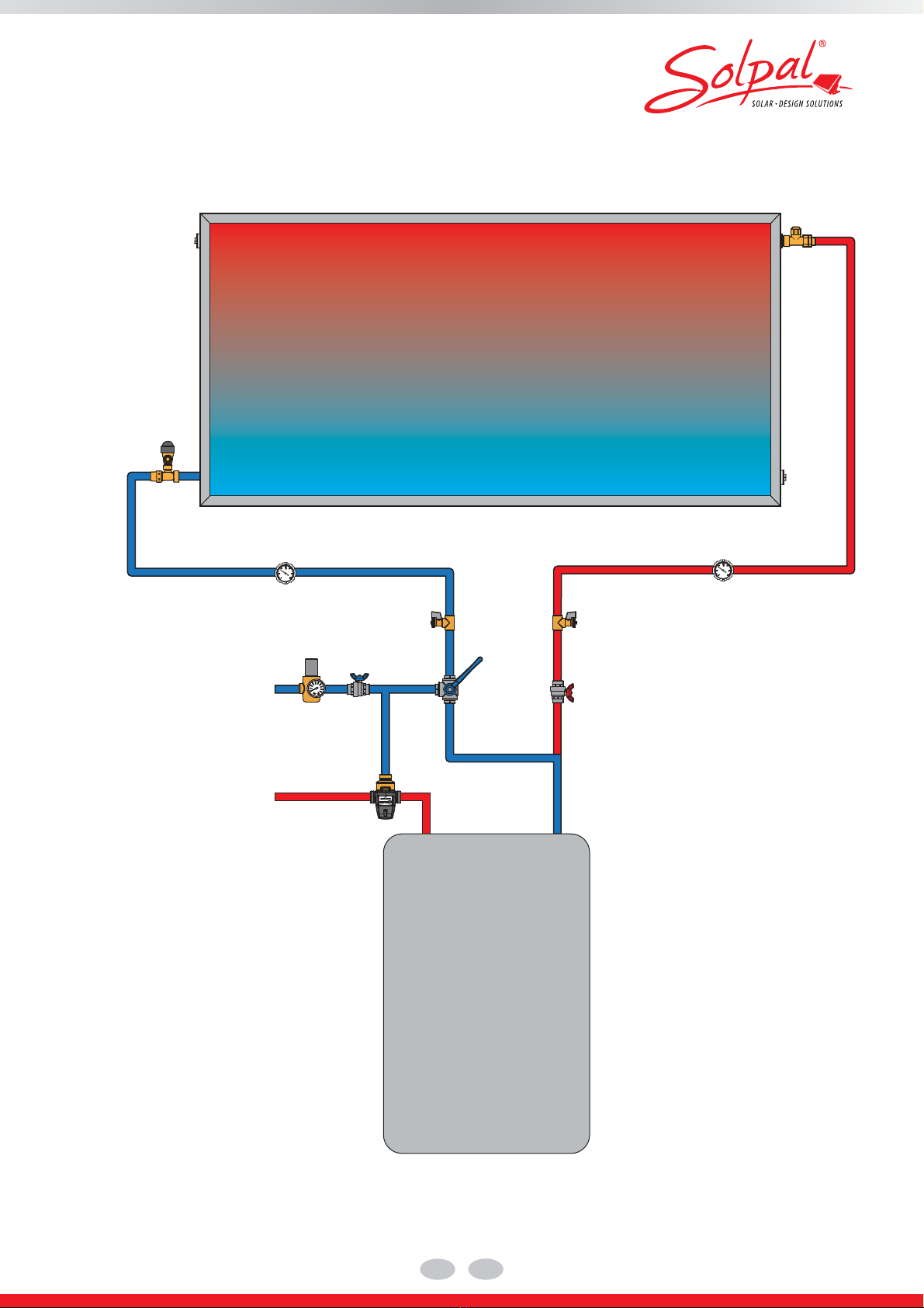
Hydraulic Connection
Conexión hidráulica
* Material to be provided on-site
* Material a aportar por el cliente
TO AVOID SERIOUS BODILY INJURY OR DAMAGE, ALL COMPONENTS SHOWN IN THE DRAWING ABOVE MUST BEINSTALLED.
PARA EVITAR GRAVES DAÑOS PERSONALES Y MATERIALES, ES NECESARIO MONTAR LOS COMPONENTES REPRESENTADOS EN EL ESQUEMA.
THE MAXIMUM OPERATING PRESSURE INTHE WATER CIRCUIT MUST BE LIMITED TO 60 PSI AT ALL TIMES.
INSTALL A PRESSURE REDUCER IF NECESSARY.
LA PRESIÓN DE SERVICIO MÁXIMA DEL CIRCUITO DE AGUA DEBE ESTAR LIMITADA EN TODO MOMENTO A 60 PSI.
UTILICE UN REDUCTOR DE PRESIÓN DE SER NECESARIO.
Stand alone
Instalación independiente
(Please note: this system is not SRCC certied
SRCC requires a backup heating , shown at
pages 11 to 13)
ES
EN
1*
Collector loop piping: (material: copper, operating temperature 220 °F or higher; diameter: not less than 3/4")
Collector loop pipe insulation: the cold and hot lines shall be insulated with a exible closed cell insulation with a minimum wall thickness of 1 inch.
Circuito de tuberías del captador (material: cobre, temperatura de funcionamiento 220 °F o más alta; diámetro no inferior a 3/4")
Aislamiento del circuito de tuberías del captador: las tuberías de agua fría y caliente deben estar aisladas con un aislamiento celular exible cerrado
con un grosor mínimo de 1 pulgada.
2Water lter
Filtro de agua 8Flexible connection (Flat sealing)
Connessione essibile (con junta plana)
3Pressure reducung valve (max. 60PSI)
Válvula de sobrepresión (máx. 60PSI) 9Anti Freeze Element 200 W (optional)
Elemento anti-congelación 200 W (opcional)
4Shut-o valve
Válvula de corte 10 Heating Element 2kW / 1kW (optional)
Varilla de calefacción 2kW / 1kW (opcional)
5Drain tap
Grifo de vaciado 11 Ventilation Valve
Válvula de ventilación
6Combined non-return/saftey valve
Válvula antirretorno/de seguridad combinada 12
Service water mixer (preset to max 140 °F)
(Exposed components are maintained below 140 °F or insulated/isolated)
Mezclador de agua caliente (preajustado a máx. 140 °F)
(Los componentes expuestos se mantienen por debajo de 140 °F o aislados)
7Expansion tank, 6 gallons
Vaso de expansión, 6 galeónes
Please note that a thread adapter (see page 5, part 6.4) has to be
used for American NPT threads in combination with Solpal connec-
tions and valves.
Recuerde que se debe utilizar un adaptador de rosca (véase página 5, parte
6.4) para las roscas NPT americanas en combinación con las conexiones y
válvulas de Solpal.
* ... To protect the system for inconsistent pressure or pressure damage we recommend using an expansion vessel.
* ... Para evitar variaciones de presión así como para proteger el equipo de daños se recomienda instalar un vaso de expasión.
5
4
4
2
7
9
10
12
8
bar
0
1
28
9
5
10
346
7
8
3
1
11
A
max. 60 PSI
72 PSI
max. 40 inch
6

12
Overview of components
Lista de componentes
EN ES
1
SAFETY VALVE
This valve is a pressure release
mechanisms used in pressure
systems. It has a non-return valve
integrated. The use of these valves is
strictly required due to safety
regulations. The safety valve opens at
a pressure of psi to reduce excess
pressure.
Recommended safety valve with
non-return for water heater:
¾", opening at PSI pressure
UV- resistant,
Material: hot molded BRASS UNI EN
12165CW617N, nickel plated surface
max. working temperature: 250°F
VÁLVULA DE SEGURIDAD
Esta válvula es un mecanismo de
alivio de presión utilizado en sistemas
de presión. Lleva una válvula
antirretorno integrada.
Es estrictamente necesario utilizar
estas válvulas por los reglamentos de
seguridad. La válvula de seguridad se
abre a una presión de 72 psi para
reducir el exceso de presión.
Válvula de seguridad con válvula
antirretorno integrada para
calentador de agua:
¾", apertura a una presión de 72 PSI,
resistente a los rayos UV,
material: LATÓN UNI EN
12165CW617N moldeado en caliente,
superficie niquelada, temperatura máx.
de trabajo: 250°F
2
VENTILATION VALVE
This valve ensures that no vacuum is
created when draining the water tank.
In the event of negative pressure, the
ventilation valve automatically supplies
the system with air.
Recommended ventilation valve:
¾", with DN15 solar neoperl backflow
preventer, UV-resistant
Material: brass
max. working temperature: 250°F
VÁLVULA DE VENTILACIÓN
Esta válvula asegura que no se forme
vacío al vaciar el acumulador de agua.
En el caso de que la presión sea
negativa, la válvula de ventilación
suministra aire automáticamente al
sistema.
Válvula de ventilación
recomendada:
¾", con válvula solar contra reflujo
DN15 neoperl,
resistente a los rayos UV,
material: latón,
temperatura máx. de trabajo: 250°F
3
COLD WATER SUPPLY ISOLATION
VALVE
This valve should stay open to allow
water from the public water system
to fill the Solpal water tank. When this
valve is closed, the Solpal and
the supplemental water heater are
disconnected from the pressurized
mains of the public water system.
Recommended ball valve:
¾" fully ported Brass Ball Valve for
heating, plumbing, and industrial
applications
max. safe operating pressure 600 psi
temperature Range up to 250° F
VÁLVULA DE AISLAMIENTO DE
ALIMENTACIÓN DE AGUA FRÍA
Esta válvula debe permanecer abierta
para que el agua de la red pública
pueda llenar el acumulador de agua
del Solpal. Cuando la válvula está
cerrada, el Solpal y el calentador de
agua suplementario están
desconectados de la red presurizada
del sistema público de agua.
Válvula de bola recomendada:
Válvula de bola de latón de ¾" de paso
total para calefacción, fontanería y
aplicaciones industriales, presión de
servicio máx. de seguridad 600 psi,
rango de temperatura hasta 250 °F
4
HOT WATER SUPPLY ISOLATION
VALVE
Keep this valve open to assure that hot
water can drain or escape in case of
overheating. This valve can temporarily
be closed for maintenance purposes.
Recommended ball valve:
¾" fully ported Brass Ball Valve for
heating, plumbing, and industrial
applications
max. safe operating pressure 600 psi
temperature range up to 250° F
VÁLVULA DE AISLAMIENTO DE
ALIMENTACIÓN DE AGUA
CALIENTE
Mantenga esta válvula abierta para
que el agua caliente se pueda drenar o
pueda escapar en caso de
sobrecalentamiento. La válvula se
puede tener temporalmente cerrada
para fines de mantenimiento.
Válvula de bola recomendada:
Válvula de bola de latón de ¾" de paso
total para calefacción, fontanería y
aplicaciones industriales, presión de
servicio máx. de seguridad 600 psi,
rango de temperatura hasta 250 °F
5
DRAIN VALVE
This boiler drains are normally closed
and capped. Use these valves to drain
the Solpal. Attach a garden hose to
both drain valves. Terminate the hoses
in either a service basin or an
appropriate spot outside the house.
Open both boiler drains at once to
drain the unit. WARNING: WATER
MAY BE DISCHARGED AT VERY
HIGH TEMPARATURES. TO AVOID
SCALDING, EXERCISE MAXIMUM
CAUTION WHEN DRAINING THE
HOT WATER FROM THE SOLPAL.
DO NOT POINT HOSE AT PERSONS
OR PETS. ALWAYS DISCHARGE
THE HOT WATER TO A SAFE
PLACE.
Recommended drain valve:
¾" unibody ball valve
max. temperature: 250°F
Standard Port Opening
with hose union and cap delivered
separately
VÁLVULA DE DRENAJE
Estos drenajes de la caldera suelen
estar cerrados y tapados. Utilice estas
válvulas para drenar el Solpal. Fije una
manguera de jardín a ambas válvulas
de drenaje. Coloque los extremos en
un lavabo de servicio o en un lugar
apropiado fuera de la casa. Abra
ambos drenajes de la caldera al mismo
tiempo para frenar la unidad.
AVISO: EL AGUA SE PUEDE SALIR
A TEMPERATURAS MUY ALTAS.
PARA EVITAR ESCALDADURAS,
PROCEDA CON LA MÁXIMA
PRECAUCIÓN AL DRENAR EL
AGUA CALIENTE DEL SISTEMA
SOLPAL. NO APUNTE CON LA
MANGUERA A PERSONAS NI
ANIMALES. DESCARGUE SIEMPRE
EL AGUA CALIENTE EN UN LUGAR
SEGURO.
Válvula de drenaje recomendada:
Válvula de bola ¾" Unibody,
temperatura máx.: 250 °F, apertura de
boca estándar, con unión de manguera
y tapa, se suministra por separado
6
THERMOSTATIC MIXING VALVE
This valve controls the temperature of
the warm water output. According to
local standards the valve must have a
scald safe function. Scald safe means
that in the case of a cold water failure,
the hot water supply shuts off
automatically.
Recommended mixing valve:
ESBE VTA 322, 95 - 140°F, G 1”,
PN10
_____________________________
External thread, ISO 228/1
VÁLVULA MEZCLADORA
TERMOSTÁTICA
Esta válvula controla la temperatura de
la salida del agua caliente. En
conformidad con la normativa local, la
válvula debe tener una función de
protección contra las escaldaduras.
Esto significa que en caso de que se
produzca un fallo de agua fría, el
suministro de agua caliente se cierre
automáticamente.
Válvula mezcladora recomendada:
ESBE VTA 322, 95 - 140°F, G 1”,
PN10
_____________________________
Rosca exterior, ISO 228/1
7
PRESSURE REDUCING VALVE
This valve should ensure a constant
output pressure of 60 psi independent
of the input pressure delivered from
any source.
Recommended pressure reducing
valve:
Honeywell D06F-1A, G 1",
brass, dezincification resistant
Pressure setpoint range: 20 to 90 psi
VÁLVULA REDUCTORA DE
PRESIÓN
Esta válvula debe asegurar una
presión de salida constante de 60 psi
independientemente de la presión de
entrada de cualquier fuente.
Válvula reductora de presión
recomendada:
Honeywell D06F-1A, G 1", latón,
resistente a la antidezincificación,
rango de ajuste de presión: 20 a 90 psi
8
3 WAY BALL VALVE
This valve provides solar system cold
water shut off without interrupting
normal cold water service.
Recommended 3-way ball valve:
Honeywell ¾" 3-way globe mixing
valve, V5013N
max. pressure: 240 psi
Material: Brass
temperature Range: up to 250°F
threaded (IPS)
VÁLVULA DE BOLA DE 3 VÍAS
Esta válvula permite cerrar el agua fría
del sistema solar sin interrumpir el
servicio normal de agua fría.
Válvula de bola de 3 vías
recomendada:
Válvula mezcladora de 3 vías
Honeywell de ¾" de paso recto,
V5013N, presión máx.: 240 psi,
material: latón, rango de temperatura:
hasta 250°F, roscada (IPS)
9
Thermometer
To determine whether the solar system
is working, it is necessary to install a
thermometer.
Recommended thermometer:
Temperature Range: 32 °F to 250 °F
Termómetro
Para comprobar si el sistema solar
está funcionando, es necesario instalar
un termómetro.
Termómetro recomendado:
Rango de temperatura: 32 °F a 250 °F
72
72
ES
EN

13
Hydraulic Connection
Conexión hidráulica
Pre-heater tankless gas
Precalentador de paso a gas
Auxilliary Water Heating Equipment
Auxilliary water heater must have adequate capacity, listed and labeled by an accredited listing organization
Equipo auxiliar de calentamiento de agua
El equipo auxiliar de calentamiento de agua debe tener el volumen adecuado, listado y etiquetado por un
órgano de listado acreditado.
2
1
5B
4
6
8
7
5A
3
9b
9a
cold water inlet
entrada de agua fría
hot water outlet
salida de agua caliente
ES
EN
14
Pre-heater gas boiler
Precalentador con caldera de gas
Hydraulic Connection
Conexión hidráulica
2
1
5B
4
8
7
5A
6
9b9a
cold water inlet
entrada de agua fría
hot water outlet
salida de agua caliente
Auxilliary Water Heating Equipment
Auxilliary water heater must have adequate
capacity, listed and labeled by an accredited
listing organization
Equipo auxiliar de calentamiento de agua
El equipo auxiliar de calentamiento de agua
debe tener el volumen adecuado, listado y
etiquetado por un órgano de listado acreditado.
ES
EN
3

15
cold water inlet
entrada de agua fría
hot water outlet
salida de agua caliente
Hydraulic Connection
Conexión hidráulica
Pre-heater electric boiler
Precalentador eléctrico con caldera
Auxilliary Water Heating Equipment
Auxilliary water heater must have adequate capacity, listed and labeled by an accredited listing organization
Equipo auxiliar de calentamiento de agua
El equipo auxiliar de calentamiento de agua debe tener el volumen adecuado, listado y etiquetado por un órgano de
listado acreditado.
ES
EN
2
1
5B
48
7
5A
6
3
9b9a

16
Flat Roof Installation
Montaje en tejado plano
1
1a
1b
1c
213
2b
2d
2a
2c
2d
2a
2b
2c
2.1
1.1 4.1
3.1
1.2
THE FOLLOWING STEPS MUST
BE PERFORMED BY A LICENSED ROOFING CONTRACTOR
LOS SIGUIENTES TRABAJOS DEBEN SER REALIZADOS POR UN
CONTRATISTA DE TECHOS HOMOLOAGADO
TO AVOID BODILY HARM AND/OR
PROPERTY DAMAGE, HAVE TWO PERSONS
JOINTLY INSTALL THE PRODUCT.
FRAGILE PRODUCT – HANDLE WITH CARE!
PARA EVITAR GRAVES DAÑOS PERSONALES
Y/O MATERIALES, EL PRODUCTO DEBE SER
INSTALADO ENTRE DOS PERSONAS.
¡PRODUCTO FRÁGIL – MANEJAR CON CUIDADO
Attach the four mounting brackets to the right and left collector legs
Fije los cuatro soportes de montaje a las patas derecha e izquierda del captador
COLLECTOR LEGS MAY HAVE SHARP EDGES. HANDLE WITH CARE TO AVOID BODILY HARM AND/OR PROPERTY DAMAGE.
LAS PATAS DEL CAPTADOR PUEDEN TENER BORDES AFILADOS. MANÉJENSE CON CUIDADO PARA EVITAR DAÑOS PERSONALES Y/O MATERIALES.
ES
EN

17
4
4.1
2.2
2.2
4.1
3.1
4b
4a
4c
4d
90°
4a-4d
3
18 ft/lb
Two persons are required for this procedure: One person
should tilt the product slowly while the second person should
attach the collector legs using the special metric T-head bolts.
Move the metric T-head bolt in a 90 degree
angle as shown in the diagram.
Gire el tornillo métrico de cabeza en T 90 grados tal y
como se muestra en el diagrama
Flat Roof Installation
Montaje en tejado plano
Para este procedimiento se precisan dos personas:
Laprimerapersona debe inclinar lentamente el pro-
ducto,mientraslasegundajalaspatasdelcaptador
con los tornillos métricos especiales de cabeza en T.
Ensure that the collector leg
is stabilized and secured.
Asegúrese de que la pata del
colector está estabilizada y ja.
Tighten all four bolts with a torque of 18 ft lb
Apriete los cuatro tornillos con un par de 18 ft lb
ES
EN

18
Flat Roof Installation
Montaje en tejado plano
5
66a-6d
6b
6c
6d
6a
Make sure that the bottom edge of the product touches the surface for support
Asegúrese de que el borde inferior toca la supercie del producto.
Mark the attachment points.
Make sure the collector legs are parallel.
Marque los puntos de jación.
Asegúrese de que las patas del captador están paralelas.
ES
EN

19
Flat Roof Installation
Montaje en tejado plano
7
7a
814
8a/8b
Ø14
8a 8b
Carefully move product. Drill holes.
Put product back and attach to roof surface.
Mueva el producto con cuidado Taladre los agujeros.
Coloque el producto encima de los agujeros y fíjelo al tejado.
ES
EN

20
6.1
< 30 ft lb
< 30 ft lb
WARNING WARNING
6.1
6.1
6.1
6.1
13
12
11
10
6.1
6.1
6.3
6.1
6.2
Flat Roof Installation
Montaje en tejado plano
918 ft/lb
9b
9a
9b
M12x80
Securely tighten the four bolts with a torque of 18 ft lb
Apriete los cuatro tornillos con un par de 18 ft lb
Connect the cold water inlet and ll the collector
Conecte la entrada de agua fría y llene el captador
Connect the hot water outlet
Conecte la salida de agua caliente
TO AVOID DAMAGE, DO NOT INSULATE VALVES!
PARA EVITAR DAÑOS, NO AÍSLE LAS VÁLVULAS.
Please use the thread adaptors
for US - NPT threads!
Do not use more
than 30 ft/lb tourque!
Do not use more
than 30 ft/lb tourque!
Retire la lámina en los 14 días siguientesa la instalación de Solpal
but never before the system is lled!
ES
EN
Remove the foil within 14 days of installing the Solpal
but never before the system is lled!
5
Table of contents
Languages:
Popular Heater manuals by other brands

Alarko
Alarko ADA Operation manual

TERMOFOL
TERMOFOL TF750W Installation & operation instructions

Frico
Frico Thermozone ADA Cool Mounting and assembly instruction

Kambrook
Kambrook KCE340GRY Instruction booklet

Tylö
Tylö SO 6 Installation and operating instructions

Dyna-Glo
Dyna-Glo RMC-KFA65TDLX, RMC-KFA120TDLX,... user manual

EdenPURE
EdenPURE Classic CopperPLUS A5946 instructions

Biddle
Biddle Forceflow 900 Series Installation, operating, & maintenance instructions

Convair
Convair CTH02 Owner's instruction manual

Vivax
Vivax QH-1800S user manual

Strend Pro
Strend Pro KV-011 instruction manual

Marley
Marley K404A Installation & maintenance instructions


