OM-626 Page 5
SECTION 1 –CONSIGNES DE SECURITE –LIRE AVANT
UTILISATION
som _nd_fre 5/97
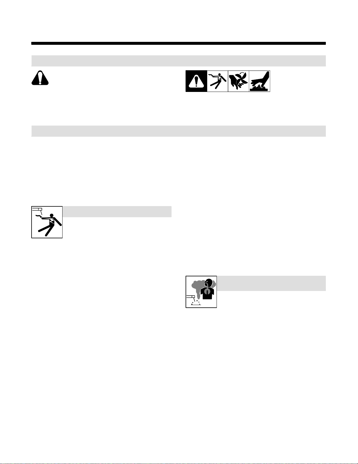
1-1. Signification des symboles
SignifieMise en garde ! Soyez vigilant ! Cette procédure
présente des risques de danger ! Ceux-ci sont identifiés
par des symboles adjacents aux directives.
YIdentifie un message de sécuritéparticulier.
.Signifie NOTA ; n’est pas relatif àla sécurité.
Ce groupe de symboles signifie Mise en garde ! Soyez vigilant ! Il y a des
risques de danger reliés aux CHOCS ÉLECTRIQUES, aux PIÈCES EN
MOUVEMENT et aux PIÈCES CHAUDES. Reportez-vous aux symboles
et aux directives ci-dessous afin de connaître les mesures àprendre pour
éviter tout danger.
1-2. Dangers relatifs au soudage àl’arc
YLes symboles présentés ci-après sont utilisés tout au long du
présentmanuel pour attirer votre attention et identifier les risques
de danger. Lorsque vous voyez un symbole, soyez vigilant et
suivez les directives mentionnées afin d’éviter tout danger. Les
consignes de sécuritéprésentées ci-après ne font que résumer
l’information contenue dans les normes de sécuritéénumérées
àla section 1-4. Veuillez lire et respecter toutes ces normes de
sécurité.
YL’installation, l’utilisation, l’entretien et les réparations ne doi-
vent être confiés qu’à des personnes qualifiées.
YAu cours de l’utilisation, tenir toute personne àl’écart et plus par-
ticulièrement les enfants.
UN CHOC ÉLECTRIQUE peut tuer.
Un simple contact avec des pièces électriques peut
provoquerune électrocution ou des blessures graves.
L’électrode et le circuit de soudage sont sous tension
dès que l’appareil est sur ON. Le circuit d’entrée et les
circuits internes de l’appareil sont également sous
tension àce moment-là. En soudage semi-automatique ou automatique,
le fil, le dévidoir, le logement des galets d’entraînement et les pièces
métalliques en contact avec le fil de soudage sont sous tension. Des
matériels mal installés ou mal mis àla terre présentent un danger.
DNe jamais toucher les pièces électriques sous tension.
DPorter des gants et des vêtements de protection secs ne comportant
pas de trous.
DS’isoler de la pièce et de la terre au moyen de tapis ou d’autres
moyens isolants suffisamment grands pour empêcher le contact phy-
sique éventuel avec la pièce ou la terre.
DNe pas se servir de source électrique àcourant électrique dans les zones
humides, dans les endroits confinés ou làoùon risque de tomber.
DSe servir d’une source électrique àcourant électrique UNIQUEMENT si le
procédéde soudage le demande.
DSi l’utilisation d’une source électrique àcourant électrique s’avère néces-
saire, se servir de la fonction de télécommande si l’appareil en est équipé.
DCouper l’alimentation ou arrêter le moteur avant de procéder àl’instal-
lation, àla réparation ou àl’entretien de l’appareil. Déverrouiller
l’alimentationselon la norme OSHA 29 CFR 1910.147 (voir normes de
sécurité).
DInstaller et mettre àla terre correctement cet appareil conformément à
son manuel d’utilisation et aux codes nationaux, provinciaux et
municipaux.
DToujours vérifier la terre du cordon d’alimentation –Vérifier et s’assu-
rer que le fil de terre du cordon d’alimentation est bien raccordéàla
bornede terre du sectionneur ou que la fiche du cordon est raccordée
àune prise correctement mise àla terre.
DEn effectuant les raccordements d’entrée fixer d’abord le conducteur
de mise àla terre appropriéet contre-vérifier les connexions.
DVérifier fréquemment le cordon d’alimentation pour voir s’il n’est pas
endommagéou dénudé–remplacer le cordon immédiatement s’il est
endommagé–un câble dénudépeut provoquer une électrocution.
DMettre l’appareil hors tension quand on ne l’utilise pas.
DNe pas utiliser des câbles usés, endommagés, de grosseur insuffi-
sante ou mal épissés.
DNe pas enrouler les câbles autour du corps.
DSi la pièce soudée doit être mise àla terre, le faire directement avec un
câble distinct –ne pas utiliser le connecteur de pièce ou le câble de
retour.
DNe pas toucher l’électrode quand on est en contact avec la pièce, la
terre ou une électrode provenant d’une autre machine.
DN’utiliser qu’un matériel en bon état. Réparer ou remplacer sur-le-
champ les pièces endommagées. Entretenir l’appareil conformément
àce manuel.
DPorter un harnais de sécuritéquand on travaille en hauteur.
DMaintenir solidement en place tous les panneaux et capots.
DFixer le câble de retour de façon àobtenir un bon contact métal-métal
avec la pièce àsouder ou la table de travail, le plus près possible de la
soudure.
DIsoler la pince de masse quand pas mis àla pièce pour éviter le contact
avec tout objet métallique.
Il y a DU COURANT CONTINU IMPORTANT dans les
convertisseurs après la suppression de l’alimenta-
tion électrique.
DArrêter les convertisseurs, débrancher le courant électrique, et dé-
charger les condensateurs d’alimentation selon les instructions
indiquées dans la partie entretien avant de toucher les pièces.
Le soudage génère des fumées et des gaz. Leur
inhalation peut être dangereux pour votre santé.
DEloigner votre tête des fumées. Ne pas respirer
les fumées.
DA l’intérieur, ventiler la zone et/ou utiliser un échappement au niveau
de l’arc pour l’évacuation des fumées et des gaz de soudage.
DSi la ventilation est insuffisante, utiliser un respirateur àalimenta-
tion d’air homologué.
DLire les spécifications de sécuritédes matériaux (MSDSs) et les
instructions du fabricant concernant les métaux, les consomma-
bles, les revêtements, les nettoyants et les dégraisseurs.
DTravailler dans un espace ferméseulement s’il est bien ventiléou en
portant un respirateur àalimentation d’air. Demander toujours àun
surveillant dûment forméde se tenir àproximité. Des fumées et des
gaz de soudage peuvent déplacer l’air et abaisser le niveau d’oxy-
gène provoquant des blessures ou des accidents mortels. S’assu-
rer que l’air de respiration ne présente aucun danger.
DNe pas souder dans des endroits situés àproximitéd’opérations de
dégraissage, de nettoyage ou de pulvérisation. La chaleur et les
rayons de l’arc peuvent réagir en présence de vapeurs et former des
gaz hautement toxiques et irritants.
DNe pas souder des métaux munis d’un revêtement, tels que l’acier
galvanisé, plaquéen plomb ou au cadmium àmoins que le revête-
ment n’ait étéenlevédans la zone de soudure, que l’endroit soit bien
ventilé, et si nécessaire, en portant un respirateur àalimentation
d’air. Les revêtements et tous les métaux renfermant ces éléments
peuvent dégager des fumées toxiques en cas de soudage.
LES FUMÉES ET LES GAZ peuvent
être dangereux.