Solplanet ASW0400/1250A-S User manual

User Manual
Single phase All-in-one
hybrid energy storage system
ASW0400/1250A-S
ASW0600/1250A-S
ASW0800/1250A-S
ASW1000/1250A-S
ASW0400/2500A-S
ASW0600/2500A-S
ASW0800/2500A-S
ASW1000/2500A-S

Contents
1 General information....................................................................
1.1 About this document................................................................................
1.2 Product validity.........................................................................................
1.3 Target group.............................................................................................
1.4 Symbols....................................................................................................
2 Safety........................................................................................
2.1 Intended use............................................................................................
2.2 Important safety instructions..................................................................
2.3 Symbols on the label...............................................................................
3 Unpacking and storage.............................................................
3.1 Scope of delivery.....................................................................................
3.2 Product storage......................................................................................
4 Inverter overview......................................................................
4.1 Product description.................................................................................
4.2 Dimensions.............................................................................................
4.3 Display.....................................................................................................
4.3.1 Overview of the panel.....................................................................
4.3.2 Screen............................................................................................
4.4 Interfaces and functions.........................................................................
4.5 System solution.......................................................................................
4.5.1 System solution..............................................................................
4.5.2 System wiring diagram..................................................................
4.6 Energy Management..............................................................................
5 Mounting...................................................................................
5.1 Requirements for mounting.....................................................................
1
1
1
1
2
3
3
4
6
7
7
7
8
8
9
9
9
10
11
13
13
14
17
21
21

6 Electrical connection.................................................................
6.1 Connection port description.....................................................................
6.2 Connecting additional grounding.............................................................
6.3 AC connection..........................................................................................
6.3.1 Requirements for the AC connection.............................................
6.3.2 AC cable connection......................................................................
6.3.3 Connecting the AC connectors......................................................
6.4 DC connection.........................................................................................
6.4.1 Requirements for the DC connection.............................................
6.4.2 Assembling the DC connectors......................................................
6.4.3 Connecting the PV array................................................................
6.5 Communication equipment connection..................................................
6.5.1 Communication ports.....................................................................
6.5.2 Communication cable connection.................................................
7 Commissioning and operating...................................................
7.1 Inspection before commissioning.............................................................
7.2 Commissioning procedure........................................................................
7.3 Checking the operating status..................................................................
7.4 Congure the parameter on the screen....................................................
8 Solplanet app.............................................................................
8.1 Brief introduction......................................................................................
8.2 Download and install................................................................................
8.3 Create an account....................................................................................
8.4 Create a plant...........................................................................................
8.5 Setting parameters...................................................................................
8.5.1 Inverter conguration.....................................................................
8.5.2 Grid code settings..........................................................................
8.5.3 Active power reduction at overfrequency P(f)...............................
8.5.4 Active power reduction at overvoltage P(U)..................................
8.5.5 Cosφ(P) curve conguration.........................................................
8.5.6 Q(U) curve conguration................................................................
23
23
23
25
25
26
29
29
29
30
32
34
34
35
37
37
37
38
39
41
41
41
41
43
50
50
51
52
55
59
62

9 Decommissioning the product...................................................
9.1 Disconnecting the inverter from voltage sources....................................
10 Technical data..........................................................................
10.1 ASW 0400-1000/1250A-S.......................................................................
10.2 ASW 0400-1000/2500A-S.....................................................................
10.3 General data...........................................................................................
10.4 Protective device....................................................................................
11 Troubleshooting ........................................................................
12 Maintenance.............................................................................
13 Recycling and disposal..............................................................
14 EU declaration of conformity....................................................
15 Service and warranty................................................................
16 Contact.....................................................................................
65
65
67
67
71
75
76
77
81
82
82
83
84

This document describes the mounting, installation, commissioning, conguration, operation,
troubleshooting and decommissioning of the single phase All-in-one hybrid energy storage
system (HESA).
You will nd the latest version of this document and further information on the HESA in PDF
format at www.solplanet.net.
It is recommended that this document be readily accessible at all times.
1.1 About this document
This document is valid for the following models:
1.2 Product validity
This document is intended for electricians and users who have basic safety knowledge about
operating electrical equipment. However, installation personnel must be familiar with local
requirements and regulations.
Users must possess the following skills:
•Know how the machine works and operates.
•Train how to deal with the hazards and risks associated with installing, repairing and using
electrical equipment and installations.
1.3 Target group
•ASW0400/1250A-S
•ASW0600/1250A-S
•ASW0800/1250A-S
•ASW1000/1250A-S
•ASW0400/2500A-S
•ASW0600/2500A-S
•ASW0800/2500A-S
•ASW1000/2500A-S
UM0045_ASW0400/1250A-1000/2500A-S_EN_V01_0723
1
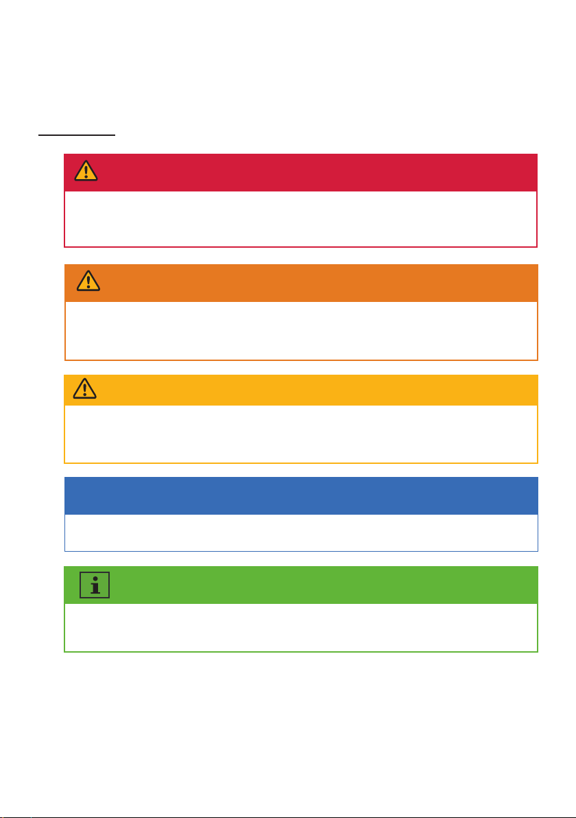
1.4 Symbols
Information that is important for a specic topic or goal, however not related to
safety.
•Be aware of all applicable laws, standards and directives.
•Understand and comply with this document and all safety information.
!
Indicates a hazardous situation which, if not avoided, will result in death or serious
injury.
DANGER
!
Indicates a hazardous situation which, if not avoided, could result in death or
serious injury.
WARNING
!
Indicates a hazardous situation which, if not avoided, could result in minor or
moderate injury.
CAUTION
Indicates a situation which, if not avoided, can result in property damage.
NOTICE
UM0045_ASW0400/1250A-1000/2500A-S_EN_V01_0723
2

Safety2
2.1 Intended use
The product is a All-in-one hybrid energy storage system with 1 or 2 MPP trackers and a internal
battery connection that feeds the direct current of the PV array into the connected battery or
converts it to grid-compliant single-phase current and then feeds it into the utility grid. The
product also can convert the direct current supplied by the battery into grid-compliant
single-phase current. The product has a backup function that can continue to supply the load
with power from the battery or PV system in the event of a grid fault after the customer’s inhouse
main power switch is o.
The product is intended for indoor applications. Do not use in outdoor applications!
The product is equipped with an integrated high frequency transformer and therefore has galvan-
ic isolation. The product should not be operated with PV modules which require functional
grounding of either the positive or negative PV conductors.
All components must remain within their permitted operating ranges and their installation
requirements at all times.
Use the product only in accordance with the information provided in the user manual and with the
locally applicable standards and directives. Any other application may cause personal injury or
damage to property.
The product must only be used in countries for which it is approved by solplanet and the grid
operator.
The type label must be permanently attached to the product and must be in a legible condition.
This document does not replace any regional, state, provincial, federal or national laws, regula-
tions or standards that apply to the installation, electrical safety and use of the product.
UM0045_ASW0400/1250A-1000/2500A-S_EN_V01_0723
3

The product has been designed and tested strictly according to the international safety require-
ments. As with all electrical or electronical devices, there are residual risks despite careful
construction. To prevent personal injury and property damage and to ensure long-term operation
of the product, read this section carefully and observe all safety information at all times.
2.2 Important safety instructions
WARNING
Danger to life due to electric shock from destruction of the
measuring device due to overvoltage!
Overvoltage can damage a measuring device and result in voltage being present in the
enclosure of the measuring device. Touching the live enclosure of the measuring device
results in death or lethal injuries due to electric shock.
•Only use measuring devices with the measurement range higher than the grid voltage.
DANGER
Danger to life due to electric shock when touching live com-
ponents in backup mode!
Even if the AC breaker are disconnected, the parts of the system may still be live when the
battery is switched on due to backup mode.
•Do not open the product.
•Disconnect the product from all voltage and energy sources and ensure it can not be reconnected
before working on the product.
DANGER
Danger to life due to re or explosion when batteries are fully
discharged!
A re may occur due to incorrect charging of fully discharged batteries. This can result in
death or serious injury.
•Make sure that the battery is not fully discharged before commissioning the system.
•Contact the battery manufacturer for further proceedings if the battery is fully discharged.
•The battery in the product need be charged if the product has been stored more than half a year.
UM0045_ASW0400/1250A-1000/2500A-S_EN_V01_0723
4
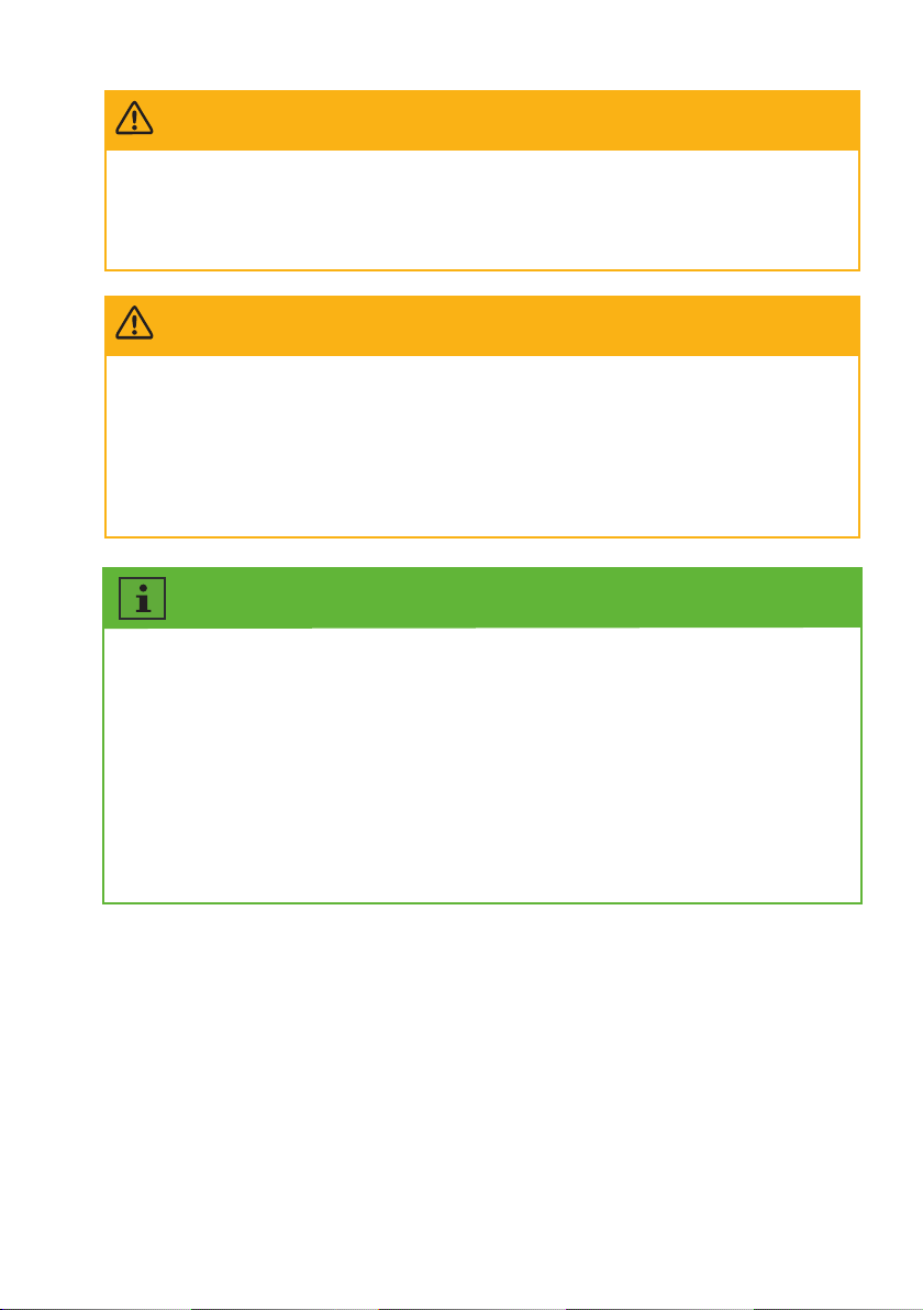
CAUTION
Risk of burns due to high temperature.
Some parts of the enclosure can become hot during operation.
•During operation, do not touch any parts other than the enclosure lid of the product.
CAUTION
Risk of injury due to weight of product.
Injuries may result if the product is lifted incorrectly or dropped while being transported or
mounted.
•Transport and lift the product carefully. Take the weight of the product into account.
•Wear suitable personal protective equipment for all work on the product.
The country grid code set must be set correctly.
If you select a country grid code set which is not valid for your country and purpose, it can
cause a disturbance in the PV system and lead to problems with the grid operator. When
selecting the country grid code set, you must always observe the locally applicable
standards and directives as well as the properties of the PV system (e.g. PV system size,
grid-connection point).
•If you are not sure which standards and directives are valid for your country or purpose, contact the
grid operator.
UM0045_ASW0400/1250A-1000/2500A-S_EN_V01_0723
5
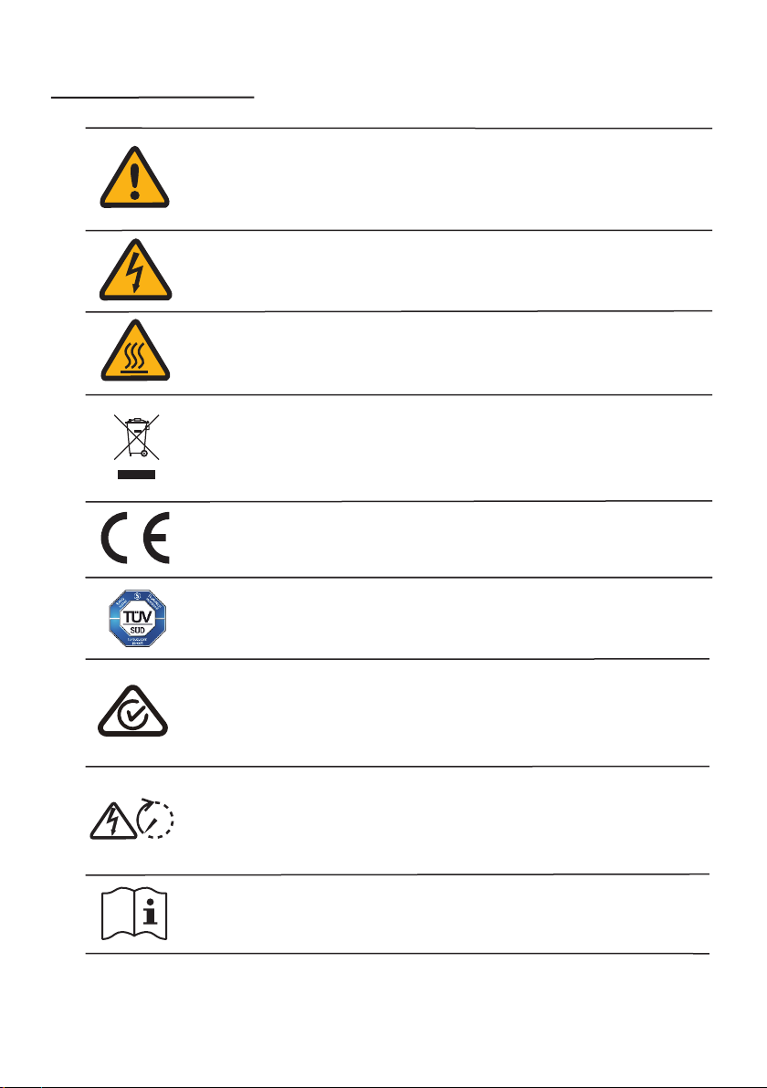
2.3 Symbols on the label
Beware of a danger zone!
This symbol indicates that the product must be additionally grounded if
additional grounding or equipotential bonding is required at the installation
site.
Beware of high voltage and operating current!
The product operates at a high voltage and current. Work on the product must
only be carried out by skilled and authorized personnel.
Beware of hot surfaces!
The product can get hot during operation. Avoid contact during operation.
CE marking
The product complies with the requirements of the applicable EU directives.
WEEE Designation
Do not dispose of the product together with household waste. Dispose the
product in accordance with local disposal regulations for electronic waste.
Observe the documentation
Read and understand all documentation supplied with the product.
Capacitor discharge
Danger to life due to high voltages in the inverter. Do not touch live parts
for 5 minutes after disconnection from the power sources.
CE marking
The product complies with the requirements of the applicable EU directives.
5mins
Certication mark
The product has been tested by TÜV and obtained the quality certication mark.
UM0045_ASW0400/1250A-1000/2500A-S_EN_V01_0723
6

Unpacking and storage3
3.1 Scope of delivery
3.2 Product storage
Check the scope of delivery for completeness and any visible external damage. Contact your
distributor if the scope of delivery is incomplete or damaged.
Suitable storage is required if the inverter is not installed immediately:
•Store the HESA in the original packing case.
•The storage temperature must be between -15°C to +55°C, and the storage relative humidity
must be between 0 and 95%, non-condensing.
•The packing with the product shall not be tilted or inverted.
•The product must be fully inspected and tested by professionals before it can be put into
operation, if it has been stored for half a year or more.
Document
×
1
All-in-one system ×1
External CT ×1
AC connector ×1
DC connector ×2/4
UM0045_ASW0400/1250A-1000/2500A-S_EN_V01_0723
7
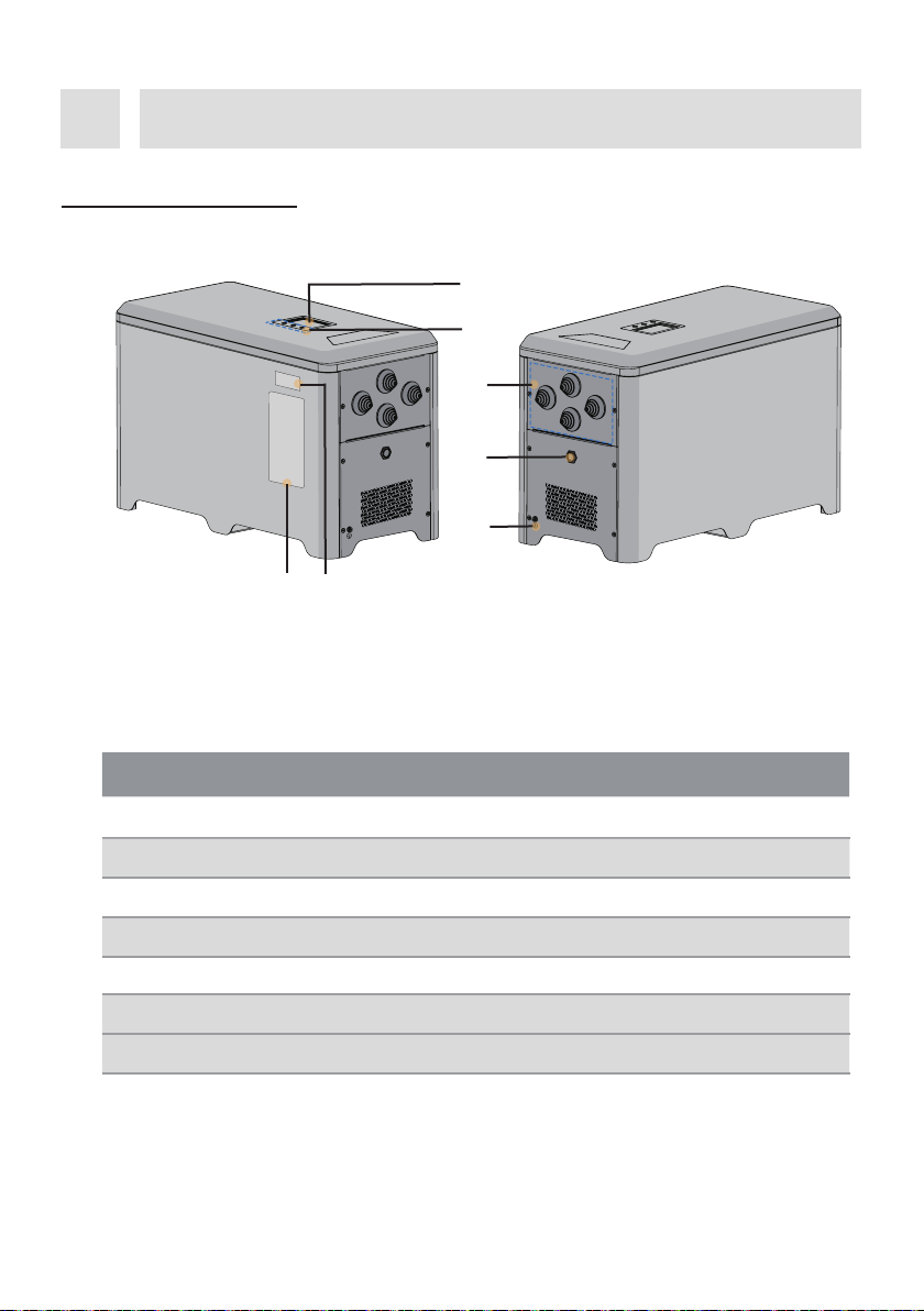
Inverter overview4
4.1 Product description
1
2
Object Description
Display screen
Button area
Wiring area
Battery button
Secondary grounding wire screw
WiFi stick QR code
Labels
1
2
3
4
5
6
7
67
3
4
5
Figure shown here is for reference only. The actual product received may dier!
UM0045_ASW0400/1250A-1000/2500A-S_EN_V01_0723
8

4.2 Dimensions
4.3 Display
4.3.1 Overview of the panel
The information provided here includes the operating parameters of all single phase All-in-one
hybrid energy storage system.
AB
Unit:mm
600
282
385
The machine is equipped with 1 display screen and 3 keys.
123
UM0045_ASW0400/1250A-1000/2500A-S_EN_V01_0723
9
4.3.2 Screen
The information provided here includes the operating parameters of all single phase All-in-one
hybrid energy storage system.
Mark NAME Function
Area
B
ADISPLAY / /
KEY
1
2
3
UP
DOWN
HOME
Adjust parameter selection or parame-
ter value upward.
Adjust parameter selection or parame-
ter value downward.
Click the HOME button to go to the next
level menu, or toggle parameter options
and parameter values.
Press the HOME button for a long time
to return to the upper-level menu.
Alarm, set parameters, and working sta-
tus display. See below.
Mode: Self-consumption
AC
600W
200W
×2
400W
Master
DC
1
11
8
2
37
9
6
10
4
12
5
UM0045_ASW0400/1250A-1000/2500A-S_EN_V01_0723
10

4.4 Interfaces and functions
The product is equipped with the following interfaces and functions:
Ai-Dongle
The product is equipped with an Ai-Dongle as standard, which provides a user interface for
conguring and monitoring the product. The Ai-Dongle can connect to the Internet via WLAN or
the Ethernet cable. If you don’t want to use Ai-Dongle, the Solplanet communication products or
the third-party monitor device can be chosen.
RS485 Interface
The product equipped with two external RS485 interfaces. The RS485 interfaces connected
through RJ45 ports.
RS485-1 and RS485-2 ports (see section 6.5.1): Two external RS485 interfaces used to the product
Object Description
PV strings model.
Household load.
The current state of the machine in parallel mode, there are two kinds:
master or slave.
Current operation mode.
Number of alarms.
Error or warning information.
Utility grid.
Power value, the arrow to the right indicates that power ows to the
grid, and vice versa indicates that power is taken from the grid.
The power value of the household load from the machine.
Battery charging and discharging power values, the arrow up means
discharge, and vice versa, charge.
The SOC information of the battery, 5 cells of charge represents 100%
SOC.
Output power of PV strings.
1
7
12
11
10
9
8
6
5
4
3
2
UM0045_ASW0400/1250A-1000/2500A-S_EN_V01_0723
11

parallel operation (see section 4.5.2). The control information of machines is exchanged through
the RS485 interfaces.
Current transformer (CT) interface
The CT is connected to the HESA through the RJ45 port (see section 6.5.1).
CAN (Controller Area Network) Interface
The product equipped with two external CAN interfaces and one internal CAN interfaces. The
CAN interfaces connected through RJ45 ports.
CAN-1 and CAN-2 ports (see section 6.5.1): Two external CAN interfaces used to the product
three-phase grid-connected mode operation used to the communication between each inverter
of the three-phase combinations (see section 4.5.2). The control information of three machines is
exchanged through the CAN interface. An internal CAN port is used to communicate with a
Battery Management System (BMS).
USB Interface
USB port is used to quickly upgrade programs via USB ash drive.
UM0045_ASW0400/1250A-1000/2500A-S_EN_V01_0723
12

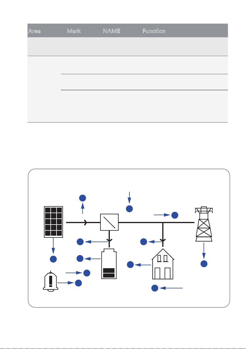
4.5 System solution
4.5.1 System solution
The single phase All-in-one hybrid energy storage system is composed of the following parts.
Item Description Remark
APV module
Supports to connect monocrystalline silicon module, polycrys-
talline silicon module, and thin-lm module without ground-
ing.
Inveter
BEnergy conversion (HESA).
D
GHI
J
K
F
E
A
Comminication
Power
Ethernet
B
C
UM0045_ASW0400/1250A-1000/2500A-S_EN_V01_0723
13
HInternet
ICloud server
J
Smart phone
K
Computer
GRouter The product can connect to router through Wi-Fi signal or
Ethernet cable.
The monitor information can transfer to Cloud Server through
Internet.
The monitor information is stored at cloud server.
The APP can be installed on the smart phone and then review
the monitor information.
The monitor information also can be review on the computer.
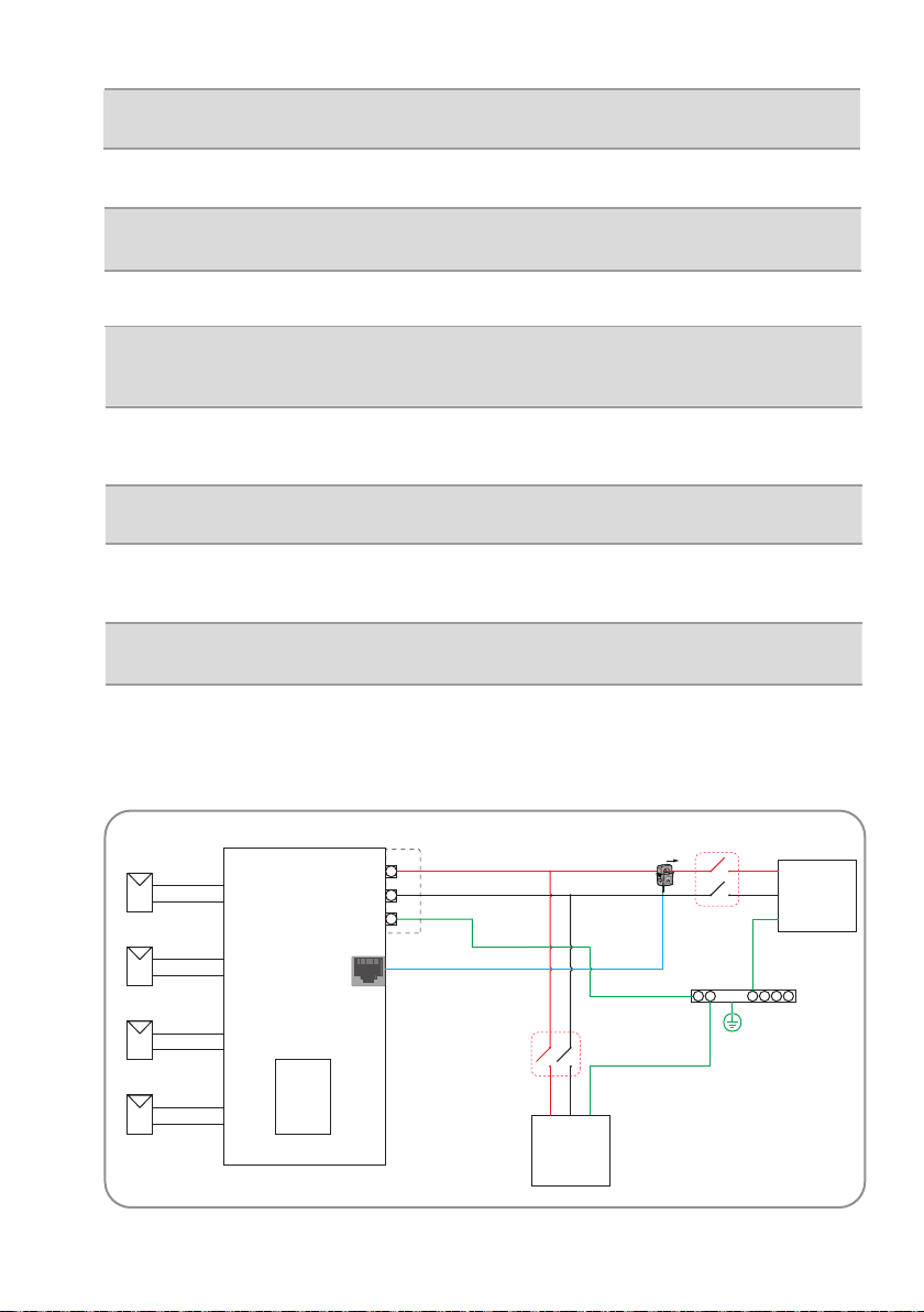
4.5.2 System wiring diagram
The connection line diagram of a single machine is shown below in Europe.
DCurrent
transformer (CT)
Measure the current and use for energy management.
EUtility grid
FLoad
CBattery Energy storage (Inside of HESA).
The product can connect to TN and TT grounding system grid.
General electrical equipment or EPS.
Normal
Loads
Grid
PV
PV
PV
PV
L
PV1+
PV1-
PV2+
PV2-
PV3+
PV3-
PV4+
PV4-
N
PE
PE-Bar
Battery
HESA
Switch
CT
CT
Positive
UM0045_ASW0400/1250A-1000/2500A-S_EN_V01_0723
14

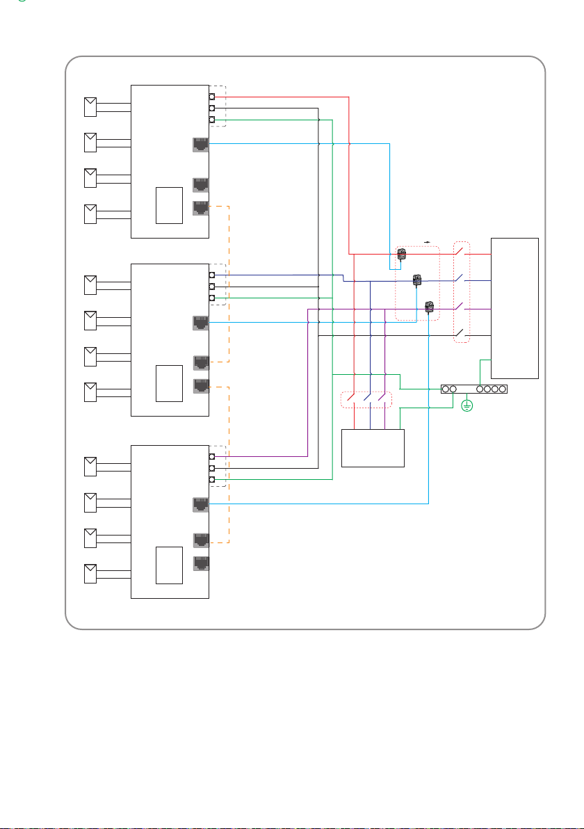
The connection line diagram of the machine parallel mode is shown below in Europe (up to three
machines in parallel mode).
Normal
Loads
Grid
PV
PV
PV
PV
L
PV1+
PV1-
PV2+
PV2-
PV3+
PV3-
PV4+
PV4-
N
PE
Battery
HESA
Switch
Switch
CT
CT 1 CT 2 CT 3
Positive
PV
PV
PV
PV
L
PV1+
PV1-
PV2+
PV2-
PV3+
PV3-
PV4+
PV4-
N
PE
Battery
HESA CT
RS485-1
RS485-2
RS485-1
RS485-2
RS485-1
RS485-2
PV
PV
PV
PV
L
PV1+
PV1-
PV2+
PV2-
PV3+
PV3-
PV4+
PV4-
N
PE
Battery
HESA CT
PE-Bar
UM0045_ASW0400/1250A-1000/2500A-S_EN_V01_0723
15
Three-phase
Normal load
Three-
phase Grid
PV
PV
PV
PV
L
PV1+
PV1-
PV2+
PV2-
PV3+
PV3-
PV4+
PV4-
N
PE
Battery
HESA
Switch
Switch
CT
CT 1
CT 2
CT 3
Positive
PV
PV
PV
PV
L
PV1+
PV1-
PV2+
PV2-
PV3+
PV3-
PV4+
PV4-
N
U
V
W
PE
Neutra
PE
Battery
HESA CT
CAN-1
CAN-2
CAN-1
CAN-2
CAN-1
CAN-2
PV
PV
PV
PV
L
PV1+
PV1-
PV2+
PV2-
PV3+
PV3-
PV4+
PV4-
N
PE
Battery
HESA CT
PE-Bar
UM0045_ASW0400/1250A-1000/2500A-S_EN_V01_0723
16
Other manuals for ASW0400/1250A-S
1
This manual suits for next models
7
Table of contents
Other Solplanet Storage manuals


Popular Storage manuals by other brands


Elo TouchSystems
Elo TouchSystems 15A2 for wireless card Quick installation guide for hard drive 80gb

Dell
Dell PowerVault MD3200 Series Getting started

CalDigit
CalDigit AV Pro instruction manual

IOGear
IOGear GHE225U user manual

ASUSTOR
ASUSTOR Drivestor 4 PRO Quick installation guide

Western Digital
Western Digital WDBAAH0015HCH - My Book Elite quick start