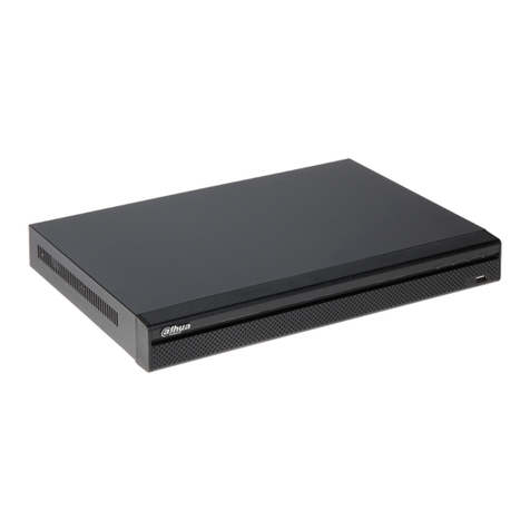
Solstice SLS-ECMS8 User manual

1SLS-ECMS8_SQ
9/25/13
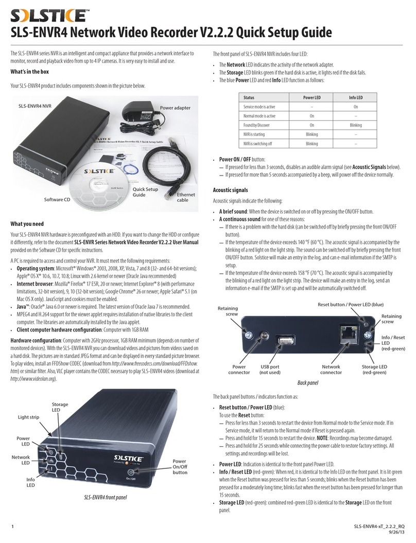
Status Power LED Info LED
Service mode is active – On
Normal mode is active On –
Found by Discover On Blinking
CMS is starting Blinking –
CMS is switching o Blinking –
• Power ON / OFF button:
—If pressed for less than 3 seconds, disables an audible alarm signal (see Acoustic signals
below).
—If pressed for more than 5 seconds accompanied by a beep, will power o the device normally.
Acoustic signals
Acoustic signals indicate the following:
• A brief sound: When the device is switched on or o by pressing the ON/OFF button.
• A continuous sound for one of these reasons:
—If there is a problem with the hard disk (can be switched o by briey pressing the front ON/OFF
button).
—If the temperature of the device exceeds 140 °F (60 °C). The acoustic signal is accompanied by
the blinking of a red light on the light strip. The sound can be switched o by briey pressing the
front ON/OFF button. Solstice will make an entry in the log, and can e-mail information if the
SMTP is setup.
—If the temperature of the device exceeds 158 °F (70 °C). The acoustic signal is accompanied by
the blinking of a red light on the light strip. The device will make an entry in the log, send an
information e-mail if the SMTP is set up and will be automatically switched o.
Back panel
Retaining
screw
Retaining
screw
Reset button / Power LED (blue)
Storage LED
(red-green)
Info / Reset
LED
(red-green)
Network
connector
USB port
(not used)
Power
connector
Back panel
The back panel buttons / indicators function as:
• Reset button / Power LED (blue):
To use the Reset button:
—Press for less than 3 seconds to restart the device from Normal mode to the Service mode. If in
Service mode, it will return to the Normal mode if Reset is pressed again.
—Press and hold for 15 seconds to restart the device. NOTE: Recordings may become damaged.
—Press and hold for 25 seconds while connecting the power cable to restore factory settings. All
settings and recordings will be lost.
• Power LED: Indication is identical to the front panel Power LED.
• Info / Reset LED (red-green): When red, it is identical to the Info LED on the front panel. It is lit green
when the Reset button was pressed for less than 5 seconds; blinks when the Reset button has been
pressed for a moderately long time; blinks fast when the reset button has been pressed for longer than
15 seconds.
• Storage LED (red-green): combined red-green LED is identical to the Storage LED on the front
panel.
The Solstice™ SLS-ECMS8 provides a hardware-based central management system (CMS) for up to 8
Solstice and/or IPCorder NVRs*, supporting up to 320 cameras through a web-based browser interface.
The SLS-ECMS8 can be networked for internet and smartphone (iOS and Android ) access. The basic
hardware includes a single HDD with 1TB internal storage, upgradable to a 3TB HDD. For more information
about the SLS-ECMS hardware and software usage not included here, refer to the SLS-ECMS Solstice
NVR Central Monitoring System User Manual.
* Managed NVRs require rmware version 2.2.0 or later.
SLS-ECMS8 hardware
What’s in the box
• Solstice hardware
• Power adapter
• Software CD with Solstice Discover and documentation
• Ethernet cable (6 ft)
What you need
The web-based client interface to the CMS supports the following computer system options:
• Operating systems: Microsoft Windows 2000, 2003, XP, Vista, 7, 8 (32-bit and 64-bit version) /
Linux 2.6 and later, Apple Mac OS X 10.5 (Intel x86 only), 10.6 and 10.7
• Browsers: Microsoft Internet Explorer 8.0 and 9.0 (32-bit version), Mozilla Firefox 13 and higher and
3.6, Safari 5 and higher, Google Chrome
• Java: Java SE 6.0 and higher
• Requirements for hardware conguration depend on type and number of connected cameras.
CMS hardware buttons and indicators
Power
LED
Light strip
Storage
LED
Power
On/O
button
Network
LED
Info
LED
SLS-ECMS8 hardware front panel
The front panel of SLS-ECMS8 includes four LED:
• The Network LED indicates the activity of the network adapter.
• The Storage LED blinks green if the hard disk is active, it lights red if the HDD fails.
• The blue Power LED and red Info LED function as follows:
SLS-ECMS8 NVR Central Management System Quick Setup Guide

2© 2013 Observint Technologies. All rights reserved.
Setting up your CMS
The initial setup of your SLS-ECMS includes the following steps:
1. Installing the CMS on the local area network (LAN)
2. Discovering the CMS on your network
3. Using the Conguration Wizard
4. Associating NVRs with the CMS
5. Viewing and exporting recordings
6. Adding users (usernames) to the system
Procedures are included to log in and log out of the CMS.
Step 1. Installing the CMS on the LAN
1. Plug an Ethernet cable into the network connector on the back of the CMS. Plug the other end into a
network access device, such as a network switch, hub, or router.
Ethernet cablePower adapter cable
2. Plug the power adapter into the power connector on the back of the CMS.
3. Plug the power adapter cable into the power adapter, then into a standard 120 Vac outlet. The CMS
should automatically power on within one minute.
Step 2. Discovering the CMS on your network
Solstice Discover is a utility used to search for and localize an SLS-ECMS and Solstice and Koukaam
IPCorder NVRs on the network. If you do not know the IP address of the device, it is possible to nd it using
the Discover utility. This utility is provided on the enclosed CD included with your SLS-ECMS.
1. At a computer attached to the same network as your SLS-ECMS8, log into the system as a user with
administrative privileges.
2. Insert the software CD provided with your CMS into the optical drive and allow it to initialize
(autorun). The screen shown below should open.
3. If Java is not loaded on your computer, click the Download Java button on the Solstice window,
then follow the on-screen instructions to install it.
4. On the Solstice window, click the Start Discover button.
5. In the Discover window (see below) open the Use network interface drop-down list, then select
the network where your SLS-ECMS is installed.
CMS device (MAC address) discovered
6. In the Solstice discover window, click the Discover button in the lower-right corner and wait until
your SLS-ECMS is found. If the SLS-ECMS was not found during the scan, click the Discover button
again. In the screen above, the entry found for an SLS-ECMS shows an IP address of 192.168.75.55,
the MAC address, and the rmware level.
NOTE
You can change the basic network settings of your CMS with the Discover utility, change them with
the Conguration Wizard, or through the CMS user interface. To change them with the Discover utility,
click on the Discover window line of your CMS to select it, then click the Device setup button at the
bottom of the window. Change your network settings in the pop-up window as needed. Refer to the
SLS-ENVR Series Network Video Recorder V2.2.2 User Manual for more information.
Step 3. Using the Configuration Wizard
1. In the Discover window, double-click the entry for your CMS to access the unit through an internet
browser.
In the login window, enter the default administrator Username and Password (admin and admin),
then click Log In. Passwords are case sensitive.
2. In the Conguration Wizard - Welcome frame, click the button next to “English” open the
drop-down list. Select your preferred language, then click Apply and Continue.
3. Read the License Agreement thoroughly, then click Agree if you do. If you don not agree with the
requirements in the License Agreement, do not install the CMS.
4. In the Conguration Wizard - Change default administrator password frame, enter your
new password in both elds, then click Apply and Continue. It is strongly recommended that
you change the password to one with good security strength, an uncommon expression containing
upper case, lower case and numerical characters. Password length should be at least 6 characters.

3SLS-ECMS8 CMS Quick Setup Guide
5. In the Conguration Wizard - User preferences frame, select the options appropriate for
installation, then click Apply and Continue.
6. In the Conguration Wizard - Date and Time frame, select the options appropriate for location,
including the Time Zone Area and City, then click Apply and Continue.
Note that an option is provided to synchronize the CMS with your computer. If you change the clock
time, the CMS will restart, then open the next conguration screen.
NOTE Synchronize the camera clocks the same way the CMS is synchronized. The CMS and camera clocks
must indicate the same time to ensure compatibility.
7. In the Conguration Wizard - Network conguration frame, enter the network and domain
options you prefer. In the Domain Settings section, you can specify a Hostname for your CMS. Click
Apply and Continue.
NOTE If you change the network settings of the CMS, the Conguration Wizard may lead you to repeat some
steps completed previously.
8. In the Conguration Wizard - E-mail conguration frame, enter the SMTP settings and other
e-mail options to automatically send e-mail when events occur (recommended). Click Apply and
Continue. The example below shows the setup for an account with all notications selected.
9. In the Conguration Wizard - Guide Completed frame, click Finish.
Step 4. Associating NVRs with the CMS
1. After logging into the CMS as an administrator, a Java applet window similar to that shown below
may open. Click Run to install the applet.
2. Click the Settings option in the header of the screen.
3. Click the Managed NVRs bar in the left frame, then click the Add New NVR button in the Status
tab.
Add New NVR button
4. In the Add New NVR window, do the following:
a. Enter the IP address of the NVR you want to add.

4© 2013 Observint Technologies. All rights reserved.
a. Enter NVR IP address
b. Select Brand: Koukaam or
Observint Technologies
c. Select Model: IPCorder
or Solstice
d. Enter the Device Name
e. Enter the NVR Port Number (if
changed) and administrative
Username and Password
f. Click to add NVR
b. Open the drop-down list and select the brand of the NVR: Koukaam (for IPCorders) or Observint
Technologies (for Solstice).
c. Enter the Device Name and Device Identication. The device name can be composed of
alpha-numeric characters. You can enter an identication for the device, or use the one generated
by the CMS. The identication code can contain only alpha-numeric characters.
d. Enter the HTTP port number of the NVR and an administrative Username and Password for the
NVR.
e. Click the Add NVRs button to add the NVR to the CMS. A pop-up status screen will appear, then
close. The NVR you added will appear in the left frame under “Solstice CMS”, and the NVR Status
and statistics will appear in the right frame.
5. Click the Add New NVRs button again, then follow the previous step to add additional NVRs to the
CMS.
Step 5. Managing NVRs with the CMS
The displays for monitoring and managing an NVR with the CMS are nearly identical to those in the
IPCorder or Solstice NVR interface. For additional information on use of and information shown on those
displays, refer to the applicable Koukaam IPCorder user manual and/or the Observint Technologies
SLS-ENVR Network Video Recorder V2.2.2 User Manual.
Setting the NVR conguration using the CMS
The CMS provides direct conguration management for basic settings of each NVR it manages. It also
provides video channel and camera conguration management and monitoring for each camera. A
Manage direct link to open the NVR interface in a new tab is provided on the NVR Status line.
1. The screen above shows two NVRs, named mybox and mybox-4, added to the CMS. Check the box
for the NVR listed in the right frame to open conguration tabs for it. Click the tab to congure any of
the following for the NVR selected:
—Main (see above)
—E-mail settings (setup email default values and automatic alert messages)
—Date and Time settings (sets current time, time zone and city, and time synchronization
options)
—Storage (S.M.A.R.T. data monitoring and HDD testing)
—FTP (congures NVR for default server for backing up recordings)
—Remote Access (congures the network for remote connection (i.e., from the Internet) to the
NVR)
—Shutdown/Restart
—Factory Reset - Restores the factory set conguration of the NVR. Network settings are
retained.
2. Click the Manage direct hyperlink to open the NVR interface in a new tab. From this access
point, you can add cameras, manually initiate recording, backup recordings, and perform all other
administrative functions on the NVR.
Setting the NVR camera conguration using the CMS
Through the CMS you can setup the camera conguration of each camera monitored by NVR.
1. In the CMS, open the Settings | Devices window (see below). The frame on the right, by default,
lists the cameras congured on each NVR monitored by the CMS.
a. In the frame on the left, you can open or close each NVR for listing its cameras in the frame on
the right.
b. In the right frame, click the Device Status, Network Grid, or Authentication Grid tab to show those
properties for the cameras listed.
2. Check the box for the camera listed in the right frame to open conguration tabs for it. Click the tab
to congure any of the following for the camera selected:
—Main (see below)
—Video - for conguring video stream properties and recording triggers and schedules. Includes a
manual record start/stop button.
—Authentication (for setting the administrative credentials for conguring the camera)

5SLS-ECMS8 CMS Quick Setup Guide
NVR video monitoring using the CMS
After logging into the CMS that is congured with NVRs, thumbnails represent the video from all the
cameras associated with the NVRs appear across the top of the window. To watch video steaming from
these cameras, drag the thumbnail into a viewing frame.
Each viewing frame includes controls for manually starting and stopping record mode, retrieving recorded
video, and opening a menu to perform other functions.
CloseMenuRecordingsClick for manual record on/o
Red dot indicates the
NVR is recording this video
Items in the Menu include:
—Select stream: Allows you to select a stream provided by the camera. Note that higher
resolution streams require more processing power of the NVR and use more network bandwidth.
—Show Stream Details: Selecting this option displays stream data onto the view in the upper
right corner. This data includes the stream resolution, delay, bit and frame rates, and CODEC.
• Full Screen: Opens the image to the full screen of the monitor.
• Save Snapshot: Opens a menu to save the current image of the video.
—Duplicate as Live: Creates a duplicate viewing screen of the same video
—Duplicate as Recordings: Opens the Recordings timeline of the camera with playback options
in another screen.
—Sound volume: Adjust as needed. This feature appears for cameras with microphones.
Step 6. Playback and export recordings
In the Video view, click the Recordings icon for the camera you want to playback or download video
from. A timeline will open at the bottom of the window indicating when video and other recordings were
made. In the screen below, the Recordings icons were clicked for both cameras.
Playback control buttons View framesTimeline
Recordings icons
The Recordings frame has several features, all controlled with a mouse. Playback control buttons (see
above) are identied with standard media play function icons. Playback occurs at the time position of the
Play position marker (white vertical bar, see below) and video played back is shown in the View frames
above. The timestamp of the play position is shown in the upper right corner of the frame.
Shift left
Center
Payback rate
Expand
Contract
Open Legend
Open calendarExport video More actions
Shift right
Play position marker (white)Video recorded area (colored not gray)
Icons at the top of the Recordings frame include:
• Playback rate (speed): Click the icon to open a graphical popup frame, then drag the marker to
increase or slow the play speed.
• Expand / Contract: Click to widen or condense the timeline. Expand is useful for marking a precise
start and end time for video clips. Contract is useful for searching for video segments of interest.
• Shift left / Shift right: Moves the timeline left /right.
• Center: Adjusts the timeline position so the current time is at the center of the line.
• Export video: Opens a video export window. The video segment to export is dened by the positions
of the Start marker (green bar) and End marker (red bar).
• Open Legend: Click to show the color coding of the timeline.
NOTE Striped color codes (for Motion detected, DI triggered, or Sensor value events) appear over solid
colored blocks. The thickness of the stripe(s) indicates the relative quantity of the events.
• More actions: Click to open a list of some timeline usage options.
• Calendar: Opens the calendar graphic. Select the year and month of the drop-down menus, then
click the calendar day when recordings of interest were made. Selecting the day repositions the
timeline to that date.

6© 2013 Observint Technologies. All rights reserved.
Event triggered recordings lter
You can lter the content of the timeline for specic event types that triggered a recording. Click the
triangle icon on the timeline near the camera name to open a popup menu, then click the box to enable
(or disable) display of the recordings triggered by that event. In the following screen capture, the DI (data
in) event triggered recordings are shown on a separate timeline below the camera they are associated
with.
Click to open popup menu
Additional options in the popup menu, such as device disconnected and device reconnected, are
useful in analysis of the timeline and playback.
Playback recorded data
1. To play recorded video (see screen capture below):
a. Click on the camera used to record the video you want to payback.
b. Use the calendar menu to select the day on which the video was recorded.
c. In a section of the timeline that shows recorded video (green segment, see below), click (once)
the time at which you want to start playing video. The current play position is indicated by a
white marker.
d. Click the Play button ( u) in the playback controls to watch the video. Click the Pause icon
(;) to stop.
e. To mark a segment of the time line for repeated playback (or export), drag your mouse cursor
from the start of the segment to the end of the segment. The segment you selected will be
indicated by a green marker at the start and a red marker at the end.
Start marker (green)
Export video iconExpand icon
End marker (red)
Playback position marker (white) Calendar for selecting date of video
f. Click anywhere between the red marker and the green marker to set the play position, then click
the play button to continuously replay the segment. Click the Pause icon (;) to stop.
Export video segment
1. To export the video segment between the green marker and the red marker:
a. Stop the video playback.
b. Set the Start marker and End marker positions for the segment of recorded video you want to
export.
c. Click the Export video icon.
d. If multiple cameras are listed in the pop-up window (see above), uncheck the cameras that you
don’t want to download video from, then click Browse and select the location where the video
segment will be saved on your computer.
e. Click OK to export (download) the video segment. A window will open showing the progress of
the download.
Step 7. Adding users to the CMS
1. After logging into the CMS as an administrator, click the Settings option in the header of the screen.
2. In the left pane, click Users.
3. Click the Create User button. In the Use Details menu, enter a Username, enter then re-enter a
password (note that the password strength is calculated), then click a Permissions level (Admin,
User, Custom).

7© 2013 Observint Technologies. All rights reserved.
The Admin and User options have preset User Permissions, however, as an Admin you can
change any permissions assigned to any user. Use Custom user permissions to enable / disable
specic abilities for a user.
User Layouts
Pre-dened views can be assigned usernames with Users or Custom permissions. This feature can be
used to assign dierent cameras and/or data to dierent users. To create views, see “2.7.4 Create Views”
on page 28.
Create User - User Permissions list
4. After selecting the permissions for the new user, scroll to the bottom of the frame then open the
User Views submenu.
Copy View button
5. Click a view in Other users’ views (right box ), highlight the view(s) you want to assign to the
user, then click the Copy View button (in the middle). NOTE: For more information on creating user
views, refer to the SLS-ENVR V2.2.2 User Manual.
6. Click the Apply button.
7. Repeat this procedure for other login credentials you want to add to the CMS.
Step 8. Logging out of the NVR
You can log out of the NVR at from any screen by clicking the Log Out button in the upper-right corner of
the window. The browser will return to the NVR Log In screen. Log Out button
Step 9. Logging into of the CMS
If your computer is on the same local network (subnet) as your Solstice CMS, you can log into the CMS by
using the IP address of the CMS as the URL. In the example below, the IP address of the CMS is:
192.168.75.55.
If you are outside the local network, and the router of the LAN where your CMS is installed is reachable
from your computer, you can usually assign a port in the router that will forward a connection through to
(the local IP local address of) your CMS. In this conguration, the URL for your browser is in the form:
<router IP address> : <port>.
where <router IP address> is the IP address of the router of the LAN where the CMS is
installed, and <port> is the router port number assigned to the IP address on the CMS.
NOTE The port number cannot be 80 or any port used by other equipment on the LAN. For more
information, refer to the documentation for your router, or internet sources on “port forwarding”.
If the connection to the CMS is successful, a login window will open. Enter your Username and Password,
then click Log In. The default administrative Username and Password is admin and admin.
During the initialization process, a pop-up window similar to the follow will open. Click Run to continue
and open the Solstice CMS Video window.

8SLS-ECMS8 CMS Quick Start Guide
Table of contents
Other Solstice DVR manuals
Popular DVR manuals by other brands
Timespace
Timespace X300 Series instruction manual
Honeywell
Honeywell HRDP4F250 user guide

Safety Vision
Safety Vision ICOP PRO HD HVR user guide
Argos
Argos Bush Freeview+ BU102ZRH50 Installation & operating instructions
Alpha Digital
Alpha Digital LD353 user manual

Super Circuits
Super Circuits MDVR16 user manual
