Solt GGSSL60DR2S User manual

E S S E N T I A L S FOR LIFE
User
Manual
MODEL
GGSSL60DR2S
60cm Slide-out
Rangehood

2
Purchase Details
For future reference, please record the following
information which can be found on the rating plate
and the date of purchase which can be found on your
sales invoice.
The rating plate of your hob is located on the rear of the
appliance. Therefore please fit the duplicate data plates
or label on the outside of the cupboard to sure that the
label can be easily seen during operation.
STORE DETAILS
STORE NAME
ADDRESS
TELEPHONE
PURCHASE DATE
PRODUCT DETAILS
MODEL NO.
SERIAL NO.*
Contents
Customer Care
2Purchase Details
5Welcome
6General Safety Instructions
8Specifications & Components
9Installation Instructions
12 Operating Your Rangehood
12 Cleaning & Maintenance
14 Troubleshooting
17 Technical Data
18 Warranty Information
Sôlt recommends the use of original spare parts. When contacting our customer service team, please ensure that
you have the following information at hand (which can be found on your appliances’ rating plate).
— Model Number
— Serial Number
T . 1300 11 4357 | E. support@residentiagroup.com.au

4
This page
is intentionally
left blank
5
Welcome Congratulations on purchasing
your new Slide-out Rangehood!
The Sôlt brand is proudly
distributed within Australia by
Residentia Group Pty Ltd.
Please refer to the warranty card at the rear of this manual
for information regarding your product’s parts and labour
warranty, or visit us online at www.residentia.group
At Residentia Group, we are customer obsessed and our
Support Team are there to ensure you get the most out of
your appliance. Should you want to learn more about your
rangehood features, and importantly taking care of your
appliance when cleaning, our Support Team are here
to help.
You can use our online Support Centre at anytime by
visiting http://support.residentiagroup.com.au, or you can
contact us via calling us on 1300 11 HELP (4357).
It is important that you read through the following use and
care manual thoroughly to familiarise yourself with the
installation and operation requirements of your appliance
to ensure optimum performance.
Again, thank you for choosing an Sôlt appliance and we
look forward to being of service to you.
Kind Regards,
The Residentia Team
Residentia Group
—
Head Office.
165 Barkly Ave
Burnley
Victoria 3121
Australia
—
ACN.
600 546 656
—
Online.
residentia.group
6
For your safety, the information in this manual must be
followed to minimize the risk of fire or explosion, electric
shock, or to prevent property damage, personal injury or
loss of life.
This appliance is not intended for use by persons
(including children) with reduced physical, sensory or
mental capabilities or lack of experience and knowledge
unless they have been given supervision or instruction
concerning use of the appliance by a person responsible
for their safety.
INSTALLATION
• The manufacturer will not be held liable for any
damages resulting from incorrect or improper
installation.
• The minimum safety distance between the cooker
top and the rangehood is 650mm (some models can
be installed at a lower height, please refer to the
paragraphs on working dimensions and installation).
• Check that the mains voltage corresponds to that
indicated on the rating plate fixed to the inside of the
hood.
• For Class I appliances, check that the domestic power
supply guarantees adequate earthing.
• Connect the extractor to the exhaust flue through a
pipe of minimum diameter 120mm.
The route of the flue must be as short as possible.
• Do not connect the rangehood to exhaust ducts
carrying combustion flumes (boilers, fireplaces, etc.).
• If the rangehood is used in conjunction with
non-electrical appliances (e.g. gas burning
appliances),a sufficient degree of aeration must
be guaranteed in the room in order to prevent the
backflow of exhaust gas. The kitchen must have an
opening communicating directly with the open air in
order to guarantee the entry of clean air. When the
rangehood is used in conjunction with appliances
supplied with energy other than electric, the negative
pressure in the room must not exceed 0,04 mbar to
prevent fumes being drawn back into the room by the
cooker hood.
• In the event of damage to the power cable, it must
be replaced by the manufacturer or by the technical
service department, in order to prevent any risks.
• If the instructions for installation for the gas hob specify
a greater distance specified above, this has to be taken
into account. Regulations concerning the discharge of
air have to be fulfilled.
General Safety Instructions
RECOMMENDATIONS AND SUGGESTIONS
The instructions for Use apply to several versions of this appliance. Accordingly, you
may find descriptions of individual features that do not apply to your specific appliance.
INSTALLATION
The manufacturer will not be held liable for any damages resulting from incorrect or
improper installation.
The minimum safety distance between the cooker top and the extractor hood is 650
mm (some models can be installed at a lower height, please refer to the paragraphs
on working dimensions and installation).
Check that the mains voltage corresponds to that indicated on the rating plate fixed to
the inside of the hood.
For Class I appliances, check that the domestic power supply guarantees adequate
earthing.
Connect the extractor to the exhaust flue through a pipe of minimum diameter 120mm.
The route of the flue must be as short as possible.
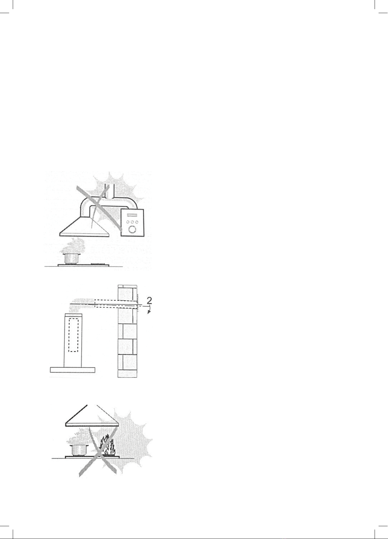
Do not connect the extractor hood to exhaust ducts carrying combustion flumes
(boilers, fireplaces, etc.).
If the extractor is used in conjunction with non-electrical appliances (e.g. gas burning
appliances),a sufficient degree of aeration must be guaranteed in the room in order to
prevent the backflow of exhaust gas. The kitchen must have an opening
communicating directly with the open air in order to guarantee the entry of clean air.
When the cooker hood is used in conjunction with appliances supplied with energy
other than electric, the negative pressure in the room must not exceed 0,04 mbar to
prevent fumes being drawn back into the room by the cooker hood.
In the event of damage to the power cable, it must be replaced by the manufacturer or
by the technical service department, in order to prevent any risks.
If the instructions for installation for the gas hob specify a greater distance specified
above, this has to be taken into account. Regulations concerning the discharge of air
have to be fulfilled.
USE
The extractor hood has been designed exclusively for domestic use to eliminate
kitchen smells.
Never use the hood for purposes other than for which it has been designed.
Never leave high naked flames under the hood when it is in operation.
Adjust the flame intensity to direct it onto the bottom of the pan only, making sure that
it does not engulf the sides.
Deep fat fryers must be continuously monitored during use: overheated oil can burst
into flames.
Do not flame under the range hood; risk of fire.
This appliance can be used by children aged from 8 years and above and persons
with reduced physical, sensory or mental capabilities or lack of experience and
knowledge if they have been given supervision or instruction concerning use of the
appliance in a safe way and understand the hazards involved.
Children should be supervised to ensure that they do not play with the appliance.
Cleaning and user maintenance shall not be made by children without supervision.
“CAUTION: Accessible parts may become hot when used with cooking appliances”.
MAINTENANCE
Switch off or unplug the appliance from the mains supply before carrying out any
maintenance work.
Clean and/or replace the Filters after the specified lime period (Fire hazard).
Clean the hood using a damp cloth and a neutral liquid detergent.
The appliance uses 4 hob elements at most.
The symbol is packaging indicates that this product may not be treated as household
waste. Instead it shall be handed over to the applicable collection point for the recycling of
electrical and electronic equipment. By ensuring this product is disposed of correctly, you
will help prevent potential negative consequences for the environment and human health,
which could otherwise be caused by inappropriate waste handling of this product. For more
detailed information about recycling of this product, please contact your local city office,
your household waste disposal service or the shop where you purchased the product.
2
RECOMMENDATIONS AND SUGGESTIONS
The instructions for Use apply to several versions of this appliance. Accordingly, you
may find descriptions of individual features that do not apply to your specific appliance.
INSTALLATION
The manufacturer will not be held liable for any damages resulting from incorrect or
improper installation.
The minimum safety distance between the cooker top and the extractor hood is 650
mm (some models can be installed at a lower height, please refer to the paragraphs
on working dimensions and installation).
Check that the mains voltage corresponds to that indicated on the rating plate fixed to
the inside of the hood.
For Class I appliances, check that the domestic power supply guarantees adequate
earthing.
Connect the extractor to the exhaust flue through a pipe of minimum diameter 120mm.
The route of the flue must be as short as possible.
Do not connect the extractor hood to exhaust ducts carrying combustion flumes
(boilers, fireplaces, etc.).
If the extractor is used in conjunction with non-electrical appliances (e.g. gas burning
appliances),a sufficient degree of aeration must be guaranteed in the room in order to
prevent the backflow of exhaust gas. The kitchen must have an opening
communicating directly with the open air in order to guarantee the entry of clean air.
When the cooker hood is used in conjunction with appliances supplied with energy
other than electric, the negative pressure in the room must not exceed 0,04 mbar to
prevent fumes being drawn back into the room by the cooker hood.
In the event of damage to the power cable, it must be replaced by the manufacturer or
by the technical service department, in order to prevent any risks.
If the instructions for installation for the gas hob specify a greater distance specified
above, this has to be taken into account. Regulations concerning the discharge of air
have to be fulfilled.
USE
The extractor hood has been designed exclusively for domestic use to eliminate
kitchen smells.
Never use the hood for purposes other than for which it has been designed.
Never leave high naked flames under the hood when it is in operation.
Adjust the flame intensity to direct it onto the bottom of the pan only, making sure that
it does not engulf the sides.
Deep fat fryers must be continuously monitored during use: overheated oil can burst
into flames.
Do not flame under the range hood; risk of fire.
This appliance can be used by children aged from 8 years and above and persons
with reduced physical, sensory or mental capabilities or lack of experience and
knowledge if they have been given supervision or instruction concerning use of the
appliance in a safe way and understand the hazards involved.
Children should be supervised to ensure that they do not play with the appliance.
Cleaning and user maintenance shall not be made by children without supervision.
“CAUTION: Accessible parts may become hot when used with cooking appliances”.
MAINTENANCE
Switch off or unplug the appliance from the mains supply before carrying out any
maintenance work.
Clean and/or replace the Filters after the specified lime period (Fire hazard).
Clean the hood using a damp cloth and a neutral liquid detergent.
The appliance uses 4 hob elements at most.
The symbol is packaging indicates that this product may not be treated as household
waste. Instead it shall be handed over to the applicable collection point for the recycling of
electrical and electronic equipment. By ensuring this product is disposed of correctly, you
will help prevent potential negative consequences for the environment and human health,
which could otherwise be caused by inappropriate waste handling of this product. For more
detailed information about recycling of this product, please contact your local city office,
your household waste disposal service or the shop where you purchased the product.
2
7
USAGE CONDITIONS AND RESTRICTIONS
• The rangehood has been designed exclusively for
domestic use to eliminate kitchen smells.
• Never use the hood for purposes other than for which it
has been designed.
• Never leave high naked flames under the hood when it
is in operation.
• Adjust the flame intensity to direct it onto the bottom
of the pan only, making sure that it does not engulf the
sides.
• Deep fat fryers must be continuously monitored during
use: overheated oil can burst into flames.
• Do not flame under the rangehood; risk of fire.
• This appliance can be used by children aged from 8
years and above and persons with reduced physical,
sensory or mental capabilities or lack of experience
and knowledge if they have been given supervision or
instruction concerning use of the appliance in a safe
way and understand the hazards involved.
• Children should be supervised to ensure that they do
not play with the appliance.
• Cleaning and user maintenance shall not be made by
children without supervision.
CAUTION: Accessible parts may become hot when used
with cooking appliances
MAINTENANCE
• If there is any fault occurred with the appliance, please
contact the Residentia Group Support Team on
1300 11 HELP (4357).
• Prior to any maintenance, cleaning operation, ensure
the power is cut off.
• If the supply cord is damaged, it must be replaced by
the manufacturer, service agent or similarly qualified
person in order to avoid a hazard.
• The replaced power cord should be provided by
manufacturer or seller.
• If the plug or cord is damaged, please contact the
Residentia Group Support Team.
• Use the unit according to the instructions to avoid any
fire hazard.
• Check that the mains voltage corresponds to that
indicated on the rating plate fixed to the inside of the
rangehood.
• Clean and/or replace the Filters after the specified time
period (Fire hazard).
• Clean the hood using a damp cloth and a neutral liquid
detergent.
• The appliance uses 4 hob elements at most
DISPOSAL
The symbol on the packaging indicates that this product
may not be treated as household waste. Instead it shall
be handed over to the applicable collection point for
the recycling of electrical and electronic equipment. By
ensuring this product is disposed of correctly, you will
help prevent potential negative consequences for the
environment and human health, which could otherwise
be caused by inappropriate waste handling of this
product. For more detailed information about recycling
of this product, please contact your local city office, your
household waste disposal service or the shop where you
purchased the product.
RECOMMENDATIONS AND SUGGESTIONS
The instructions for Use apply to several versions of this appliance. Accordingly, you
may find descriptions of individual features that do not apply to your specific appliance.
INSTALLATION
The manufacturer will not be held liable for any damages resulting from incorrect or
improper installation.
The minimum safety distance between the cooker top and the extractor hood is 650
mm (some models can be installed at a lower height, please refer to the paragraphs
on working dimensions and installation).
Check that the mains voltage corresponds to that indicated on the rating plate fixed to
the inside of the hood.
For Class I appliances, check that the domestic power supply guarantees adequate
earthing.
Connect the extractor to the exhaust flue through a pipe of minimum diameter 120mm.
The route of the flue must be as short as possible.
Do not connect the extractor hood to exhaust ducts carrying combustion flumes
(boilers, fireplaces, etc.).
If the extractor is used in conjunction with non-electrical appliances (e.g. gas burning
appliances),a sufficient degree of aeration must be guaranteed in the room in order to
prevent the backflow of exhaust gas. The kitchen must have an opening
communicating directly with the open air in order to guarantee the entry of clean air.
When the cooker hood is used in conjunction with appliances supplied with energy
other than electric, the negative pressure in the room must not exceed 0,04 mbar to
prevent fumes being drawn back into the room by the cooker hood.
In the event of damage to the power cable, it must be replaced by the manufacturer or
by the technical service department, in order to prevent any risks.
If the instructions for installation for the gas hob specify a greater distance specified
above, this has to be taken into account. Regulations concerning the discharge of air
have to be fulfilled.
USE
The extractor hood has been designed exclusively for domestic use to eliminate
kitchen smells.
Never use the hood for purposes other than for which it has been designed.
Never leave high naked flames under the hood when it is in operation.
Adjust the flame intensity to direct it onto the bottom of the pan only, making sure that
it does not engulf the sides.
Deep fat fryers must be continuously monitored during use: overheated oil can burst
into flames.
Do not flame under the range hood; risk of fire.
This appliance can be used by children aged from 8 years and above and persons
with reduced physical, sensory or mental capabilities or lack of experience and
knowledge if they have been given supervision or instruction concerning use of the
appliance in a safe way and understand the hazards involved.
Children should be supervised to ensure that they do not play with the appliance.
Cleaning and user maintenance shall not be made by children without supervision.
“CAUTION: Accessible parts may become hot when used with cooking appliances”.
MAINTENANCE
Switch off or unplug the appliance from the mains supply before carrying out any
maintenance work.
Clean and/or replace the Filters after the specified lime period (Fire hazard).
Clean the hood using a damp cloth and a neutral liquid detergent.
The appliance uses 4 hob elements at most.
The symbol is packaging indicates that this product may not be treated as household
waste. Instead it shall be handed over to the applicable collection point for the recycling of
electrical and electronic equipment. By ensuring this product is disposed of correctly, you
will help prevent potential negative consequences for the environment and human health,
which could otherwise be caused by inappropriate waste handling of this product. For more
detailed information about recycling of this product, please contact your local city office,
your household waste disposal service or the shop where you purchased the product.
2
8
Model
GGSSL60DR2S
Product dimensions (W, D, H mm)
595 × 308 × 175
Extraction
550m3/hr
Features
• 2-speed button control
• Dual motors
• 1 × 1.5W LED lamp
• 1 × 5 layer aluminium grease filter
• Stainless steel front fascia
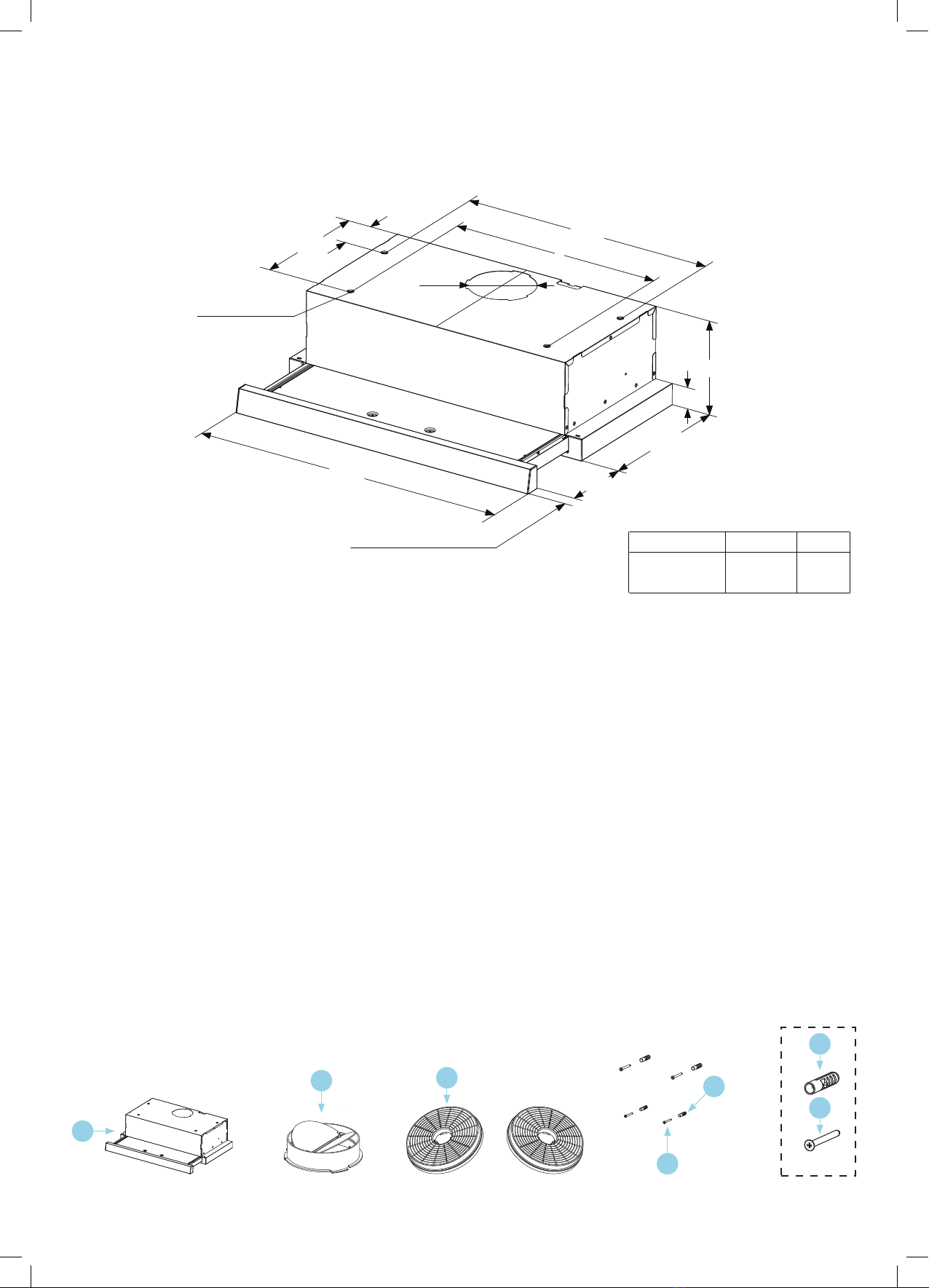
Rangehood components
1. 1 × Rangehood body
(complete with controls, light, blower & filter)
2. Check valve
3. 1 × Activated charcoal filter (Optional component)
4. 1 × Pack of screws
5. Wall plugs
Typical installation tool required
You’ll most likely require the following tools/equipment
(not supplied) for the installation of your rangehood.
• Electrical drill
• Tape measure
• Screw driver
If ducting your rangehood, you’ll also most likely require:
• Jig saw
• Ladder
• Duct-tape
• Ducting
COMPONENTS
Ref.
Qty.
Product Components
1
1
Hood Body, complete with: Controls, Light,
Blower, Filter.
2
1
Check valve
3
2
The Activated Charcoal filter (1 / 2 optional )
4
4Screws 5 x 50
5 4 Wall Plugs
1
2
3
5
4
4
5
3
COMPONENTS
Ref.
Qty.
Product Components
1
1
Hood Body, complete with: Controls, Light,
Blower, Filter.
2
1
Check valve
3
2
The Activated Charcoal filter (1 / 2 optional )
4
4Screws 5 x 50
5 4 Wall Plugs
1
2
3
5
4
4
5
3
COMPONENTS
Ref.
Qty.
Product Components
1
1
Hood Body, complete with: Controls, Light,
Blower, Filter.
2
1
Check valve
3
2
The Activated Charcoal filter (1 / 2 optional )
4
4Screws 5 x 50
5 4 Wall Plugs
1
2
3
5
4
4
5
3
COMPONENTS
Ref.
Qty.
Product Components
1
1
Hood Body, complete with: Controls, Light,
Blower, Filter.
2
1
Check valve
3
2
The Activated Charcoal filter (1 / 2 optional )
4
4Screws 5 x 50
5 4 Wall Plugs
1
2
3
5
4
4
5
3
COMPONENTS
Ref.
Qty.
Product Components
1
1
Hood Body, complete with: Controls, Light,
Blower, Filter.
2
1
Check valve
3
2
The Activated Charcoal filter (1 / 2 optional )
4
4Screws 5 x 50
5 4 Wall Plugs
1
2
3
5
4
4
5
3
Specifications & Components
DIMENSIONS
240 Y480
X
Ø118
Security hole
175
40
280
595 135
Option
XY
OPTIONAL 28/18 Double motor 423 88
5
527
Min. Min.
650
OPTIONAL 43/80
135280
175
118
unit:mm
4
DIMENSIONS
240 Y480
X
Ø118
Security hole
175
40
280
595 135
Option
X
Y
OPTIONAL 28/18
Double motor 423 88
5
527
Min. Min.
650
OPTIONAL 43/80
135280
175
118
unit:mm
4
Option
Double Motor 423 88
X Y
1
2
4
35
4
5

9
Installation Instructions
DIMENSIONS
240 Y480
X
Ø118
Security hole
175
40
280
595 135
Option
X
Y
OPTIONAL 28/18 Double motor 423 88
5
527
Min. Min.
650
OPTIONAL 43/80
135280
175
118
unit:mm
4
Electric Cooktop
Min. 650mm
Gas Cooktop
Min. 650mm
175mm
DIMENSIONS
240 Y480
X
Ø118
Security hole
175
40
280
595 135
Option
X
Y
OPTIONAL 28/18 Double motor 423 88
5
527
Min. Min.
650
OPTIONAL 43/80
135280
175
118
unit:mm
4
DIMENSIONS
240 Y480
X
Ø118
Security hole
175
40
280
595 135
Option
X
Y
OPTIONAL 28/18 Double motor 423 88
5
527
Min. Min.
650
OPTIONAL 43/80
135280
175
118
unit:mm
4
DIMENSIONS
240 Y480
X
Ø118
Security hole
175
40
280
595 135
Option
XY
OPTIONAL 28/18 Double motor 423 88
5
527
Min. Min.
650
OPTIONAL 43/80
135280
175
118
unit:mm
4
10
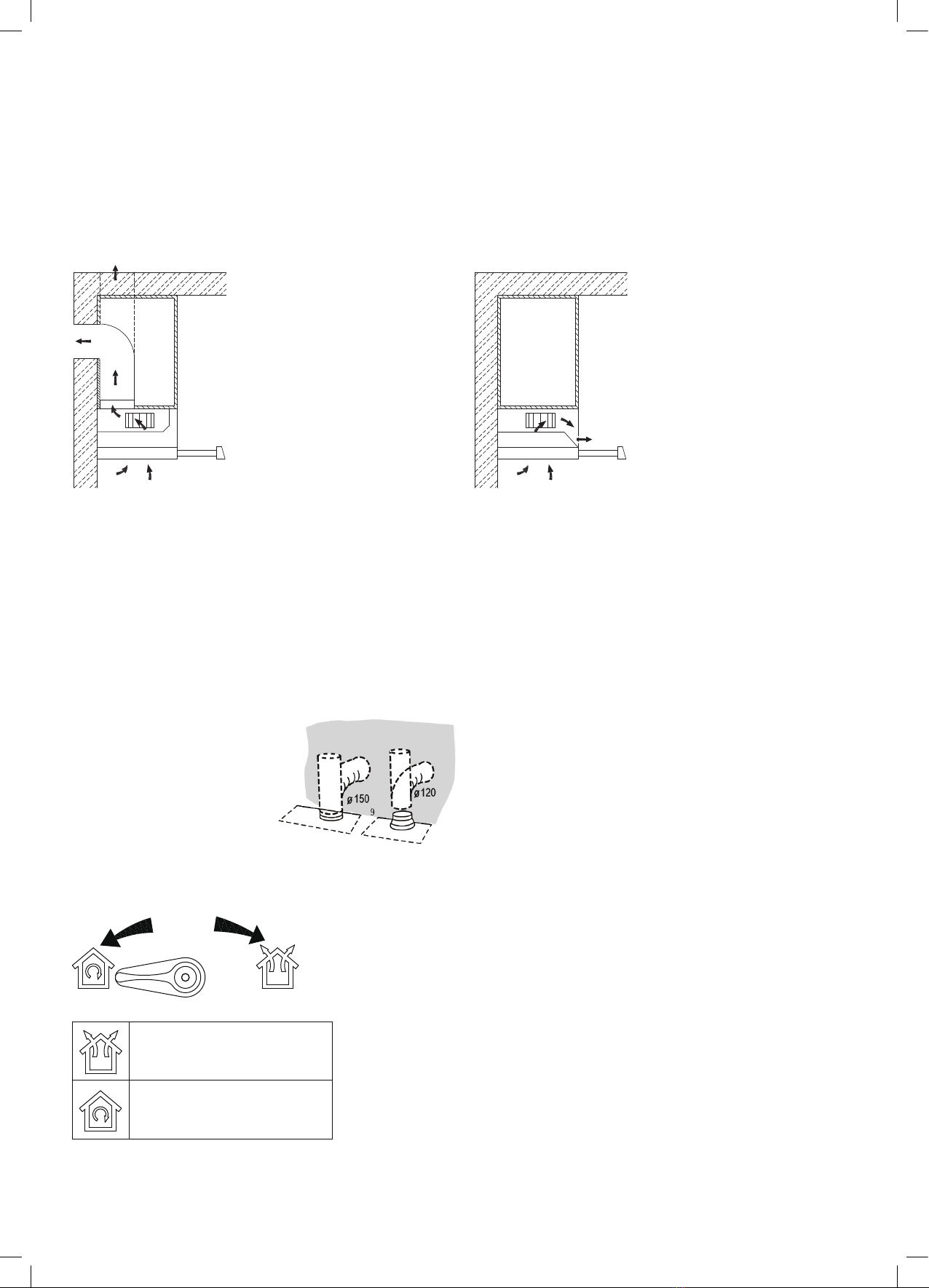
VENTILATION
Installation Instructions (continued)
Before installation, make a decision whether you want the air extracted or recirculating.
Venting knob position:
CONNECTIONS
DUCTED VERSION AIR EXHAUST SYSTEM
When installing the ducted version, connect the hood to the chimney
using either a flexible or rigid pipe ɸ 150 or ɸ 120 mm, the choice of
which is left to the installer.
To install a ɸ 120 mm air exhaust connection, insert the reducer
flange 3 on the hood body outlet.
Fix the pipe 4 in position using sufficient pipe clamps (not
supplied).
Remove possible charcoal filters.
CHOOSE A VENTING MODE
Here two venting modes, extraction-air mode and recirculation mode, before installing should
be select one of them.
Extraction-air mode, the air is discharged out of the house by a pipe.
Recirculation mode, the air is purified and discharged into the house.
Information
Recirculation mode(For single motor), the cabinet needs an air vent (For one motor optional).
Recirculation mode(For double motors), always be with activated carbon filter.
Recirculation mode, always be with activated carbon filter(s).
Recirculation mode, when activated carbon filter(s) attached, the suction power will be lowered.
Recirculation model for double motors
Extraction-air mode:
Turn the venting knob here
means venting outside
Circulating-air mode:
Turn the venting knob here
means recirculation
Venting knob position(optional)
Recirculation mode
(Double motors)
Extraction-air mode
7
Air extracted:
The air is discharged out of the house by a pipe.
(Carbon filters can be used but it will impact the
extraction power)
When installing the ducted version, connect the
rangehood to the chimney using either a flexible or rigid
pipe ɸ150 or ɸ120 mm, the choice of
which is left to the installer.
• To install a ɸ120 mm air exhaust connection, insert the
reducer flange 3on the hood body outlet.
• Fix the pipe 4in position using sufficient pipe clamps
(not supplied).
• Remove possible charcoal filters.
Recirculating:
The air is purified and discharged into the house.
(Always use activated carbon filters when recirculating)
11
METHOD #1
• The minimum safety distance between the cooker top and the rangehood is 650mm (some models can
be installed at a lower height, please refer to the paragraphs on working dimensions and installation).
• Check that the mains voltage corresponds to that indicated on the rating plate fixed to the inside of
the rangehood.
CAUTION
When cutting or drilling into wall or ceiling, do not damage electrical wiring or other hidden utilities
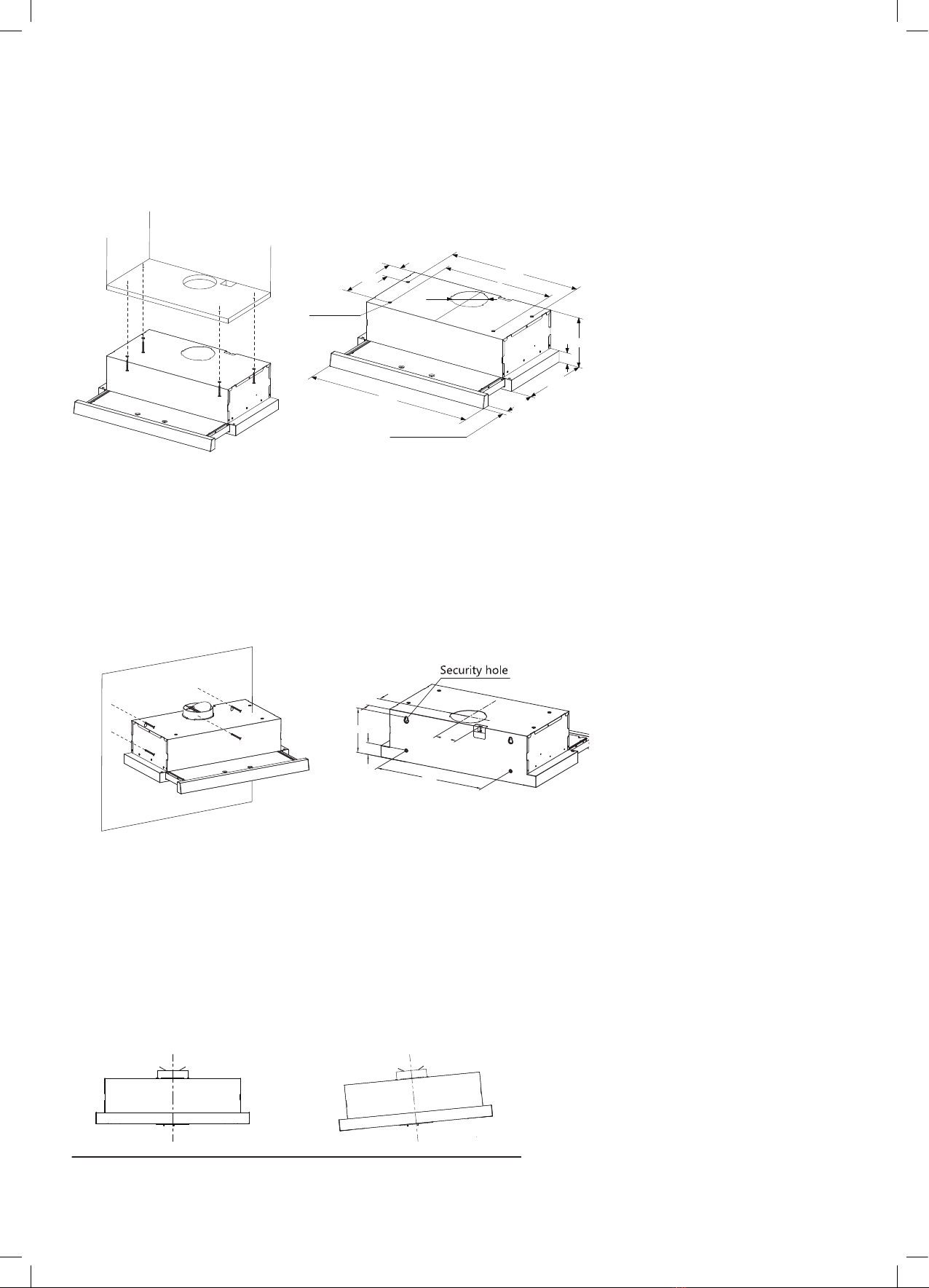
METHOD #2
• In the installation surface in cabinet don’t adapt to install the cooker hood, then as per fig, fix the position
of rangehood on the wall.
• On the wall, install 2 screws (supplied) according to the relative position of 2 key holes on the back of rangehood.
• The extent of screwing should be convenience to the next installation.
• Also install screws in the security holes, in case of front and back moving of hood, so that the using is safer.
INSTALLATION OF HOODS BUILT IN COMBI CABINETS IS THE SAME AS PREVIOUS METHOD.
CAUTION
The rangehood must not be installed and connected to flues where other appliances are installed and which run
off other energy supplied different to electricity (water heater boiled cookers (range/gas) etc.).
INSTALLATION
METHOD 1
Y480
X
Ø118
175
40
280
135
240
Security hole
595
OPTIONAL 28/18
IInnffoorrmmaattiioonn
When cutting or drilling into wall or ceiling, do not damage electrical wiring or
other hidden utilities.
METHOD 2
According to the figure, make sure the position of hood in the cabinet. The wood strips
should be line up with the 4 keyholes slots on the top of the range hood. On the cabinet,
install 4 screws (supplied) according to the relative position of 4 key holes on the bottom
of hood. The extent of screwing should be convenience to the next installation.
Hang the hood and let it’s 4 key holes aim at screws, the 4 screws should be in the
narrow parts of key holes. Screws should be fasten firmly, make sure that the installation
between the hood and cabinet is enough fasten.
Install screws in the security holes, in case of front and back moving of hood, so that
the using is safer.
69
155
40
400
Double motors
80
5
In the installation surface in cabinet don’t adapt to install the cooker hood, then as per fig, fix
the position of cooker hood on the wall.
On the wall, install 2 screws ( supplied ) according to the relative position of 2 key holes on
the back of hood.
The extent of screwing should be convenience to the next installation.
Also install screws in the security holes, in case of front and back moving of hood, so that the
using is safer.
IInnssttaallllaattiioonn ooff hhooooddss bbuuiilltt iinn ccoommbbii ccaabbiinneettss iiss tthhee ssaammee aass pprreevviioouuss mmeetthhoodd..
IInnffoorrmmaattiioonn
The cooker hood must not be installed and connected to flues where other appliances are
installed and which run off other energy supplied different to electricity(water heater boiled
cookers(range/agas)etc.).
Right Wrong
IInnffoorrmmaattiioonn
Congratulations on the purchase our cooker hood which is designed to include many superior
features that permit you the fullest expression of your living. Before installing and/or using the
cooker hood carefully read all the instruction.
6

12
Operating Your Rangehood
Checking the valve installation
Hold the check valve with your hands, align the box gap,
put in the check valve,
and then rotate until three angles of the valve are locked.
Installation is complete.
Cleaning the cooker hood:
To protect the main body of your rangehood from
corrosion or stains, the cooker hood should be cleaned
with hot water with a non-corrosive detergent every
two months. For stubborn stains or marks, you can try
using a specific stainless steel cleaner available from
most supermarkets.
Warning!
• Do not use a corrosive detergent or abrasive cloths as
they will damage the body.
• Keep the motor and mechanics free from water.
• Always switch the power off at the outlet and unplug
the rangehood before cleaning.
• If your rangehood plug or cord is damaged, please
ensure your rangehood remains unplugged and contact
After Sales Support for further assistance.
• If you’re using a carbon filter, it should never be exposed
to heat.
Cleaning and Maintenance
USE
Operation
Check beforehand
Check the safe condition of the appliance:
Check whether there are visible defects.
Check that all parts of the appliance have been securely fitted.
Switching on/off
Motor Operation
[ ]=Off
[ ]=Low Power Setting
[ ]=High Power Setting
In the right part of the cooker hood. (For some models)
There are 2 speeds for the motor and on off switch of the lamp.
Locker switch for operation.
Light Operation
[ ]=Off
[ ]=On
CHECK VALVE INSTALLATION
Hold on check valve with your hands, align the box gap, put in the check valve , and then spin
to a certain angle until three anglesof the valve are stuck. Installation is complete.
MAINTENANC
8
BEFORE FIRST USE
To ensure that the rangehood is in a safe condition:
• Check whether there are visible defects.
• Check that all parts of the appliance have been securely fitted.
OPERATION
Your Slide-out Rangehood features switch button controls with two speed levels of extraction.
Motor Operation Switch
The Low Power Setting is recommended for ventilation in standard cooking operations.
When there is a high density of smoke or steam produced, it is recommended to select
the High Power Setting for the most effective ventilation.
[ ] = Off
[ | ] = Low Power Setting
[ || ] = High Power Setting
Light Operation Switch
Select this button to turn the light on and off.
[ ] = Off
[
USE
Operation
Check beforehand
Check the safe condition of the appliance:
Check whether there are visible defects.
Check that all parts of the appliance have been securely fitted.
Switching on/off
Motor Operation
[ ]=Off
[ ]=Low Power Setting
[ ]=High Power Setting
In the right part of the cooker hood. (For some models)
There are 2 speeds for the motor and on off switch of the lamp.
Locker switch for operation.
Light Operation
[ ]=Off
[ ]=On
CHECK VALVE INSTALLATION
Hold on check valve with your hands, align the box gap, put in the check valve , and then spin
to a certain angle until three angl esof the valve are stuck. Installation is complete.
MAINTENANC
8
] = On
USE
Operation
Check beforehand
Check the safe condition of the appliance:
Check whether there are visible defects.
Check that all parts of the appliance have been securely fitted.
Switching on/off
Motor Operation
[ ]=Off
[ ]=Low Power Setting
[ ]=High Power Setting
In the right part of the cooker hood. (For some models)
There are 2 speeds for the motor and on off switch of the lamp.
Locker switch for operation.
Light Operation
[ ]=Off
[ ]=On
CHECK VALVE INSTALLATION
Hold on check valve with your hands, align the box gap, put in the check valve , and then spin
to a certain angle until three anglesof the valve are stuck. Installation is complete.
MAINTENANC
8
13
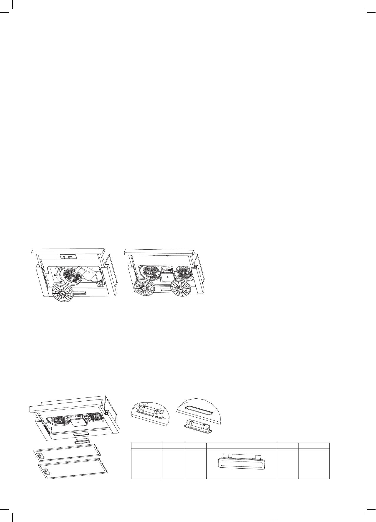
Cleaning the grease filters (recommended every two months)
Keeping this filters clean will keep the rangehood extraction performance at an optimum.
Ensure you never use a corrosive detergent during cleaning.
• The filters must be cleaned every 2 months of operation, or more frequently for particularly heavy usage
• Put the filter into 40–50°C clean water with a small amount of regular dishwashing liquid, and soak for 2–3 minutes.
Wear gloves and clean with a soft brush. They can be washed in a dishwasher.
• Pull the comfort panels to open them.
• Remove the filters one by one pushing them towards the back side of the rangehood unit and simultaneously
pulling downwards.
• Avoid applying too much pressure, as the filter is delicate and will damage easy.
• Ensure that they are completely dry before refitting them back into place.
(The colour of the filter surface may change throughout the time but this has no impact to the filter efficiency)
• When fitting the filters into the hood pay attention that they are mounted in correct position the handle
facing outwards.
• Close the comfort panel.
Changing the charcoal filter (recirculation version)
These filters are not washable and cannot be regenerated, and must be replaced approximately every 4 months of
operation, or more frequently with heavy usage.
• Remove the metal grease filters
• Remove the saturated activated charcoal filter.
• Fit the new filters.
• Replace the metal grease filters.
Light replacement
Lightning inside the appliance is provided by a 1.5W LED light.
To replace the LED light:
1. Disconnect the appliance from the mains or switch off the circuit breaker.
2. Remove the metal filters (see Cleaning the grease filters).
3. Remove the light by levering its fitting from the hood body (this may require
pressure or force to be applied) and disconnect the connector of the light.
4. Replace the light with a n ew one of the same type, making sure that you
connect the light with the light cable correctly.
5. Install the metal filter back in place.
Cleaning and Maintenance (continued)
GREASE FILTERS
CLEANING METAL SELF-SUPPORTING GREASE FILTERS
The filters must be cleaned every 2 months of operation, or
more frequently for particularly heavy usage, and can be
washed in a dishwasher.
Pull the comfort panels to open them.
Remove the filters one by one pushing them towards the back
side of the hood unit and simultaneously pulling downwards.
Any kind of bending of the filters has to be avoided when
washing them. Before fitting them again into the hood make sure
that they are completely dry. (The color of the filter surface may
change throughout the time but this has no influence to the filter
efficiency).
When fitting the filters into the hood pay attention that they are
mounted in correct position the handle facing outwards.
Close the comfort panel.
ACTIVATED CHARCOAL FILTER (RECIRCULATION VERSION)
These filters are not washable and cannot be regenerated, and must be replaced approximately
every 4 months of operation, or more frequently with heavy usage.
REPLACING THE ACTIVATED CHARCOAL FILTER
Remove the metal grease filters
Remove the saturated activated charcoal filter.
Fit the new filters.
Replace the metal grease filters.
9
DISPOSAL OF OLD ELECTRICAL APPLIANCES
The European directive 2012/19/EU on Waste Electrical and Electronic Equipment (WEEE), requires that old
household electrical appliances must not be disposed of in the normal unsorted municipal waste stream. Old
appliances must be collected separately in order to optimize the recovery and recycling of the materials they contain,
and reduce the impact on human health and the environment.
The crossed out “wheeled bin” symbol on the product reminds you of your obligation, that when you dispose of the
appliance, it must be separately collected.
Consumers should contact their local authority or retailer for information concerning the correct disposal of their old
appliance.
LIGHTING
LIGHT REPLACEMENT
1. Disconnect the appliance from the mains or switch off the circuit breaker.
2. Remove the metal filters (see Cleaning and Replacing Filters) .
3. Remove the light by levering its fitting from the hood body(this may require pressure or
force to be applied) and disconnect the connector of the light.
4. Replace the light with a n ew one of the same type, making sure that you connect the light
with the light cable correctly.
5. Install the metal filter back in place.
Changing the light
Lightning inside the appliance is provided by a 1.5W LED light.
To replace the LED light, proceed as follows:
Self-ballasted
LED modules
DBS-1.5-
H-33.2/120
Max power Voltage Picture Lamp Cap ILCOS D code
1.5W
Square/Diameter:33.2mmx120mm
/
220-240V
10

14
Troubleshooting
Operation in case of emergency
In the event of an emergency you should:
• Switch off all rangehood controls
• Switch off the rangehood off at the power outlet and immediately unplug
• Please contact the Residentia Group Support Team on 1300 11 HELP (4357).
Some minor faults can be fixed by referring to the instructions given in the table below. There is also a
self-help section online at http://www.residentiagroup.com.au
IMPORTANT!
If your appliance appears to be operating incorrectly, then you should disconnect it from your electrical supply and
then contact the Residentia Group Support team on 1300 11 HELP (4357).
WARNING!
Do not attempt to repair the rangehood yourself.
Please note that if an engineer is asked to attend whilst the product is under warranty and finds that the problem is
not the result of an appliance fault, then you may be liable for the cost of the call out charge.
The appliance must be accessible for the engineer to perform any necessary repair. If your appliance is installed in
such a way that an engineer is concerned that the damage will be caused to the appliance or your kitchen, then they
will not complete a repair. This includes situations where the rangehood has been tiled or sealed in with a sealant.
Please refer to the conditions that appear on the warranty card at the rear of this user manual.
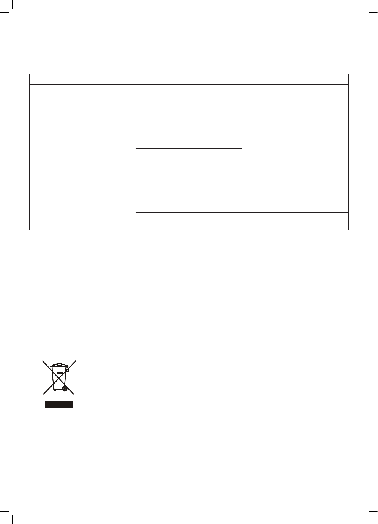
FAULT CAUSE SOLUTION
Light works but the motor does not The blades are blocked. Contact the Residentia Group
Support Team on 1300 11 HELP (4357).
The capacitor is damaged. Contact the Residentia Group
Support Team on 1300 11 HELP (4357)
to replace the capacitor.
The motor is damaged. Contact the Residentia Group
Support Team on 1300 11 HELP (4357)
to replace the motor.
The internal wiring of motor is
disconnected or damaged. An
unpleasant smell may be present.
Both light and motor do not work The internal wiring of motor is
disconnected or damaged. An
unpleasant smell may be present.
Contact the Residentia Group
Support Team on 1300 11 HELP (4357)
to replace the motor.
The light is damaged. Light will need replacing.
Power cord may be loose Contact the Residentia Group
Support Team on 1300 11 HELP (4357)
for the technician to reconnect wires
as per electric diagram.
15
DISPOSAL OF OLD ELECTRICAL APPLIANCES
The European directive 2012/19/EU on Waste Electrical and Electronic Equipment (WEEE),
requires that old household electrical appliances must not be disposed of in the normal
unsorted municipal waste stream. Old appliances must be collected separately in order to
optimize the recovery and recycling of the materials they contain, and reduce the impact
on human health and the environment.
The crossed out “wheeled bin” symbol on the product reminds you of your obligation, that
when you dispose of the appliance, it must be separately collected.
Consumers should contact their local authority or retailer for information concerning the
correct disposal of their old appliance.
FAULT CAUSE SOLUTION
There is oil leakage
Outlet and the air ventilation
entrance is not tightly sealed.
Contact the Residentia Group
Support Team on 1300 11 HELP (4357)
to send out a technician.
Leakage from the connection of
U-shaped section and cover.
Vibration Blades can cause vibration if
damaged
The motor is not tightly fastened
The rangehood is not tightly fixed
Insufficient suction The distance between the rangehood
and cooktop is too large
Either close some doors or windows
or the rangehood is installed in a not
appropriate place
Too much ventilation from open
doors or windows
The rangehood inclines The fixing screws are not tight
enough
Tighten the fixing screw and make it
horizontal.
The hanging screws screws are not
tight enough
Tighten the hanging screw and make
it horizontal.
DISPOSAL OF OLD ELECTRICAL APPLIANCES
The European directive 2012/19/EU on Waste Electrical and Electronic Equipment (WEEE), requires that old
household electrical appliances must not be disposed of in the normal unsorted municipal waste stream. Old
appliances must be collected separately in order to optimize the recovery and recycling of the materials they contain,
and reduce the impact on human health and the environment.
The crossed out “wheeled bin” symbol on the product reminds you of your obligation, that when you dispose of the
appliance, it must be separately collected.
Consumers should contact their local authority or retailer for information concerning the correct disposal of their old
appliance.
LIGHTING
LIGHT REPLACEMENT
1. Disconnect the appliance from the mains or switch off the circuit breaker.
2. Remove the metal filters (see Cleaning and Replacing Filters) .
3. Remove the light by levering its fitting from the hood body(this may require pressure or
force to be applied) and disconnect the connector of the light.
4. Replace the light with a n ew one of the same type, making sure that you connect the light
with the light cable correctly.
5. Install the metal filter back in place.
Changing the light
Lightning inside the appliance is provided by a 1.5W LED light.
To replace the LED light, proceed as follows:
Self-ballasted
LED modules
DBS-1.5-
H-33.2/120
Max power Voltage Picture Lamp Cap ILCOS D code
1.5W
Square/Diameter:33.2mmx120mm
/
220-240V
10

16
This page
is intentionally
left blank
17
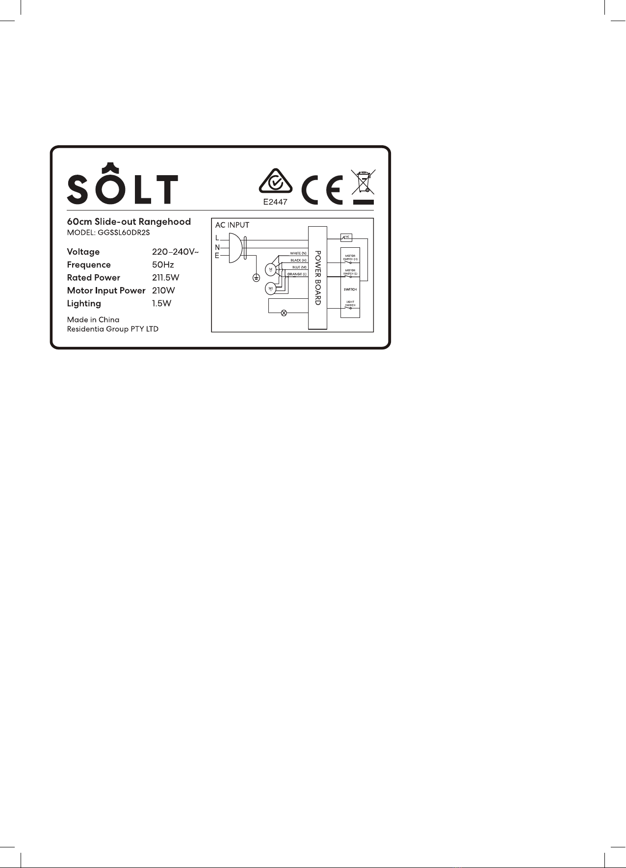
RATING PLATE
Technical Data

18
Warranty Information
WARRANTY TERMS & CONDITIONS
SLIDEOUT RANGEHOOD
This document sets out the terms and conditions of the
product warranties for Residentia Group Appliances. It is
an important document. Please keep it with your proof of
purchase documents in a safe place for future reference
should you require service for your Appliance.
1. IN THIS WARRANTY
(a) ‘acceptable quality’ as referred to in clause 10 of this
warranty has the same meaning referred to in the
ACL;
(b) ‘ACL’ means Trade Practices Amendment (Australian
Consumer Law) Act (No.2) 2010;
(c) ‘Appliance’ means any Residentia Group product
purchased by you accompanied by this document;
(d) ‘ASR’ means Residentia Group authorised service
representative;
(e) ‘Residentia Group’ means Residentia Group Pty Ltd
of 165 Barkly Ave, Burnley VIC 3121, ACN 600 546 656
in respect of Appliances purchased in Australia;
(f ) ‘major failure’ as referred to in clause 10 of this
warranty has the same meaning referred to in the
ACL and includes a situation when an Appliance
cannot be repaired or it is uneconomic for Residentia
Group, at its discretion, to repair an Appliance
during the Warranty Period;
(g) ‘Warranty Period’ means:
(i) where the Appliance is used for personal,
domestic or household use (i.e. normal
single family use) as set out in the instruction
manual, the Appliance is warranted against
manufacturing defects for 24 months, following
the date of original purchase of the Appliance;
(h) ‘you’ means the purchaser of the Appliance not
having purchased the Appliance for re-sale, and
‘your’ has a corresponding meaning.
2. This warranty only applies to Appliances purchased
and used in Australia and is in addition to (and does
not exclude, restrict, or modify in any way) any
non-excludable statutory warranties in Australia.
3. During the Warranty Period Residentia Group or
its ASR will, at no extra charge if your Appliance
is readily accessible for service, without special
equipment and subject to these terms and
conditions, repair or replace any parts which it
considers to be defective. Residentia Group or its
ASR may use remanufactured parts to repair your
Appliance. You agree that any replaced Appliances
or parts become the property of Residentia Group.
This warranty does not apply to light globes,
batteries, filters or similar perishable parts.
4. Parts and Appliances not supplied by Residentia
Group are not covered by this warranty.

19
Our goods come with guarantees that cannot be excluded under the Australian Consumer Law.
You are entitled to a replacement or refund for a major failure and for compensation for any
other reasonably foreseeable loss or damage. You are also entitled to have the goods repaired
or replaced if the goods fail to be of acceptable quality and the failure does not amount to a
major failure.
The Australian Consumer Law requires
the inclusion of the following statement
with this warranty:
5. You will bear the cost of transportation, travel and
delivery of the Appliance to and from Residentia
Group or its ASR. If you reside outside of the service
area, you will bear the cost of:
(a) travel of an authorised representative;
(b) transportation and delivery of the Appliance to and
from Residentia Group or its ASR, in all instances,
unless the Appliance is transported by Residentia
Group or its ASR, the Appliance is transported at
the owner’s cost and risk while in transit to and from
Residentia Group or its ASR.
6. Proof of purchase is required before you can make a
claim under this warranty.
7. You may not make a claim under this warranty
unless the defect claimed is due to faulty or
defective parts or workmanship. Residentia Group is
not liable in the following situations (which are not
exhaustive):
(a) the Appliance is damaged by:
(i) accident
(ii) misuse or abuse, including failure to properly
maintain or service
(iii) normal wear and tear
(iv) power surges, electrical storm damage or
incorrect power supply
(v) incomplete or improper installation
(vi) incorrect, improper or inappropriate operation
(vii) insect or vermin infestation
(viii) failure to comply with any additional
instructions supplied with the Appliance;
(b) the Appliance is modified without authority from
Residentia Group in writing;
(c) the Appliance’s serial number or warranty seal has
been removed or defaced;
(d) the Appliance was serviced or repaired by anyone
other than Residentia Group, an authorised repairer
or ASR.
8. This warranty, the contract to which it relates and
the relationship between you and Residentia Group
are governed by the law applicable where the
Appliance was purchased.
9. To the extent permitted by law, Residentia Group
excludes all warranties and liabilities (other than as
contained in this document) including liability for
any loss or damage whether direct or indirect arising
from your purchase, use or non use of the Appliance.
10. For Appliances and services provided by Residentia
Group in Australia, the Appliances come with a
guarantee by Residentia Group that cannot be
excluded under the Australian Consumer Law.
You are entitled to a replacement or refund for a
major failure and for compensation for any other
reasonably foreseeable loss or damage. You are
also entitled to have the Appliance repaired or
replaced if the Appliance fails to be of acceptable
quality and the failure does not amount to a major
failure. The benefits to you given by this warranty
are in addition to your other rights and remedies
under a law in relation to the Appliances or services
to which the warranty relates.
11. At all times during the Warranty Period, Residentia
Group shall, at its discretion, determine whether
repair, replacement or refund will apply if an
Appliance has a valid warranty claim applicable to
it.
12. To enquire about claiming under this warranty,
please follow these steps:
(a) carefully check the operating instructions, user
manual and the terms of this warranty;
(b) have the model and serial number of the Appliance
available;
(c) have the proof of purchase (e.g. an invoice)
available;
(d) telephone the numbers shown below.
13. You accept that if you make a warranty claim,
Residentia Group and its ASR may exchange
information in relation to you to enable Residentia
Group to meet its obligations under this warranty.
IMPORTANT
Before calling for service, please ensure that the steps in
point 12 have been followed.
Telephone contacts
►Service: Please call 1300 11 HELP (4357)

T. 1300 11 4357
E. support@residentiagroup.com.au
E S S E N T I A L S FOR LIFE
An initiative by
Residentia Group
www.solt.house
Table of contents
Other Solt Ventilation Hood manuals

Solt
Solt GGSRUM520S User manual

Solt
Solt GGSRCB900BS User manual

Solt
Solt GGSRUM520B User manual

Solt
Solt GGSRC600S User manual

Solt
Solt GGSRHF600W User manual

Solt
Solt GGSRIH600W User manual

Solt
Solt GGSRUM520S User manual

Solt
Solt GGSSL600S User manual

Solt
Solt GGSRC60 User manual

Solt
Solt GGSRCB900BS User manual

Solt
Solt GGSRUM900S User manual

Solt
Solt GGSRGF90S User manual

Solt
Solt GGSSL900S User manual

Solt
Solt GGSRIH600W User manual

Solt
Solt GGSRUM520B User manual

Solt
Solt GGSRCG900S User manual

Solt
Solt GGSSL60DRS User manual

Solt
Solt GGSRHF600W User manual

Solt
Solt GGSSL600S User manual

Solt
Solt GGSUM52 User manual


