SolutionAir VENTUS 450+ User manual

Version 1.2
© Solutionair 2020
VENTUS 450+
Advanced Controlled Ventilation
Owner’s Manual

VENTUS 450+ Manual
© Solutionair 2020 2 of 15
Contents
1 Welcome ....................................................................................................................................... 3
1.1 Definitions ..................................................................................................................................... 3
1.2 Overview of your System ........................................................................................................... 4
2 System Environment Requirements ............................................................................................. 5
2.1 Installation, modification, repair ............................................................................................... 5
2.2 Operating conditions ................................................................................................................. 5
2.3 Vents ............................................................................................................................................. 5
2.4 HD-Display Controller environment .......................................................................................... 5
2.5 VENTUS 450+ environment ......................................................................................................... 5
2.6 Ductwork ...................................................................................................................................... 5
2.7 Electric .......................................................................................................................................... 6
3 HD-Display Controller ................................................................................................................... 6
3.1 24-hour Graph ............................................................................................................................. 6
3.2 Settings Menu .............................................................................................................................. 7
3.3 Filter Setting .................................................................................................................................. 7
3.4 Operating Mode ......................................................................................................................... 8
4 Right amount of ventilation ......................................................................................................... 8
5 Care and Maintenance .............................................................................................................. 9
5.1 Maintenance requirements ....................................................................................................... 9
5.2 Air-Filters ....................................................................................................................................... 9
5.3 How to Change the Air-Filters.................................................................................................. 10
5.4 How to clean the Vents ........................................................................................................... 10
5.5 Use of air freshener and fragrances ....................................................................................... 10
6 Warranty Conditions ................................................................................................................... 11
6.1 Warranty in respect of the product and its installation ........................................................ 11
6.2 Warranty register ....................................................................................................................... 11
6.3 Warranty claim procedure ...................................................................................................... 11
6.4 Exclusions ................................................................................................................................... 11
6.5 Return of parts ........................................................................................................................... 12
6.6 Liability for breach of warranty ............................................................................................... 12
7 Disposal and recycling ............................................................................................................... 12
8 Technical Details ......................................................................................................................... 13
8.1 Components of your System ................................................................................................... 13
8.2 Dimensions of the VENTUS 450+ .............................................................................................. 13
8.3 Technical Parameters and Weight ......................................................................................... 13
9 Glossary ........................................................................................................................................ 14
ATTACHMENT A - Warranty Registration Form 15
VENTUS 450+ Manual
© Solutionair 2020 3 of 15
1 Welcome
Congratulations – you are the owner of the VENTUS 450+ home ventilation
solution which provides fresh air and a healthy indoor environment for you and
your family.
1.1 Definitions
Words with specific meanings are listed in a glossary at the end of this
document.
These words are capitalised and bold when used for the first time.
The following precautions will be presented in different sections of the
document:
Danger!!!
This could lead to injury or could even be lethal!!!
Warning!!
There may be a negative consequence if you don’t heed this!!
Advice!
You’ll get the best result if you follow this advice!

VENTUS 450+ Manual
© Solutionair 2020 4 of 15
1.2 Overview of your System
The VENTUS 450+ is a Home Ventilation System with Heat-Exchanger and Summer Bypass.
Ventilation is achieved by two identical variable-speed fans, one to introduce fresh air into the
house (supply air fan), and the other to extract stale air out of the house (extract air fan). The
two fans provide balanced ventilation of approximately one air change every 2 hours (based
on an average 4-bedroom house. The incoming and outgoing air flows do not mix within the
VENTUS 450+ Unit, but pass in opposite directions through a heat exchanger, so that exiting
warmer air gives up most of its heat energy to the incoming fresh air. The Summer Bypass
function activates automatically or can be activated manually during summer to introduce
cooler air into the house without passing through the heat exchanger.
Fresh air is supplied into the house through insulated Ducting and Side-Entry-Boxes for an even
airflow to vents in each room and stale return air exits via vents usually located in hallways or
other central places of the house.
In automatic mode the System is intelligent and able to sense the need to increase airflow when
necessary by constantly monitoring the internal air quality by measuring CO2 and PM2.5 levels.
The System has Air-Filters to remove impurities in the air and bring clean air into the house and
also to protect the Heat-Exchanger from contamination.
Features of the System
Efficient German EC-fans with brushless motors
Heat-Exchanger core from Recair – world leading supplier
System meets Clause G4 of the NZ Building Code for fresh air ventilation
Incoming Air-Filter rated to PM 2.5
High-rated insulated Ducting with Side-Entry-Boxes for efficient and even air distribution
CO2 and PM2.5 sensors
HD-Display Controller
4 operating modes (Auto, Energy-Saving, Haze, Bypass)
3 fan speed settings
Weekly timer
Air-Filter warning
Wi-Fi capability (currently for maintenance only)
Benefits of the System
Constant supply of fresh air produces a drier and healthier home
Constant extraction of moist stale air from the house
Occupants susceptible to respiratory illness will have a safer living environment
EC fans are very efficient resulting in low power consumption
No need to open the windows to vent the house
No need for window fly-screens as opening windows for ventilation is not required
Less dust in the house due to filtered air
Fewer insects within the house due to closed windows
Increased security due to reduced risk of (a forgotten) open window
Controlled ventilation also during absence e.g. when on holiday
Pre-warmed fresh air supply due to heat exchanger technology
Summer Heat-Exchanger bypass option for cooling the house with fresh air from outside
(No need to leave windows open during hot summer nights)
Side-Entry-Boxes deliver a more even airflow through the air supply vents

VENTUS 450+ Manual
© Solutionair 2020 5 of 15
2 System Environment Requirements
Please read the following advice and recommendations carefully.
To follow them is essential to keep you safe and ensure performance and a long
lifetime for your System.
2.1 Installation, modification, repair
Installation, modification or repair must only be performed by a Solutionair authorised Service
Technician.
2.2 Operating conditions
The VENTUS 450+ is designed to operate in most of New Zealand’s weather conditions. However,
if the conditions are outside the below stated operating range, we recommend to switch off the
System until the weather stabilises back to within the parameters.
Operating range: Outdoor Temperature -25°C to +40°C
Humidity 0% to 100% RH
Sea spray can affect the lifetime of the System and void its warranty. We do not recommend to
use the System in houses which are exposed to sea spray or similar corroding substances like high
sulphur atmosphere environments.
2.3 Vents
All Vents (outlets and exhaust vents, inside and outside of the house) must be clear of any
obstacles within 500mm around the opening.
2.4 HD-Display Controller environment
We recommend to wall-mount the HD-Display Controller in a central place of your house, e.g.
the hall way. To ensure good readability and a long lifetime of the HD-Display Controller, it
should not be exposed to direct sunlight.
Ensure that the environment of the HD-Display Controller is dry and not below 0°C and not
above 45° C.
If you need to clean the HD-Display Controller unit, use a clean damp micro fleece. Do not use
cleaning products.
2.5 VENTUS 450+ environment
The VENTUS 450+ is designed to be installed in your roof space. The environment must be dry and
not below -25°C and not above 80° C.
Do not place any items or loads on top of the VENTUS 450+ Unit. Keep the unit and its
connections free of any other obstacles.
2.6 Ductwork
The Ductwork (which includes Ducting, Plenum and Side-Entry-Boxes) is carefully installed to
ensure the best performance for your System. Do not modify the installation. If you require any
modification, please contact our Service Centre.
Do not place any items or loads on top of the Ductwork. Keep the Ductwork and its connections
free of any obstacles. Bends or kinks can cause loss of performance or may damage the VENTUS
450+ Unit.

VENTUS 450+ Manual
© Solutionair 2020 6 of 15
2.7 Electric
Be careful around all electric cables incorporated in the System! Do not perform any
modification!
If you damage a cable by accident, immediately switch off the main power supply and contact
our Service Centre.
The VENTUS 450+ Unit is plugged into a standard 230V socket and can be unplugged if needed.
Make sure you turn off the System at your HD-Display Controller first.
Note: After a power blackout the System stays on stand-by for reasons of safety until you restart it
on your HD-Display Controller.
3 HD-Display Controller
The System is turned on by touching the on/off button in the middle of the HD-Display Controller
screen. Once on, the screen displays the Home Screen:
3.1 24-hour Graph
Tap anywhere within the light blue field to see the 24 hour record of PM2.5 and CO2.
Switch between PM2.5 and CO2 graph by taping the buttons on the right.
PM2.5 sensor - This measures particulate matter (PM) which is smaller than 2.5µm (like dust or smog)
in µg per m³. The PM level is an indicator of the amount of ‘dirt’ in the air.
CO2 sensor - This measures carbon dioxide molecules in parts per million. CO2 rises when people
use air over a period of time. Fresh air contains less CO2 and more oxygen.
VENTUS 450+ Manual
© Solutionair 2020 7 of 15
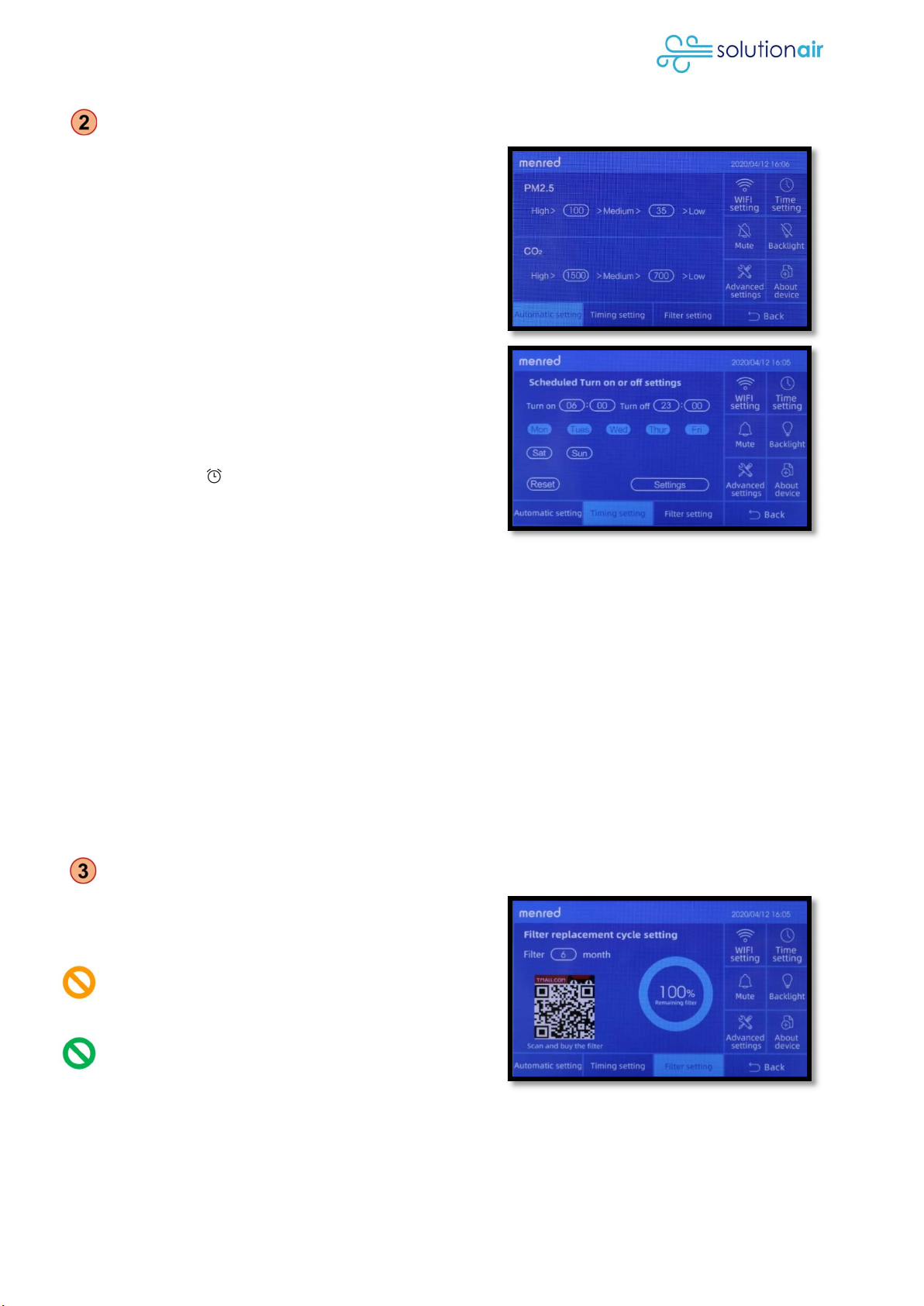
3.2 Settings Menu
Tap ‘Settings’ to see the ‘Automatic setting’ menu.
Here you can define the fan speed level
depending on the PM2.5 and CO2 sensor readings.
Tap a circled value to change it.
Below you can reach the ‘Time Setting’ and ‘Filter
Setting’. The Filter Setting can also be reached
directly from your Home Screen (see ④Filter).
Tap ‘Timing setting’ to schedule on/off times of the
unit. Tap and select single or multiple days, then tap
the circled time-values to adjust the on and off
time. After your changes, tap ‘Settings’ to save your
changes and ‘Setting Success’ will be displayed.
The ‘Reset’ button, sets the Timer back to factory
setting. To activate the timer, go back to the Home
Screen and tab ‘Timing’ to activate the timer. A
clock symbol ( ) on top of the screen indicates,
that the timer is active.
On the right side you find further setting as listed
below:
Wi-Fi Setting
Connects your System to Wi-Fi. Currently this function is not available in New Zealand.
Time Setting
Adjust time and date.
Mute
Switch beep touch noise on or off.
Backlight
Switch constant backlight on or off. Screen backlight switches off after 10 sec when disabled.
Advanced Settings
Service Settings for Service Technicians. (Code required)
About device
Basic information about the System including unique serial code.
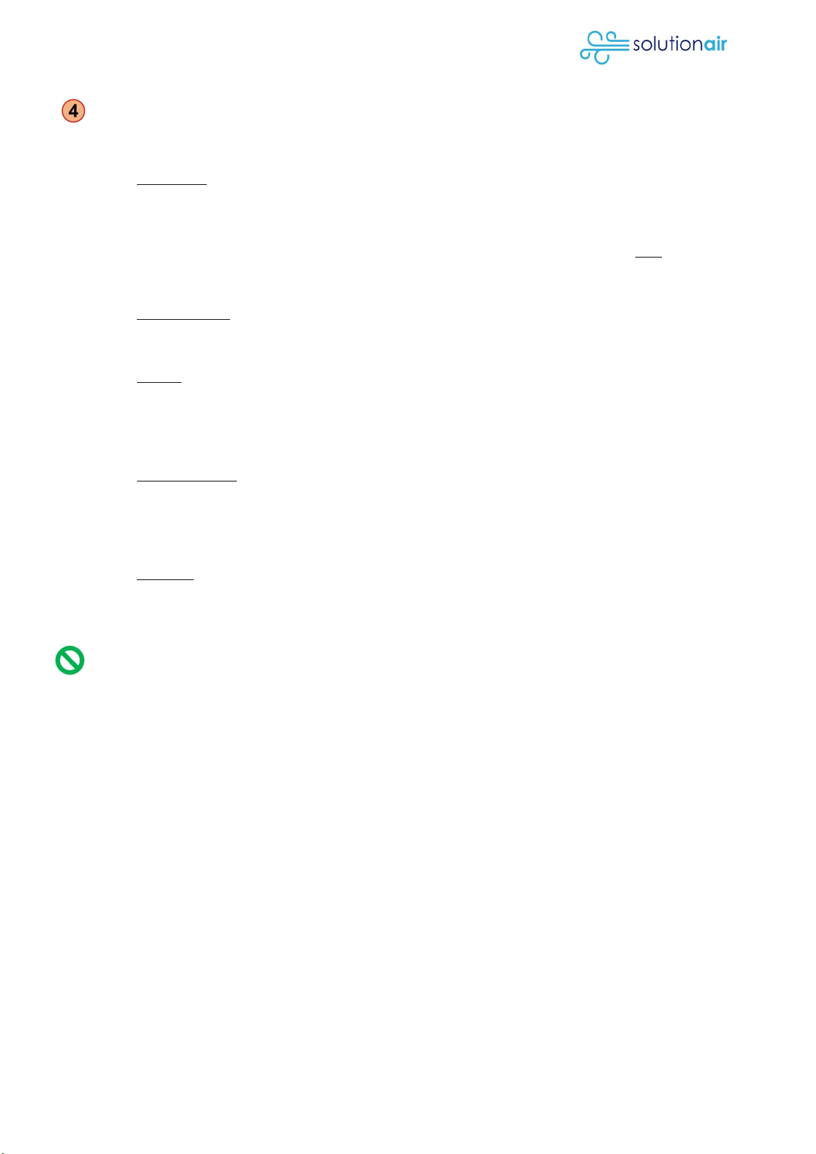
3.3 Filter Setting
Tap ‘Filter’ to see the ‘Filter setting’ menu. Here you
can see the status of your filter in percentage
based on time.
If you change the filter by your own, then you have
to enter again the ‘Filter replacement cycle setting’
of six months to reset the status.
Depending on the filter contamination level you
may want to increase or decrease the months set
for the replacement cycle.
VENTUS 450+ Manual
© Solutionair 2020 8 of 15
3.4 Operating Mode
The System has five operating modes to choose from. By tapping on the current mode symbol, you
can skip through the different modes:
Automatic The Automatic mode sets the fan speed automatically in accordance
with the setting under ‘Automatic Setting’ for CO2 and PM2.5 level
(see ②Setting Menu).
The Heat-Exchanger is engaged and only bypassed when the indoor
temperature is higher than the outdoor temperature and the outdoor
temperature higher than 20°C. When the Heat Exchanger is
bypassed, no heat or cool transfer takes place.
Energy Saving On Energy-Saving mode the Heat-Exchanger is permanently
engaged to help to retain heat or coolness inside of your house. In this
mode you can select the fan speed manually.
Bypass On Bypass mode the Heat-Exchanger is permanently disengaged by
bypassing the incoming air to help you to cool your house with cooler
air from outside, for example during summer nights. When the Heat
Exchanger is bypassed, no heat or cool transfer takes place. In this
mode you can select the fan speed manually.
Haze removing The Haze removing option allows stale air (or also warm air) to be
removed from the house quickly. The Supply Air fan will run at full
speed and the extract fan at a lower speed. For example, if you burnt
the toast and wanted the air out of the house quickly, select Haze
Removing and open a couple of windows.
Sleeping On Sleeping mode the unit reduces the noise to a minimum and sets
all fans to low speed.
4 Right amount of ventilation
Residential ventilation is governed by Clause G4 of the Building Code for fresh air ventilation. The
objective of this provision is to safeguard people from illness or loss of amenity due to lack of
fresh air. It states that:
spaces within buildings shall be provided with adequate ventilation consistent with their
maximum occupancy and their intended use, and that
spaces within buildings shall have means of ventilation with outdoor air that will provide
an adequate number of air changes to maintain air purity setting out the provisions for
outdoor air and extract ventilation.
The Building Code recommends 0.35 air changes per hour to meet the provision of clause G4.
Our findings have shown that 0.35 air changes per hour is the bare minimum air volume to keep
a home healthy and that the number of people occupying the home is a key factor in setting air
volumes.
Therefore, the air flow settings of each unit are dependent on its installation and occupancy of
the home. Settings are inputted by the installation technician based on specific calculations
that take into consideration a variety of factors.

VENTUS 450+ Manual
© Solutionair 2020 9 of 15
5 Care and Maintenance
5.1 Maintenance requirements
If the VENTUS 450+ is not working, do not attempt to open it.
The System must only be serviced by an authorised Service Technician.
The VENTUS 450+ is designed to run continuously without the need to service the fans or heat
exchanger core, provided the filters are changed regularly. However, to gain the best
performance and System longevity, the following basic maintenance work should be performed
periodically, as described below.
DIY
Authorised
Service
Technician
Minimal
interval Instructions
Check Air-Filter Yes Yes 3 months See paragraph 5.3 How to change the Filters
Change Air-
Filter Yes Yes 6 months See paragraph 5.3 How to change the Filters
Clean all inlet
(sucking) Vents Yes Yes 6 months See paragraph 5.4 How to clean the Vents
Clean all outlet
(blowing) Vents
Yes Yes 12 months See paragraph 5.4 How to clean the Vents
Inspection No Yes 24 months
We recommend a visual and data inspection
of your VENTUS 450+ by one of our authorised
Service Technicians.
Consider a shorter interval if you live close to construction site, motorway, inner city or
experience dusty air in general.
To book an appointment with one of our authorised Service Technician, please send us an email
or call us:
Solutionair Customer Service Contact
Email: enquiries@solutionair.co.nz
Phone: 0800 484 3269
5.2 Air-Filters
The VENTUS 450+ Air-Filters are designed to be changed by the owner without the expense of a
visit by a Service Technician. However, if you need assistance, please contact us and book a
Service Technician.
The Air-Filters must be changed at least every 12 months to protect fans and the heat
exchanger from damage and to meet the Warranty Terms and Conditions.
Many Air-Filters may need to be changed more regularly than every 12 months to maintain
optimum airflow and air quality. We recommend to periodically check the Air-Filters every 3
months in the first 1-2 years of using your System. By periodically inspecting the contamination
level of your Air-Filters, which heavily depends on your surrounding environment, you can
determine the ideal time frame of Air-Filter use. You can then set this time frame under ‘Filter-
Setting’ on your HD-Display Controller to remind you of the next Air-Filter change (see 3. HD-
Display Controller -> ③Filter Setting).

VENTUS 450+ Manual
© Solutionair 2020 10 of 15
5.3 How to Change the Air-Filters
Always power off the Ventus 450+ with the HD-Display Controller and
switch off the main power before opening the Ventus 450+ Unit!
At the bottom of the front panel of the Ventus 450+ Unit release the two
latches and open the access hatch.
The VENTUS 450+ Unit has an outdoor side (on the left) and an indoor
side (on the right.)
The filter on the outdoor side (left) is an H13 ‘High Efficiency Filter’.
Filter part number: V450-H13
The filter on the indoor side (right) is a G4 ‘Coarse Filter’.
Filter part number: V450-G4
To extract the filters, smoothly withdraw each filter. Each side has two
filters, joined together by tapes so the first filter will draw out the second
filter.
If any debris dislodges from the filter, wipe it out using a clean cloth.
Carefully replace the new filter, taking care that the padding does not
catch as it goes in.
Repeat the process for the filters on the opposite side.
Both filters look similar but they are not the same. If in doubt, check the
label to identify the filters.
If you take out the filters to inspect them, check the label on the filters
and make sure that they go back in the same way.
5.4 How to clean the Vents
The Vent guard can be easily removed by pushing one side of the Vent guard
and turn it 90 degree in its housing to a vertical position. Then gently pull the
Vent guard out of its housing. You may want to hold with your other hand the
housing in place. Put it back in the same way.
For cleaning the Vent guard and housing use just warm water or ph-neutral soap and a clean
cloth. Do not wash the vents in your dishwasher or use harsh cleaning products.
We recommend to clean the Fresh-Air Vent outside every three months, all Air-Extract Vents
every six months and all Air-Supply Vents and the Exhaust-Vent outside every twelve months.
5.5 Use of air freshener and fragrances
You can use your Vents for air freshening liquids and fragrances. Put a few
drops of the liquid on a little cotton ball and place it in the round
indentation in the middle of the vent guard. Only use small amounts of
liquid as oils and alcohols may damage the plastic of the Vent. Never
place liquids directly onto the plastic.
Latches
H13 Filter
G3 Filter
Heat
Exchanger

VENTUS 450+ Manual
© Solutionair 2020 11 of 15
6 Warranty Conditions
6.1 Warranty in respect of the product and its installation
Solutionair warrants to the registered Buyer that for a period of five years from the installation
date of the relevant Ventus 450+:
a) the Installation (including work performed by Solutionair’s subcontractors) was carried
out with due care and skill and that it will be reasonably fit for intended purpose, and
b) the Home Ventilation System will be free from defects due to faulty manufacturing or
workmanship by Solutionair or by Solutionair’s subcontractors.
6.2 Warranty register
In order to claim any warranty, the Buyer must register the Ventus 450+ within the first three
months after installation on the Solutionair website or by sending an email to
enquiries@solutionair.co.nz with following details:
Full name
Installation date
Address of the installation
Contact details for potential re-calls or updates
Serial code of the Ventus 450+ (see paragraph 3.3 ‘About device’)
A registration form can be found under Attachment A of this manual.
Solutionair will promptly confirm the warranty registration.
6.3 Warranty claim procedure
Any warranty claim by the Buyer must be promptly notified in writing to Solutionair (and in any
event within 30 days of the date the Buyer first becomes aware that the Home Ventilation
System is properly the subject of a claim under this term). The warranty claim notice must
provide sufficient details to enable the particular Home Ventilation System to be identified and
describing the nature and extent of the defect.
Solutionair will, within 30 work days, after receipt of a notice issued pursuant to clause 6.1,
evaluate the warranty claim.
If Solutionair determines that the warranty claim is valid, then Solutionair will, at its sole discretion
and within a reasonable time, do one or more of the following things (subject to clauses 6.3 and
6.5):
a) supply (or cause to be supplied) at Solutionair’s expense, labour and material to correct
the defect;
b) pay the Buyer a reasonable amount (comparable to HVAC industry standards) to
enable the Buyer to have the defect corrected; or
c) arrange for a third-party maintenance organisation to correct the defect at Solutionair's
reasonable cost.
6.4 Exclusions
Liability of Solutionair under any of clauses 6.1 or 6.2 will only arise in respect of the relevant
Home Ventilation System if:
a) the Buyer has exercised all due care to ensure the Home Ventilation System has, and all
parts of the Home Ventilation System have, been used in an appropriate manner to
ensure protection from damage; and
b) the Home Ventilation System has been operated and maintained by the Buyer in
accordance with this document (the “Owner’s Manual”)

VENTUS 450+ Manual
© Solutionair 2020 12 of 15
c) the Buyer has not attempted to correct the relevant defect and has not instructed or
allowed any third-party to do so without prior approval of Solutionair; and
d) the Home Ventilation System was used only in normal operating conditions, has not been
misused and has not subsequently been operated, repaired, maintained or serviced by
any person or entity other than Solutionair or one of its authorised Service Technicians,
e) the ducting or its components hasn’t been shifted or disturbed.
Except as expressly provided in clauses 6.1, 6.2, all terms, conditions, warranties, undertakings,
inducements and representations whether express or implied, statutory or otherwise relating in
any way to any goods or services supplied by or on behalf of Solutionair are hereby excluded.
6.5 Return of parts
Where possible and requested by Solutionair, the Customer must promptly return any defective
parts or components that require repair or replacement under this warranty to Solutionair and
such items will, upon receipt by Solutionair, become the property of Solutionair.
Where Solutionair requests the Buyer to return parts of the Home Ventilation System to any
particular facility for the purpose of processing a warranty claim by the Buyer, all transport
expenses (and transport insurance expenses) will be paid by the Buyer. Solutionair will reimburse
this amount (to a reasonable level, subject to clause 6.5) if, but not otherwise, Solutionair
determines that the part was properly the subject of a claim by the Buyer under clauses 6.1 or
6.2. On completion of a warranty repair, all reasonable transport expenses incurred in returning
part to the Buyer will be paid by Solutionair (subject to clause 6.5).
6.6 Liability for breach of warranty
a) Limitation of liability
Solutionair's total liability arising in connection with the Home Ventilation System and its
installation whether in tort (including for negligence or breach of statutory duty),
contract or otherwise shall not exceed the amounts actually paid by the Buyer to
Solutionair in respect of the installed Home Ventilation System.
b) Indirect and consequential loss and damage
Solutionair will not under any circumstances be liable whether in tort (including for
negligence or breach of statutory duty), contract or otherwise for any:
i. indirect or consequential loss or damage however caused;
ii. any amount in respect of any loss of use of the Home Ventilation System (or of
any part of it).
7 Disposal and recycling
When disposing of this System, follow local rules and regulations.
Most of the packaging materials are recyclable and can be reused.
Do not dispose recyclable materials in household waste.

VENTUS 450+ Manual
© Solutionair 2020 13 of 15
8 Technical Details
8.1 Components of your System
Below is a list of all main components of your Ventilation System.
Ventilation System
VENTUS 450+
o 2 EC (brushless) forward curved centrifugal fans
o High-efficiency filter set on fresh air side
o Coarse filter set on return air side
o Heat recovery core
o Summer Bypass module
o Internal motherboard
o Drain for condensation
Electric Components (wired to VENTUS 450+)
o Wall-mounted control panel
o Wall-mounted relative humidity (RH) and carbon dioxide (CO2) Sensor
Ductwork
o Up to 8 Side-Entry-Boxes and its Supply-Vents for supplying air
o Up to 2 air distribution Plenums
o Up to 4 Extract-Vents for extracting air in the house
o 1 outside Fresh-Air Vent for fresh air supply
o 1 outside Exhaust-Vent for the disposal of extracted air
8.2 Dimensions of the VENTUS 450+
VENTUS 450+Outline Dimensions
A B C D E F H
930 1105 320 150 755 1110 805
Notes
The power cable and plug is 1.5m long and suitable for Australia and New Zealand.
When viewed from the access hatch end, the spigots for outdoor air are on the left and
indoor air on the right side.
8.3 Technical Parameters and Weight
Model Voltage
(V/Hz)
Maximum
Air Volume
(m3/h)
Rated Air
Volume
(m3/h)
Rated
Power (W)
Rated
Noise
Level (dB
(A))
Weight
(Kg)
VENTUS
450+
220/50 450 350 120 42 52

VENTUS 450+ Manual
© Solutionair 2020 14 of 15
9 Glossary
VENTUS 450+ or the System means the whole ventilation system with all its components.
VENTUS 450+ Unit means the mechanical and main unit of the Ventus 450+.
Buyer means the home owner who purchased the VENTUS 450+.
CO2 means Carbon dioxide. Over time used air will show a decrease in oxygen and an
increase in CO2 which is an indicator for poor air quality.
Ducting means the insulated ducting in the roof cavity.
Ductwork means the whole duct installation including any Plenum, Side-Entry-Boxes and vents.
HD-Display Controller means the touch screen located in a central place
inside the house to control the VENTUS 450+.
Heat-Exchanger means the unit within the VENTUS 450+ Unit, which can
recover most of the heat from outgoing air and transfer it to the ingoing
air without mixing them. Same principle applies for cool air.
Home Screen means the main page of the HD-Display Controller which shows up after
switching on the System.
Home Ventilation System means a mechanical ventilation system for residential homes.
Plenum means an air distribution box which distributes the supply air to all
6 (or 8) vents. The benefit of a plenum compared to a simple Y-splitter is a
better pressure and velocity distribution over all vents.
PM2.5 means particulate matter or atmospheric aerosol particles with a diameter of 2.5μm or
less, which is about 3% the diameter of a human hair.
Service Centre means the Solutionair Customer Service.
Email: enquiries@solutionair.co.nz - Phone: 0800 484 3269
Service Technician means the service technician of Solutionair and its partners.
Side-Entry-Box means a rectangular box sitting above the Air-Supply Vents in the
roof cavity to even the airflow into the house.
Solutionair is a division of Gecko International, a 100% New Zealand owned company.
Summer Bypass means the function which allows the Ventus 450+ Unit to bypass the heat
exchanger to avoid any heat or cold transfer.
Vent means the air outlets or inlets as shown below:
Air-Supply Vent Extract Vent Exhaust Vent Fresh-Air Vent
- inside the house - inside the house - outside the house - outside the house
- blowing air - sucking air - blowing air - sucking air
VENTUS 450+ Manual
© Solutionair 2020 15 of 15
- ATTACHMENT A –
Warranty Registration Form
Full name*
Email*
Phone Number*
Installation date*
Address of the
installation*
Serial code of the Unit
Floor area to be
ventilated in sqm
Floor Levels of the
house/flat/apartment
Number of Supply vents
* Mandatory fields
Serial Code - How to find: Tap ‘Settings’ to see the ‘Automatic setting’ menu. Tap ‘About
device’ to see the serial code.
Send to enquiries@solutionair.co.nz or by post to:
Gecko International / Solutionair
- Warranty Registration -
PO Box 301709
Albany
Auckland 0752
Table of contents


