SolutionAir elicent REC-Duo 100 User manual

Page 1 / 17
Heat recovery unit
Instruction Manual
ENGLISH v1.4
WARNING: The equipment must only be installed by a specialised technician!
Read and apply the manual before carrying out the installation.
Keep this manual in a safe place.

Page 2 / 17
Dear Customer,
The product you purchased is a heat recovery extractor fan without ducting, suitable for wall mounting. To
ensure optimum operation and a long life, read this manual carefully in order to correctly install, use and
maintain the product. Following all the instructions ensures reliability and long life, both mechanically and
electrically.
The manufacturer declines any responsibility for damages, caused to persons or things, caused by failure to
observe the following instructions.
The product is constructed using state of the art technology and respects the standards in force regarding
electrical equipment. It conforms with the EMC European Directive in force regarding radio interference
suppression and electro- magnetic compatibility.
Contents
WARNING ADVICE ........................................................................................................................................................ 3
TROUBLESHOOTING ....................................................................................................................................................... 4
DISMANTLING AND RECYCLING ................................................................................................................................. 4
PRODUCT DESCRIPTION................................................................................................................................................ 4
OPERATING PRINCIPLE.................................................................................................................................................. 5
DIMENSIONS.................................................................................................................................................................... 5
BOX CONTENTS .............................................................................................................................................................. 6
INSTALLATION DIAGRAM.............................................................................................................................................. 7
INSTALLATION LOCATION............................................................................................................................................. 8
INSTALLATION ADVICES ................................................................................................................................................ 8
WIRING DIAGRAM ....................................................................................................................................................... 10
TIMER AND HUMIDISTAT .............................................................................................................................................. 11
SPEED SELECTION......................................................................................................................................................... 12
FIRST START-UP - PAIRING ............................................................................................................................................ 12
REMOTE CONTROL ...................................................................................................................................................... 13
SPECIFIC FUNCTIONS OF THE REMOTE-CONTROL REC DUO 100 PLUS RC ........................................................ 14
MODESL & OPERATION............................................................................................................................................... 15
LEGEND OF THE VENTILATION UNIT STATUS ............................................................................................................. 16
CLEANING AND MAINTENANCE............................................................................................................................... 17
RESETTING THE REPLACE/CLEAN FILTERS NOTICE (RED FLASHING LED)............................................................. 17
CUSTOMER SERVICE .................................................................................................................................................... 17

Page 3 / 17
WARNING ADVICE
WARNING: Serious injury or death can be caused if these instructions are not applied!
Do not use this product for uses that are different from those for which it has been designed.
After removing the product from its packaging ensure that it is complete and undamaged; if in doubt,
immediately contact a qualified electrician.
Do not leave parts of the packaging within reach of children or incompetent persons. To dispose of the
packaging and the appliance at the end of its useful life refer to the recycling norms in force in your country.
Immediately contact a qualified person (authorised dealer or the manufacturer) if the product is dropped or
knocked to check its correct functioning.
Do not touch the appliance with wet or humid parts of the body (e.g., hands or feet).
This appliance can be used by children aged from 8 years and above and persons with reduced physical, sensory
or mental capabilities or lack of experience and knowledge if they have been given supervision or instruction
concerning use of the appliance in a safe way and understand the hazards involved. Children shall not play with
the appliance. Cleaning and user maintenance shall not be made by children without supervision.
The means of disconnection from the supply mains must have a contact separation in all poles and must provide
full disconnection under overvoltage category III conditions.
If there is a combustible-fed device (water heater, gas boiler, etc. of the sealed chamber type) in the room
where the product is to be installed check that the re-circulation of air is sufficient to ensure a good combustion
for the correct functioning of these devices, precautions must be taken to avoid the back-flow of gases into the
room from the open flue of gas or other fuel-burning appliances.
To avoid the risk of fire do not using the product in the presence of inflammable
substances and vapours, such as alcohol, insecticides, petrol, etc.
The product can be connected to the supply mains only if the voltage and the frequency of the supply mains
correspond to those written in the rating label.
In the case of malfunction, anomaly or any type of fault disconnect the appliance from the electrical main
supply and contact a qualified person. Use only original spare parts for repairs.
The electrical system to which the appliance is connected must conform with the local norms in force regarding
electrical systems.
The appliance must not be used to activate water heaters, room heaters, etc.
DO NOT INSTALL ON THE CEILLING.
WARNING: Damage can be caused to the device if the following instructions are not applied!
Do not use the product at environmental temperatures more than 40°C.
Do not leave the appliance exposed to atmospheric agents (rain, sun, snow, etc.). The possible applications of
this product are illustrated in this manual.
Do not submerge the equipment or any of its parts in water or other fluids, unless specifically required by
maintenance operations.
When cleaning or carrying out ordinary maintenance, check the integrity of the appliance.
The flow of air or fumes that is conveyed by the appliance must be clean and free of greasy elements, soot,
chemical/corrosive agents and inflammable or explosive mixtures.
Do not obstruct the air inlet and outlet of the appliance in any way whatsoever.
When using air ducting make sure that the ducting is not blocked.
For an optimum functioning of the appliance, it isnecessary to ensure an adequate re-circulation of air in the
room. Consult the local norms with regards to this.

Page 4 / 17
TROUBLESHOOTING
PROBLEM
CAUSE AND REMEDY
The appliance does not switch on
There is no voltage.
Check the main switch and/or the electrical connections.
The impeller does not turn
Check that its movement is not obstructed.
This device is equipped with a manual reset protection system
that in the event of a mechanical obstruction in the rotation will
switch off the engine.
To restore normal operation, proceed as follows:
disconnect the device from the power mains upstream;
remove the cause of the mechanical obstruction (only
qualified
personnel);
reconnect the device to the power mains.
The device will only resume normal operation if the protection
system does not detect any additional faults. If the fault persists,
contact the client support service.
The devices on the PLUS RC version
do not synchronise
Disconnect and reconnect power supply.
The remote control does not work
(only in the Plus RC version)
Check the status of the battery.
DISMANTLING AND RECYCLING
If a crossed-out wheeled bin is illustrated on a product, this means that the product satisfies the
requirements of the 2012/19/UE European Directive.
Conform to the local norms regarding the disposal of waste materials and do not dispose of old
products in normal domestic waste material.
PRODUCT DESCRIPTION
The product is a single hole, heat recovery unit without ducting, suitable for single rooms.
The heat is recovered by means of a ceramic exchange that acts as a heat accumulator. In the normal
operating cycle, the device expels stale air from the inside outwards (extraction); in this first phase the air passes
through the recuperator transferring heat to the ceramic core. In the second phase of the cycle the air flow is
reversed (intake): the external air passes through the heat exchanger capturing the previously accumulated
heat before being transferred inside. This operation alternates the flow every 60 seconds (Push-Pull).

Page 5 / 17
OPERATING PRINCIPLE
Extraction Cycle (Push) Intake Cycle (Pull)
60 seconds 60 seconds
DIMENSIONS
Main Unit –REC-Duo 100
EXTERNAL VENT EXTERNAL COWLING (PLENUM)

Page 6 / 17
BOX CONTENTS
5
6
2x
7
2
3
4
1
17
11
12
13
8
9
10
15
14
1. Ventilation Unit
2. Power supply plate cover
3. Power supply plate
4. External vent (2 parts)
5. Telescopic tube
6. Ceramic heat exchanger
7. Filters (already assembled on the heat exchanger)
8. Screws for fixing the wall power supply plate cover
9. Wall plugs
10. Screws for fixing power supply plate
11. Awl key for "RESET” button
12. Remote Control (1pc, RC version only)
13. Mounting Kit for Remote Control (RC version only)
14. Trade Seal
15. External cowling (plenum)
16. Wall mounting bracket
17. Documentation (Manual, Technical Product Page,
International Warranty, ErP Label)
16

Page 7 / 17
INSTALLATION DIAGRAM
Notes
−If total wall thickness is greater than 22cm, it can be considered to install the duct without
cowling.
−For retrofit projects we recommend to use always the cowling to allow a correct installation
of the trade seal.
−The ‘Wall Mounting Bracket’ and the REC-Duo ‘Power Supply Plate’ should be at least fixed
with 2 screws to the timber/ steel frame.
Page 8 / 17
INSTALLATION LOCATION
The location of the installation should preferably meet following requirements:
−High position in the room on the wall (above 2m height)
−Next to a timber/steel wall frame (to fix the wall mounting bracket)
−Reasonable sheltered place from outside (from wind, rain, sun)
−Away from bedhead to reduce noise disturbance during the night
−Suitable for wiring from and to wall switch
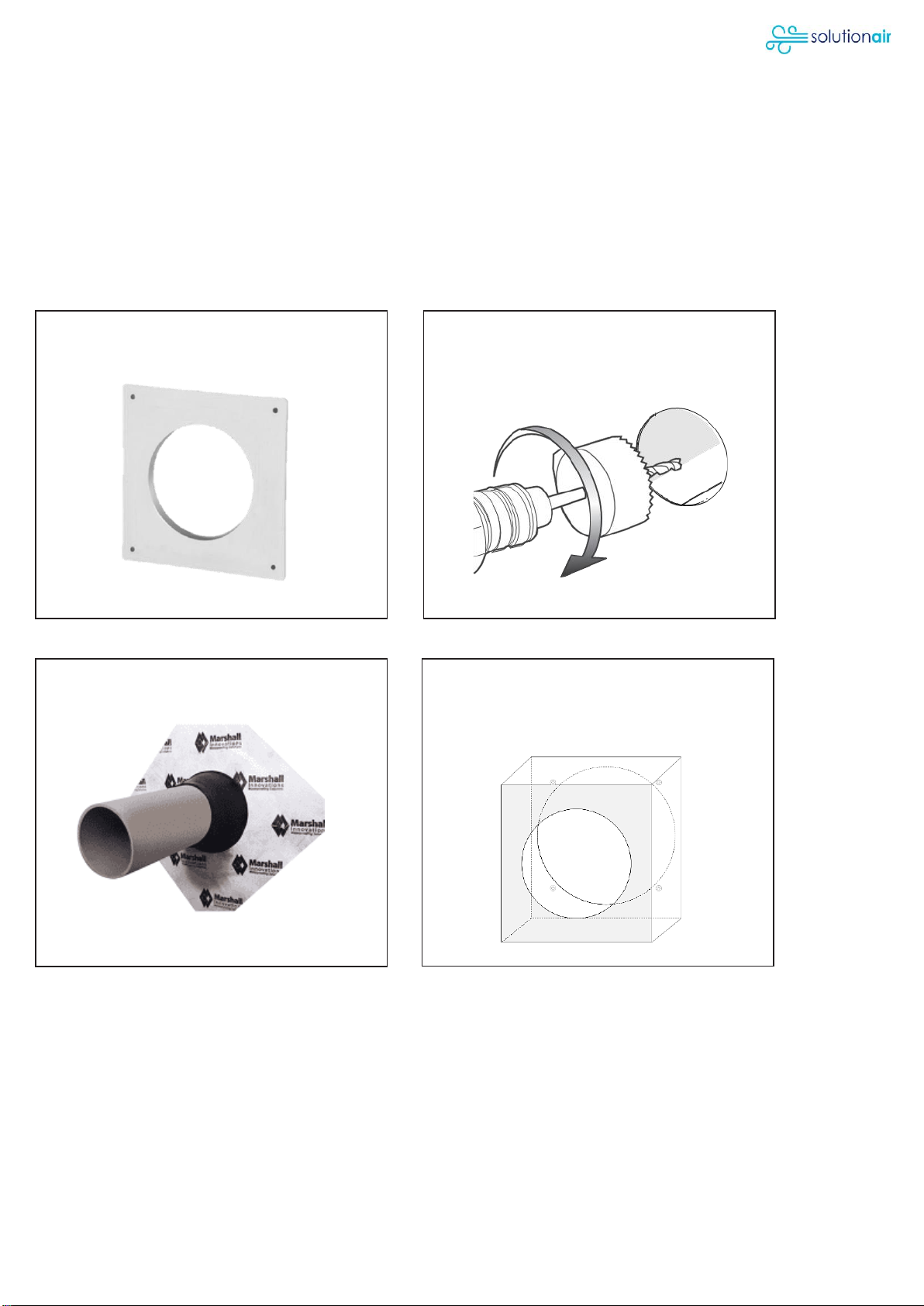
INSTALLATION ADVICES
Wall Mounting Bracket Hole Diameter 110 mm
External Waterproof Membrane & Tube External Cowling (Plenum)
Drill or cut a 110mm hole through wall with a
2° slope towards outside.
(If required, remove temporary the wall
mounting bracket)
Choose location and install wall mounting
bracket from inside before installing the gib
board.
Install duct and trade seal from outside
with a 2° slope for weathertight connection.
Install external cowling from outside with the
bigger hole against the trade seal and the
slope on the top. Consider to drill a small
drain hole if cowling is exposed to rain.

Page 9 / 17
Wiring to and from switch Power Supply Plate
Electrical Connection Power Supply Plate Cover
External Vent Ceramic Core
Plan wiring from and to wall switch:
3 options to go through power supply plate.
(Switch is not included)
After installing the gib board over the
mounting wall bracket, cut out the whole
and line up the power supply plate on top.
Connect power supply plate in
accordance with wiring diagram.
(Only certified electricians)
Install power supply plate cover.
Install external vent on the cowling. Insert ceramic core into duct from inside.

Page 10 / 17
REC-Duo Unit External Cladding
WIRING DIAGRAM
Wiring diagram for 24h/7d operation
It is recommended to include a main switch to power off the whole unit for e.g. maintenance.
Insert the REC-Duo unit into the duct. The
power connectors need to line up and the
plate snaps into a magnetic mount.
Complete external cladding around the
cowling in accordance with NZ building
standards.
REC-Duo 100
REC-Duo 100 MHY
REC-Duo 100 RC PLUS

Page 11 / 17
TIMER AND HUMIDISTAT
Timer (TM) and humidistat (HY) threshold regulation
TM Timer
This function is present in the REC-Duo 100, REC-Duo MHY and REC DUO 100 PLUS RC models.
Adjust the trimmer TM (screw - red) to set the timer operating time (only extraction from 0 to 30 minutes).
HY Humidistat
This function is present in the REC DUO 100 MHY and REC DUO 100 PLUS RC models.
Adjust the trimmer HY (screw - blue) to set the humidity threshold (adjustable from 40% to 90% RH - Relative
Humidity) at which the appliance will automatically switch to a higher speed.
For New Zealand we recommend to set the level between 60% and 70% RH.
Page 12 / 17
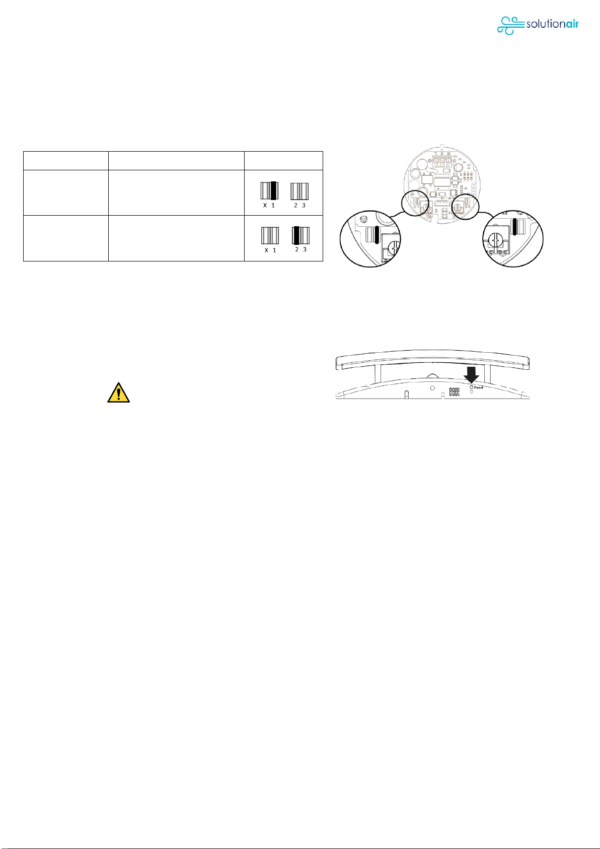
SPEED SELECTION
Selecting the 24h operating speed
REC-Duo 100 and REC DUO 100 MHY
Models with two possible operating speeds for continuous operation (24 h) with alternating flows (Push-Pull).
Select the speed simply by moving the jumper as shown in the figure below, to one of the two positions (see
table).
Jumper
Speed Setting
Jumper 1
Speed 1 (factory setting)
Jumper 2
Speed 2
REC-Duo 100 PLUS RC
Speeds can be selected and adjusted via remote control.
FIRST START-UP - PAIRING
Note
Use always the supplied awl key to press the "RESET" button
located at the base of the front support of the ventilation unit.
DO NOT USE METALLIC OBJECTS!
REC-Duo 100 and REC DUO 100 MHY
For optimum operation, installation in pairs is recommended.
DEVICE PAIRING
These devices must be connected to the same circuit and powered by the same switch. Once powered, they
start operating in extraction mode (Push), as shown by the green indicator light on the device. To synchronise
flows, change the mode from extraction to intake on one of the two devices by pressing the "RESET" button
located on the device whose rotation direction is to be changed.
The intake mode (pull) is identified by a yellow indicator light. After the initial start-up and synchronisation, the
devices store the assigned alternating rotation direction. They will not need to be re-synchronised.
REC-Duo 100 PLUS RC
For optimum operation, installation in pairs is recommended, up to a maximum of 6 devices.
DEVICE PAIRING
Once powered, they start operating in extraction mode (Push), as shown by the green indicator light on the
device. To synchronise flows, change the mode from extraction to intake on one of the two devices by pressing
the "RESET" button located on the device whose rotation direction is to be changed. The intake mode (pull) is
identified by a yellow indicator light. The devices communicate with each other wirelessly.
To activate communication within the system, synchronise the devices as indicated below.
Press the "RESET" button on each device for at least 3 seconds. The blue led will begin to flash. Perform the same
operation on all the installed devices within 60 seconds. When all LEDs turn green or yellow, the synchronisation is
complete. During this phase do not press any button on the remote control.
UNPAIRING A DEVICE
To cancel synchronisation between devices, press the "RESET" button for at least 3 seconds. The LED will turn BLUE
and start flashing slowly; release the button. Press the "RESET" button a second time for a further 3 seconds. The
LED will start flashing faster; release the button. Press the "RESET" button one last time for at least 3 seconds. The
LED will stop flashing and after a few seconds it will turn GREEN or YELLOW. The selected device is no longer

Page 13 / 17
synchronised with the other devices. If the MASTER device is removed (see "Legend of the ventilation unit status"),
cancel the synchronization of all installed devices. Then repeat the above sequence of re-synchronization of the
entire product group.
PAIRING REMOTE CONTROL TO THE VENTILATION UNIT
Press the "RESET" button on the device to be connected to the remote control, for at least 3 seconds. When the
LED flashes BLUE, synchronisation mode has begun. To confirm the pairing, press any button on the remote
control (except the "0” key). The pairing is complete.
UNPAIRING REMOTE CONTROL FROM THE VENTILATION UNIT
Press the "RESET" button on the device to be disconnected from the remote control, for at least 3 seconds. When
the LED flashes BLUE, synchronisation mode has begun. To unpair, press any button on the remote control
(except the "0” key). The cancellation of the pairing is complete.
PAIRING A REMOTE CONTROL WITH SEVERAL VENTILATION UNITS
It is possible to control several REC DUO 100 RC ventilation units (maximum 6 units) with a single remote control. In
this case, all the remote-control functions, including the "Timed Boost", will work on all the ventilation units.
REMOTE CONTROL
REC-Duo 100 PLUS RC only
The product is a radio transmitter designed for operating the REC-Duo 100 PLUS RC.
ACTIVATING THE REMOTE CONTROL
Remove the transparent pull tab from the remote-control battery
compartment. The remote control is enabled to operate in a
radius of approximately 20m with the battery in a good
functioning state. To synchronise the remote control with the
product, refer to the “FIRST START-UP –PAIRING” instructions.
DESCRIPTION OF CONTROLS
0 - ON/OFF
Device on/off.
1 - PUSH-PULL MODE¹
24 h operation at the set speed. Automatic: operation with
alternating flow.
2 - SPEED 1¹
Low speed setting.
3 - SPEED 2¹
High speed setting.
4 - TIMER-SET BOOST²
Timer-set operation in ejection only at maximum speed.
5 - SLEEP MODE¹
Maintains the selected operating mode at the set speed 1. To exit
this mode before the end of the 8 hours, press any key (except 0).
6 - FORCED FLOW CONTROL¹
The devices operate either in ejection only or in injection only.
Press once: ejection mode. Press twice: injection mode.
7 - FREE COOLING (no inversion)¹
No inversion of flow. Press once: flow inversion stops in the
direction of rotation active at that moment. Press twice: all the
devices invert flow and maintain this set direction of rotation.
1: Function that controls all products paired with the remote control.
2: Function that controls the single product paired with its own remote control (not valid if only one remote control is used on
several devices - see paragraph "PAIRING A REMOTE CONTROL WITH SEVERAL VENTILATION UNITS").
LED Indication Signal:
Every time a button is
pressed an LED light on
the remote will indicate
that the command has
been received.

Page 14 / 17
SPECIFIC FUNCTIONS OF THE REMOTE-CONTROL REC DUO 100 PLUS RC
RESTORE FACTORY SETTINGS
Press for a few seconds and simultaneously release the 0, 1, 6 and 7 KEYS on the remote control. The LED will
flash RED and PURPLE. When they stop flashing, the devices will return to the previous mode, but with the
factory-set values.
CUSTOMISATION OF FACTORY SETTINGS
To increase and/or decrease the limit values, press and release the keys repeatedly as shown below.
SPEED ADJUSTMENT 1 - KEYS 2
Speed 1 can be set between 30% and 70%. In the factory settings mode, this value is 30%. The setup is reflected
on all synchronised devices.
Sequence:
1. Select KEY 2 - SPEED 1.
2. To enter SETUP MODE, press KEY 2 and KEY 3 simultaneously for a few seconds. The
STATUS LED on the product indicates when this mode is activated by FLASHING
BLUE.
3. Press KEY 2 to reduce the speed or press KEY 3 to increase it. The increase or
decrease in speed is shown by the respective increase or decrease in the
frequency with which the BLUE LED flashes. During the speed adjustment phases,
if you want to increase or decrease the previously set one, between one signal
and the other (flashing blue), a red visual signal is interposed which indicates that
the signal has come to fruition.
4. Press the 0 KEY to exit the SETUP MODE or alternatively wait about 10 seconds
without pressing anykeys.
NB: During the speed adjustment phase, the full-scale value is highlighted by a
GREEN light signal.
SPEED ADJUSTMENT 2 - KEYS 3
Speed 2 can be set between 70% and 100%. In the factory settings mode, this value is approximately 90%. The
setup is reflected on all synchronised machines.
Sequence:
1. Select KEY 3 - SPEED 2.
2. To enter SETUP MODE, press KEY 2 and KEY 3 simultaneously for
a few seconds. The STATUS LED on the product indicates when
this mode is activated by FLASHING PURPLE.
3. Press KEY 2 to reduce the speed or press KEY 3 to increase it.
The increase or decrease in speed is shown by the respective
increase or decrease in the frequency with which the PURPLE
LED flashes. During the speed adjustment phases, if you want
to increase or decrease the previously set one, between one
signal and the other (flashing purple), a red visual signal is
interposed which indicates that the signal has come to fruition.
4. Press the 0 KEY to exit the SETUP MODE or alternatively wait
about 10 seconds without pressing any keys.
NB: During the speed adjustment phase, the full-scale value is
highlighted by a GREEN light signal.
LED INTENSITY ADJUSTMENT
The brightness of the LED on the product is adjustable from maximum to off. This parameter can be set
individually on each REC DUO 100 PLUS RC.
Sequence:
1. Press KEY 4 and KEY 5 simultaneously for a few seconds to enter SETUP MODE. The STATUS LED on the product
indicates when this mode is activated with a PURPLE light.
2. Press KEY 2 to reduce the brightness or press KEY 3 to increase the brightness. The increase or decrease of the
brightness value is shown by the respective increase or decrease of the LED brightness.
3. Press the 0 KEY to exit the SETUP MODE or alternatively wait about 10 seconds.
Page 15 / 17
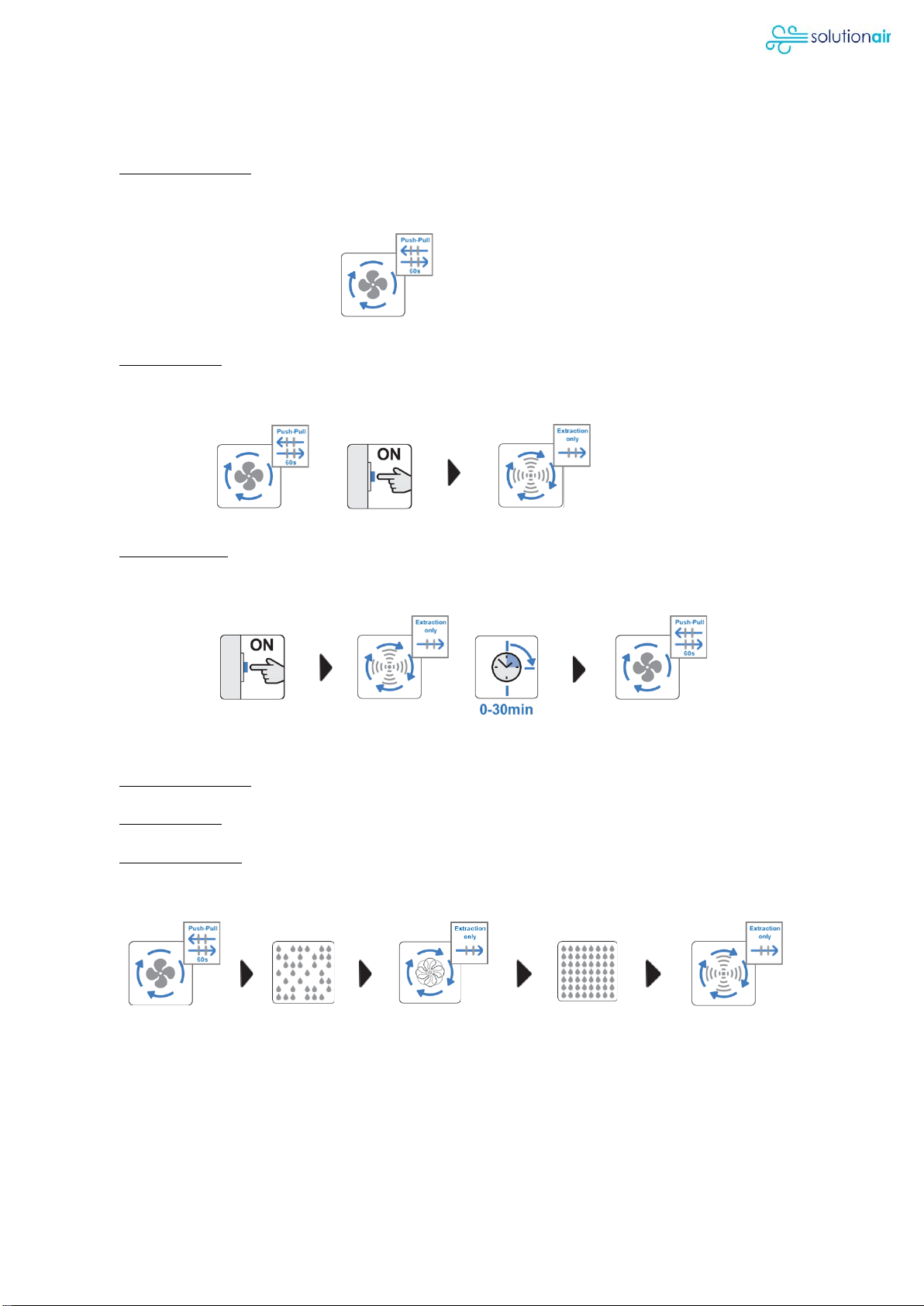
MODESL & OPERATION
REC-Duo 100
(I) 24h/7d operation: Alternating flow heat recovery mode (push-pull) at one of the two
fixed speeds that can be selected in the installation phase (see paragraph SPEED
SELECTION).
(II) Manual Boost: For faster air circulation, it is possible to activate the maximum speed
(boost) that only works in extraction, via remote control (light switch or dedicated switch
or RLS switch - not included in the supply).
(III) Boost duration: Adjustable timer is provided for setting maximum speed (boost) duration
from 0 to 30 minutes (see paragraph TIMER AND HUMIDISTAT). At the end of the timer
cycle, the unit automatically returns to the pre-set speed in 24-hour push-pull mode.
REC-Duo 100 MHY and PLUS RC
(I) 24h/7d operation: see REC DUO 100 (I)
(II) Manual Boost: see REC DUO 100 (I)
(III) Humidity control: Automatic faster air circulation (boost) with increase of humidity level.
Humidity threshold adjustable from 40% to 90% RH (see paragraph TIMER AND
HUMIDISTAT).
Once the room humidity is back to the pre-set level on the humidistat, the device
automatically switches to the 24-hour push-pull operating speed.

Page 16 / 17
LEGEND OF THE VENTILATION UNIT STATUS
LED
DESCRIPTION
STATUS
100
100
MHY
100
PLUS
RC
●
GREEN
EXTRACTION
●
●
●
●
YELLOW
INTAKE
●
●
●
●
RED
BOOST WITH TIMER
●
●
●
FLASHING RED
DIRTY FILTER NEEDS CLEANING
●
●
●
●
BLUE
MHY OPERATING
●
●
FADING BLUE
SLEEP FUNCTION OPERATING
●
FADING YELLOW OR GREEN
FREE COOLING (RC BUTTON 7)
●
FLASHING YELLOW OR GREEN
FORCED FLOW OPERATING
(RC Button 6)
●
FLASHING WHITE/LIGHT BLUE
RECEIVING COMMAND FROM RC
●
FLASHING RED/PURPLE
RESTORE FACTORY SETTINGS
●
●
PURPLE
LED INTENSITY ADJUSTMENT
●
FLASHING BLUE
DURING SPEED REGULATION 1
●
FLASHING PURPLE
DURING SPEED REGULATION 2
●
FLASHING LIGHT BLUE
SYNCRONISING DEVICES
CANCEL SYNCRONISATION
CANCEL RC PAIRING
●
FLASHING BLUE WITH EXTENDED
SEQUENCE
INDICATES A SLAVE UNIT
●
FLASHING GREEN
INDICATES A MASTER UNIT
●

Page 17 / 17
CLEANING AND MAINTENANCE
Do not use acid, corrosive or abrasive cleaners.
Do not use pressure washers, steam cleaning equipment.
We recommend replacing filters after a maximum of two cleanings.
RESETTING THE REPLACE/CLEAN FILTERS NOTICE (RED FLASHING LED)
Press the button "RESET" located at the base of the front support of the ventilation unit for more than 5 seconds.
When the LEDs turn violet, the reset successfully completed.
Use always the supplied awl key to press the "RESET" button.
DO NOT USE METALLIC OBJECTS!
CUSTOMER SERVICE
Contact:
Solutionair Customer Service
Email: enqui[email protected].nz
Phone: 0800 484 3269
This manual suits for next models
2
Table of contents
Popular Heating System manuals by other brands


MERK
MERK MEnV 180 Pro Operating & assembly instructions

Polypipe
Polypipe Silavent CMX Installation and operating instructions

nilan
nilan Combi 302 Polar Top Installation instruction

2VV
2VV ALFA 95 II vertical quick start

Etherma
Etherma EZ-800 Installation and operating instructions

Vectaire
Vectaire WHHRC180DC Installation, operating and maintenance instructions