2
Table of Contents
1General Information .................................................................................................................... 4
2Components and Materials of Construction ............................................................................. 4
3Regulations and Safety Instructions ......................................................................................... 5
4Application and Planning ........................................................................................................... 5
4.1 Application..................................................................................................................................................5
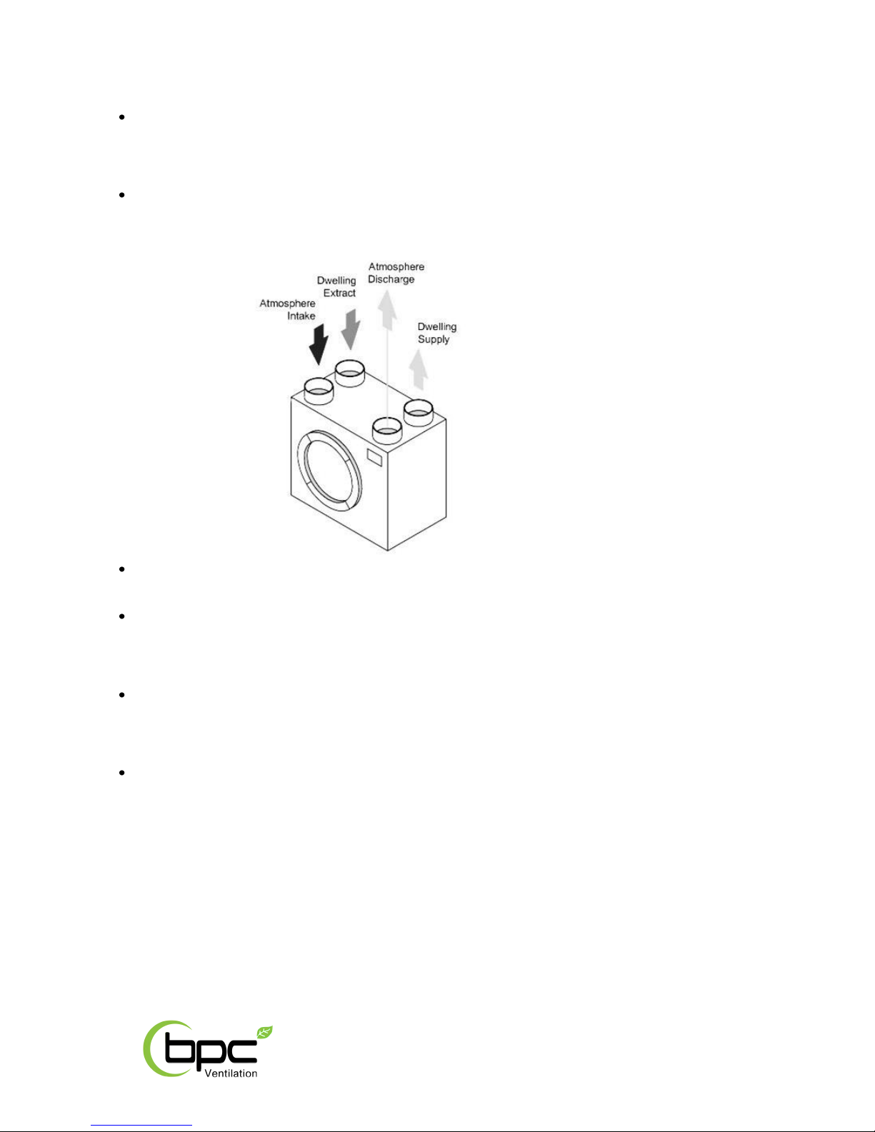
4.2 MVHR operation overview .........................................................................................................................5
4.3 MVHR installation planning........................................................................................................................6
5Installation ................................................................................................................................... 6
5.1 General information ...................................................................................................................................6
5.2 Impact noise reduction...............................................................................................................................7
5.3 Wall mounting the MVHR...........................................................................................................................7
5.4 Heat exchanger retaining bracket ..............................................................................................................7
5.5 Ducting........................................................................................................................................................7
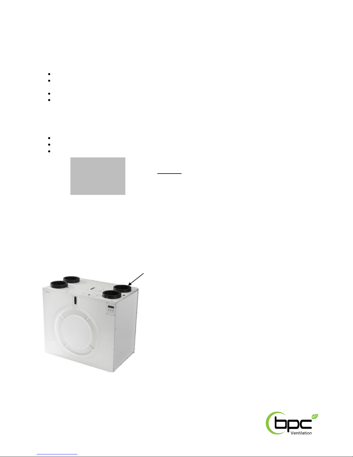
5.5.1 Duct connections........................................................................................................................................8
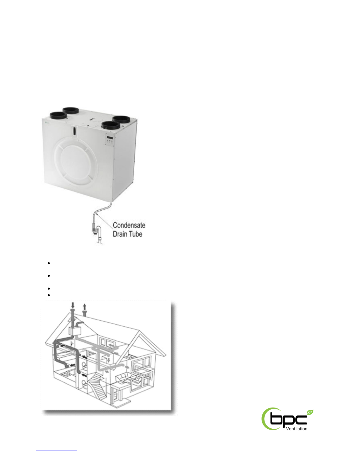
5.6 Condensate drain........................................................................................................................................9
5.7 Installation example ...................................................................................................................................9
5.8 Installation dimensions.............................................................................................................................10
5.8.1 Right hand installation..............................................................................................................................10
5.8.2 Left hand installation................................................................................................................................11
6Technical Data ........................................................................................................................... 12
6.1 Air flow settings (Xcell 400 QV model only) .............................................................................................12
6.2 Air flow settings (Xcell 400 QVW model only)..........................................................................................12
6.2.1 PCB port pins (Xcell 400 QVW model only) ..............................................................................................12
6.3 Air flow settings (Xcell 400 QVI model only) ............................................................................................13
6.4 Factory speed settings (All Xcell 400 models) ..........................................................................................13
6.5 Technical data...........................................................................................................................................13
6.6 Applied Energy accessories for manual or automatic MVHR operation ..................................................14
6.7 Applied Energy MVHR spares ...................................................................................................................14
7Electrical Wiring Diagrams ....................................................................................................... 15
7.1 Manual 2-speed switch (Xcell 400 QV model only)..................................................................................15
7.2 Automatic 3-speed switch (Xcell 400 QVW model only)..........................................................................16
7.3 Automatic 3-speed switch & CO2sensor (Xcell 400 QVW model only)....................................................17
7.4 Automatic 3-speed switch, CO2sensor & up to three humidity sensors (Xcell 400 QVW model only) ...18
7.5 Automatic 3-speed switch & up to four humidity sensors (Xcell 400 QVW model only).........................19
7.6 MVHR automatic control –connection PCB (Xcell 400 QVI model only).................................................20
7.7 CO2sensor (Xcell 400 QVI model only).....................................................................................................21
7.8 Humidity sensor (Xcell 400 QVI model only)............................................................................................22
7.9 7-day timer switch (Xcell 400 QVI model only) ........................................................................................23
7.10 Smoke alarm (Xcell 400 QVI model only) .................................................................................................24
7.11 RF Receiver (Xcell 400 QVI model only)....................................................................................................25
7.12 RF Transmitter (Xcell 400 QVI model only) ..............................................................................................25
7.13 Main MVHR PCB (Xcell 400 QVI model only)............................................................................................26
8Controller Functions ................................................................................................................. 26
8.1 Manual 2-speed switch (Xcell 400 QV model only)..................................................................................26
8.2 Automatic 3-speed switch (Xcell 400 QVW model only)..........................................................................27
8.3 CO2sensor (Xcell 400 QVW model only) ..................................................................................................28
8.4 Humidity sensor (Xcell 400 QVW model only) .........................................................................................28
8.5 Control panel (Xcell 400 QVI model only) ................................................................................................29
8.5.1 Control panel –normal operation............................................................................................................29
8.5.2 Control panel –main menus ....................................................................................................................29
8.5.3 Control panel –summer bypass temperature (settings menu) ...............................................................30
8.5.4 Control panel –filter cleaning or replacement reminder (settings menu) ..............................................30
8.5.5 Control panel –operational dimensions menu........................................................................................31