Table of contents
Table of contents ............................................................................................................................2
Figure table ....................................................................................................................................2
Introduction..................................................................................................................................... 3
Power supply..................................................................................................................................4
Assembly of Combi 302 Polar......................................................................................................... 5
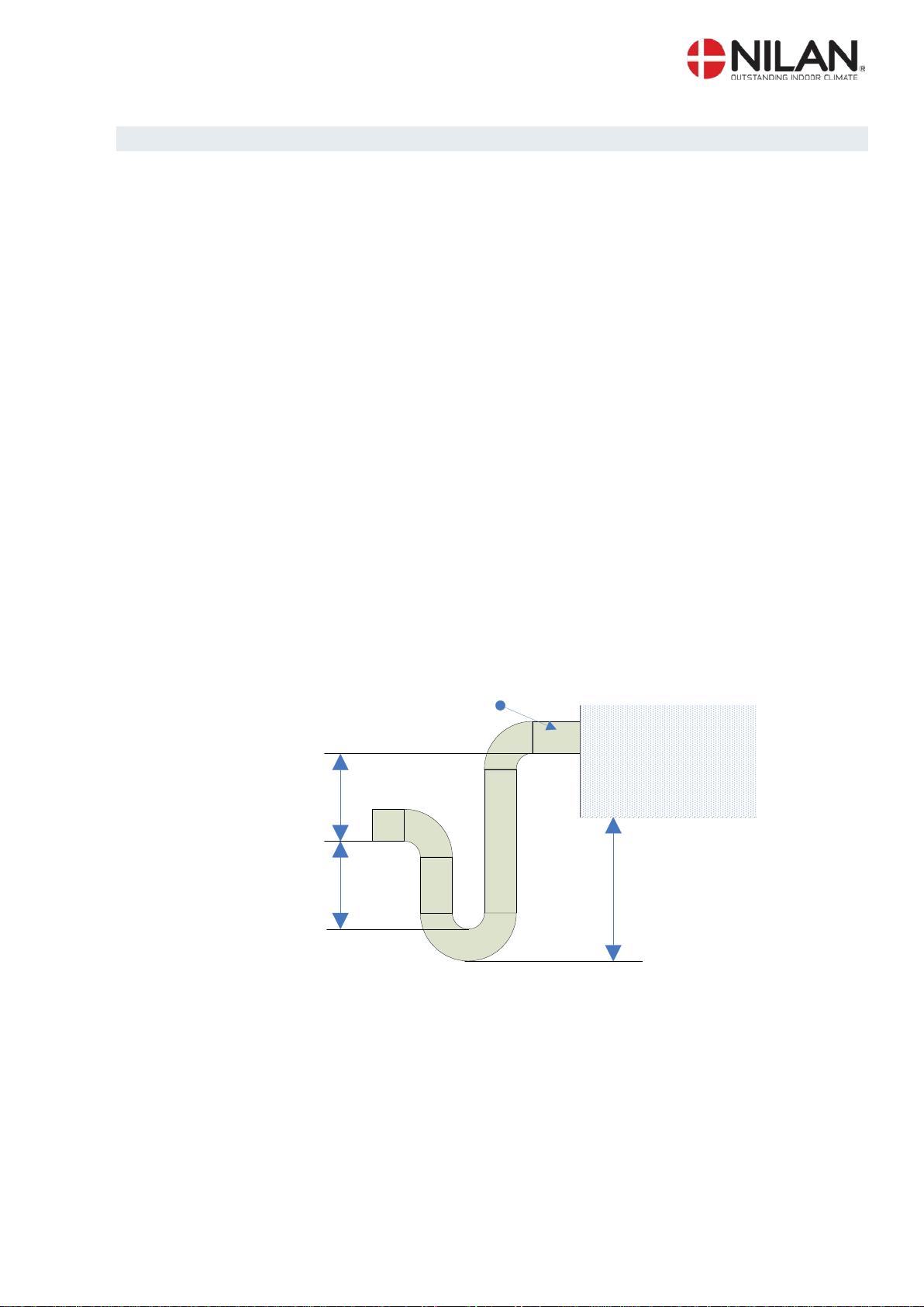
Condensation drain / water seal ..................................................................................................... 6
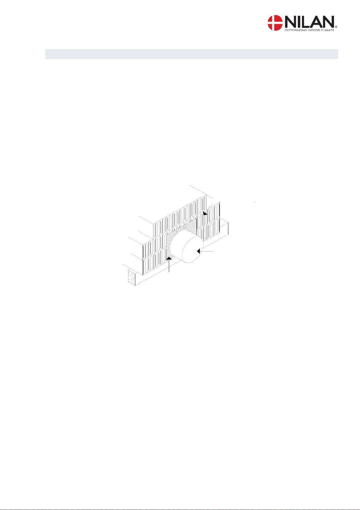
Ducting...........................................................................................................................................7
Starting and set up of the CTS 602 control..................................................................................... 8
Starting.......................................................................................................................................8
Set up of the CTS 602 control..................................................................................................... 8
Activating the SERVICE menu.................................................................................................... 9
Inlet heating.............................................................................................................................. 10
Heating surface......................................................................................................................... 11
Air quality.................................................................................................................................. 12
Air exchange............................................................................................................................. 13
Defrost......................................................................................................................................14
Temp. control............................................................................................................................ 15
Inlet control............................................................................................................................... 16
Room control ............................................................................................................................ 17
Restart......................................................................................................................................18
Preset....................................................................................................................................... 19
Manual......................................................................................................................................20
Modbus.....................................................................................................................................21
Datalog .....................................................................................................................................22
System dimension........................................................................................................................ 23
Accessories / spare parts ............................................................................................................. 24
Figure table
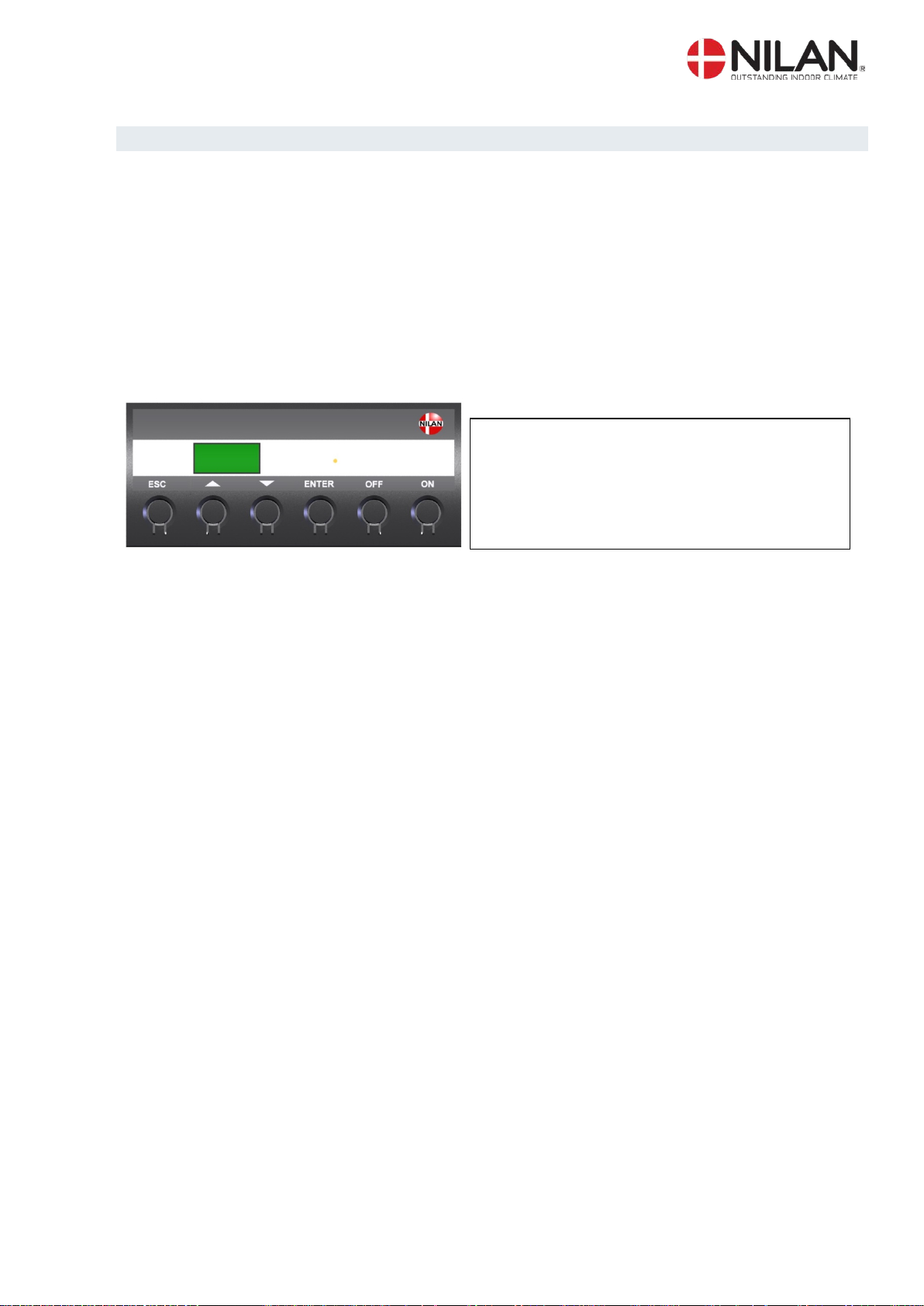
Figure 1: CTS 602 control............................................................................................................... 4
Figure 2: Mounting the Combi 302 Polar ........................................................................................ 5
Figure 3: Condensation drain / water seal....................................................................................... 6
Figure 4: Insulation of ducting.........................................................................................................7
Figure 5: CTS 602 control............................................................................................................... 8
Figure 6: Headlines in the service menu......................................................................................... 9
Figure 7: The "Inlet heating" Menu................................................................................................ 10
Figure 8: The “Central heating” menu........................................................................................... 11
Figure 9: The "Air quality" Menu................................................................................................... 12
Figure 10: The "Air exchange" Menu............................................................................................ 13
Figure 11: The "Defrost" Menu ..................................................................................................... 14
Figure 12: The "Temp. control" Menu ........................................................................................... 15
Figure 13: The "Inlet control" Menu............................................................................................... 16
Figure 14: The "Room control" Menu............................................................................................ 17
Figure 15: The "Restart" Menu ..................................................................................................... 18
Figure 16: The "Preset" Menu....................................................................................................... 19
Figure 17: The "Manual" Menu..................................................................................................... 20
Figure 18: The "Modbus" Menu .................................................................................................... 21
Figure 19: The "Datalog" Menu..................................................................................................... 22
Figure 20: System dimension ....................................................................................................... 23