Vectaire WHHRC180DC 5
Operation Chapter 4
4.1 Outline description
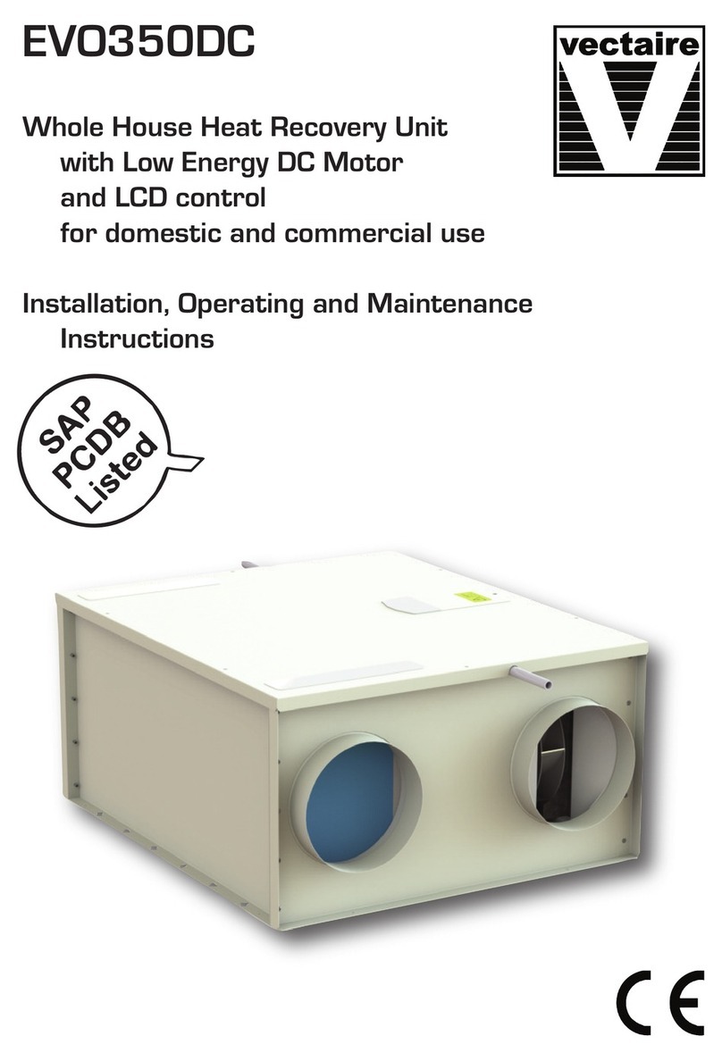
An appliance from the :++5&'& series is a highly advan
ced heat recovery unit, specially designed for minimum energy
consumption and maximum comfort. This is achieved with the
aid of various electronic control systems. A control unit with mi
croprocessor controls and monitors the safe operation of the
appliance and ensures that the air quantities remain constant
and at the preset values.
The :++5&'& comes with a control panel with display, ena
bling stepless adjustment of the volume without having to open
the appliance. Moreover, information regarding the operation
can be read out from the outside of the appliance.
4.2 LED display system and operating panel
7KH:++5&'&LV¿WWHGZLWKDFRQWUROSDQHO,WFDQ
be used to retrieve and modify the settings in the control unit
program.
The control panel has four keys and a display.
Control panel :++5&'&
1 = Display
.H\³2.´FRQ¿UPUHDG\¿OWHULQGLFDWLRQUHVHW
3 = Key increase parameter
4 = Function key
5 = Key decrease parameter
On the left the display indicates the ventilation setting or the
parameter type. On the right it shows the readout value, for
LQVWDQFHWKHSUHVHWDLUÀRZ
Example:
The display now shows that the
appliance is running at ventila
WLRQ VHWWLQJ DW D ÀRZ UDWH RI
150 m
3
/h.
The 4 keys have the following functions:
• F Function key / switching on and off parameter menu
• + Next parameter / increase value
3UHYLRXVSDUDPHWHUGHFUHDVHYDOXH
• OK Switching on and off settings menu / manual fault reset
¿OWHULQGLFDWLRQUHVHW
Other commands can be entered with key combinations.
)VHW FRQ¿UPSDUDPHWHUYDOXH
)UHVHW UHVHWSDUDPHWHUYDOXHWRIDFWRU\
setting
• OK & + (ON), switch on appliance
2.2)) VZLWFKRIIDSSOLDQFH
Everywhere in this booklet it applies that when a key has to be
pressed, the key in question is printed in quotation marks and
in bold.
([DPSOHSUHVVNH\³OK”
4.3 Frost protection
The frost protection system ensures that the secondary side
of the heat exchanger (outlet side) does not freeze up by in
WURGXFLQJDQLPEDODQFHEHWZHHQWKHLQOHWDQGRXWOHWDLUÀRZV
dependent on the outside air temperature and the pressure
across the heat exchanger.
4.4 Filter indication
7KHDSSOLDQFHLV¿WWHGZLWKD¿OWHULQGLFDWLRQV\VWHP,WLQGLFDWHV
RQWKHGLVSOD\ZKHQWKH¿OWHULVIRXOHG
For more detailed information refer to sections 7.2 and 8.1
