SOLUXTEC DMMVI370 User manual


2
SOLUXTEC USER GUIDE 2021_Version 1/a_ALL RIGHTS RESERVED
1. INTRODUCTION 3
2. BASIC SAFETY INSTRUCTIONS 3
3. REGULATION 4
4. TRANSPORTATION AND HANDLING 4
5. PRODUCT DETAILS 5
6. INSTALLATION 6
Modules Design 6
Precaution 8
Installation Option 10
7. ELECTRICAL INSTALLATION 13
Precaution 13
Installation Option 13
8. MAINTENANCE AND CLEANING 16

3
SOLUXTEC USER GUIDE 2021_Version 1/a_ALL RIGHTS RESERVED
1 INTRODUCTION
Thank you for electing SOLUXTEC GmbH PV modules. The following user guide covers
important instructions to be read and understood before installation of SOLUXTEC products.
This document does not have any relation to quality warranties and only acts as a user guide
for electrical, mechanical and general handling safety of SOLUXTEC products.
In case PV installation is not respecting below mentioned points, the quality warranty of
SOLXTEC products will become invalid.
This document belongs to SOLUXTEC and all content is SOLUXTEC intellectual property.
SOLUXTEC reserves the right to modify this document without prior notice.
- Please read this document carefully before installation
- Please make sure that this document is always available for installers and operators to
handle SOLUXTEC products.
- Please give a copy of this document to the installation owner.
- If any questions are not well answered in this document, please contact SOLUXTEC
support prior installation.
2 SAFETY
The installation of photovoltaic modules must respect the current standards from the
place of installation. It is imperative to refer to the standards of each local authority
in case specifics rules are imposed.
Installation of photovoltaic modules must be operated by qualified people with
sufficient knowledge of all regulations and compliance requirements specific to the
country of installation.
Solar modules create DC electricity and are even energized under a slight
illumination level. Several modules connected together may occur an accumulation
of voltage and intensity. Please respect all personal security to avoid a risk of
electrocution.
Please respect the data given from the elected module’s data sheet to respect all
module’s limits and comply with other materials that will be need to operate the
photovoltaic generator.
- Never open the junction box on the back of the photovoltaic module
- Make sure that connectors are clean and not dirty or wet before connection.
- Never disconnect the photovoltaic connector under load. Always turn off the DC breaker
prior to any photovoltaics connector disconnection.
- Tools must be dedicated for solar installation and supporting DC current.
- The final photovoltaic generator must follow all needed standards and requirements in
compliance with the installation country (PV, inverter, cable, grounding and other
accessories from the PV generator).
- Never disassemble any part of the module.

4
SOLUXTEC USER GUIDE 2021_Version 1/a_ALL RIGHTS RESERVED
3REGULATION
All modules presented in this document are covered by the following standards:
IEC 61215
IEC 61730
IEC 62804 (PID)
IEC 61701 (SALT MIST)
IEC 62716 (AMMONIA)
EMC and Low Voltage regulation
NOTE: SOLUXTEC is always improving its products. Please contact customer service if a
standard is missing for your project from the above list.
4 TRANSPORTATION AND HANDLING
During transportation and interim storage, following points have to be respected:
Transportation of the modules needs to be done only with SOLUXTEC original
packaging.
Never exceed the maximum number of pallets to be stacked. Only original SOLUXTEC
packaging is allowed for pallet stacking.
When unpacking modules, please wear soft and clean gloves. It is forbidden to use
suction cup to carry the module as it will damage the ento reflective coating for the solar
glass.
It is forbidden to carry/lift the modules from the solar cables or from the junction box or
any conductive elements.
Do not drop module directly on module.
While handling modules be cautious, especially on the corners to not shock them.
While handling the modules never scratch the anodised coating of the frame.
Corrosion may occur and cause mechanical resistance diminution.
It is forbidden to drill holes in the aluminium frames.
It is forbidden to paint the modules or to apply any adhesive on the module’s surface.
Never walk on the module.

5
SOLUXTEC USER GUIDE 2021_Version 1/a_ALL RIGHTS RESERVED
5 PRODUCTS DETAILS
This document is valid for all products below:
FRAMED
DAS MODUL MONO VI / X DMMVI / DMMX Single glass White / Black
DAS MODUL MONO DMM Single glass White/ Black
DAS MODUL POLY DMP Single glass White / Black
DAS MODUL MONO PURE GLASS
VI / X
DMMVIPG /
DMMXPG
Glass glass Transparent / black
DAS MODUL MONO VI GEMINI DMMVI_GEMINI
Single glass
Bifacial
Transparent
FRAMELESS
POWERSLATE MONO VI PSMVI Single glass Black/White/Transparent
POWERSLATE MONO VI PG PSMVIPG Glass glass Black/White/Transparent
Label explanation:
All Modules from SOLUXTEC have their own label on
back.
This label summarizes the module data sheet as
follows:
- Place of production
- Commercial name
- STC (standard test condition) data:
- Pmpp : Power in watt at maximum power point
- Isc : Short circuit Intensity in ampere
- Impp : Intensity in ampere at power point
- Voc : Voltage in volt in open circuit
- Vmpp : Voltage in volt at power point
For more details about mechanical or electrical module
behaviour, please refer to dedicated data sheet.
Serial number codification:
S T U V WW XX YYY ZZZZ, where:
- S = D for DAS MODUL
P for POWERSLATE
- T = F for foil module
G for Glass Glass module
- U = A for solar cell mono M6
B for solar cell mono M10
C for solar cell mono M3
D for solar cell poly 157 mm²
E for solar cell mono M6 Bifacial
F for solar cell mono M10 Bifacial
G for solar cell mono M3 bifacial
- V = 1 for production in FAB 1 Bitburg
2 for production in FAB 2 Trier
- W = month of production
- X = year of production
- Y = Production order number
- Z = Module number from above Production Order number.

6
SOLUXTEC USER GUIDE 2021_Version 1/a_ALL RIGHTS RESERVED
6 INSTALLATION ON SITE
When installing SOLUXTEC PV modules the following guidelines need to be respected on
site.
MODULE DESIGN PRESENTATION
- Frame design for M6 solar cells modules:
DMMVI
DMMVI_GEMINI
DMMVIPG
- Frame design for M10 solar cells modules:
DMMX
DMMXPG
1038 mm
1745 mm
4 x mounting
holes: 328 mm
4 x grounding
holes: 78 mm
1133 mm
1722 mm
4 x mounting
holes: 306 mm
4 x grounding
holes: 78 mm

7
SOLUXTEC USER GUIDE 2021_Version 1/a_ALL RIGHTS RESERVED
- Frame design for Poly and Mono M3 solar cells modules:
DMP
DMM
- Frameless Design for M6 solar cells Module Glass + Foil & Glass + Glass:
PSMVI (total thickness of 5,5 mm)
PSMVIPG (total thickness of 6,5 mm)
1005 mm
1665 mm
4 x mounting
holes: 291
mm
4 x grounding
holes: 78 mm
1033 mm
1740 mm

8
SOLUXTEC USER GUIDE 2021_Version 1/a_ALL RIGHTS RESERVED
PRECAUTION:
Operate Solar PV modules in a safe environment. Suitable and exempt of any risks.
Maximum height to operate the modules is4000 mabove the sea level
Please do not use any abrasive or chemical solution on the modules. Neither on
glass nor on aluminium frames.
Avoid direct contact with salt water.
Solar PV modules are not to be considered as a roofing substitute. Solar PV modules
alone cannot grant waterproofing for the roof.
Roof waterproofing can be obtained considering the addition of a PV module and a
BIPV* solution.
*building integrated photovoltaic.
Operating temperature from -40°C to 85°C.
The best efficiency will be obtained by optimising the angle of inclination and facing
the sun.
When electing final position of the PV modules it isrecommended toavoid any
potential shadowing that could result from building, chimney, trees and so on as it
could result in a significant energy loss.
SOLUXTEC’s PV modules can be installed only with mounting structures.
Mounting structures need to comply with any applicable laws specific to the country
of installation.
Modules need tobe installed on mounting structure following user guide developed
by manufacturer of mounting structure.
Respect a sufficient ventilation for the PV modules.
Respect mounting structure dilatation to avoid any extra mechanical stress on PV
modules.
Make sure to use a mounting structure material that won’t present any chemical
reaction on PV module frame (corrosion phenomena)
Clamp’s election is important and need tofulfill the minimum standards:
•Frameless module clamps need an EPDM protection to tighten on glass.
For each type of Frameless modules, a minimal length of 120 mm is mandatory.
•For each type of framed modules, a minimal length of 80 mm clamps is
mandatory.
•Clamps are not in contact with front glass, or clamps for frameless modules
are not shadowing solar cells.
•A minimum of 4 clamps/module is mandatory.
•Tightening force in Newton must follow recommendation of the clamp
producer.

9
SOLUXTEC USER GUIDE 2021_Version 1/a_ALL RIGHTS RESERVED
•When tightened, it is forbidden that clamps show a module frame
deformation.
When clamping, please make sure that force is homogenously shared on aluminium
part. Force cannot deform top frame flange. For module series equipped with a water
drain corner, clamp must not be applied directly on.
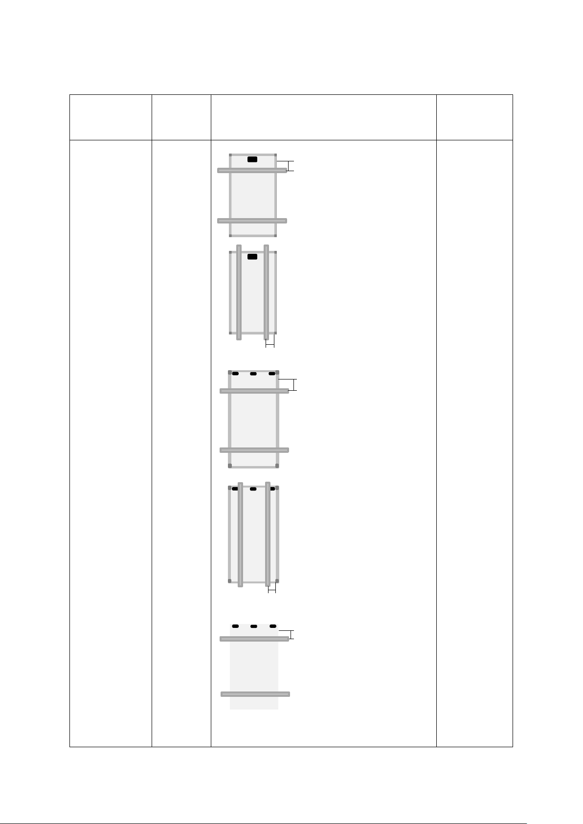
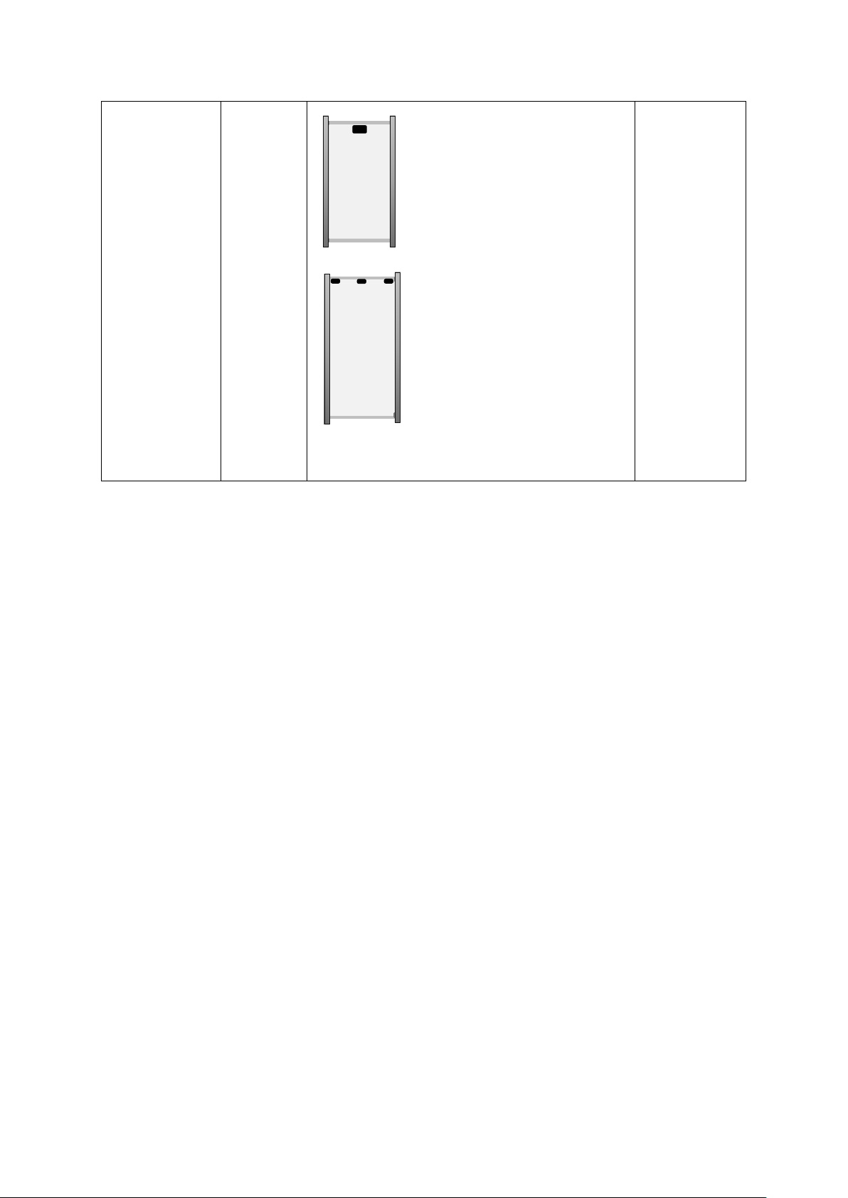
Please refer to the table on next page showing the different installation options from
SOLUXTEC’s module range. Please note as well that the mechanical behaviour from
our product will vary depending on the option elected.
Any solutions not shown in this table need to get an official validation from the technical
department prior installation.
10
SOLUXTEC USER GUIDE 2021_Version 1/a_ALL RIGHTS RESERVED
INSTALLATION OPTION
Installation
method
Module
Mounting system position (in mm)
Between X and Y
Mechanical
load test in Pa
(safety factor
of 1,5)
With Clamps
DMP
DMM
DMMIV
DMMX
&
DMMIVPG
DMMXPG
PSMVI
&
PSMVIPG
Test:
+8100/-2400
Design:
+5400/-1600
Test:
+2400/-2400
Design:
+1600/-1600
Test:
+8100/-2400
Design:
+5400/-1600
Test:
+2400/-2400
Design:
+1600/-1600
Test:
+2400/-2400
Design:
+1600/-1600
X = 200
Y = 410
X= 50
Clamps not in contact with plastic corner
Y = 250
X = 250
Y = 460
X= 50
Clamps not in contact with plastic corner
Y = 250
X = 350
Y = 460

11
SOLUXTEC USER GUIDE 2021_Version 1/a_ALL RIGHTS RESERVED
With mix
clamping
DMP
DMM
DMMIV
DMMX
&
DMMIVPG
DMMXPG
Test:
+2400/-2400
Design:
+1600/-1600
Test:
+2400/-2400
Design:
+1600/-1600
With Mounting
Holes
DMP
DMM
DMMIV
DMMX
&
DMMIVPG
DMMXPG
DMMIV
DMMX
&
DMMIVPG
DMMXPG
&
GEMINI
Test:
+8100/-2400
Design:
+5400/-1600
Test:
+8100/-2400
Design:
+5400/-1600
Test:
+2400/-2400
Design:
+1600/-1600
Y = 410
X = 200
X= 50
Clamps not in contact with plastic corner
Y = 250
Y = 460
X = 250
X= 50
Clamps not in contact with plastic corner
Y = 250
X = 291 mm
(4 positions)
X = 328 mm
(4 positions)
X = 328 mm
(4 positions)
12
SOLUXTEC USER GUIDE 2021_Version 1/a_ALL RIGHTS RESERVED
With insertion
Profile
DMP
DMM
DMMIV
DMMX
&
DMMIVPG
DMMXPG
&
GEMINI
Test:
+2400/-2400
Design:
+1600/-1600
Test:
+2400/-2400
Design:
+1600/-1600
All the data mentioned above is given based on module resistance. It is on the installer
to elect a mounting instruction having at least same behaviour as the module.
The whole solution needs to be evaluated by the solution supplier for the set “PV
module + mounting system + clamp system”.
All accessories such as bolt, screws and other metal parts are corrosion-proof and
exempt of any chemical reaction with the frame of the solar module.
Make sure that the module’s junction boxes are not in contact with any metal part
belonging to the mounting structure.
Make sure that module cables are not damaged and not in mechanical stress.
Make sure that the mounting system or any sharp component is not in contact with the
surface of the modules nor the foil or glass backside.
For plotless module frame
For plotless module frame
13
SOLUXTEC USER GUIDE 2021_Version 1/a_ALL RIGHTS RESERVED
7 ELECTRICAL INSTALLATION
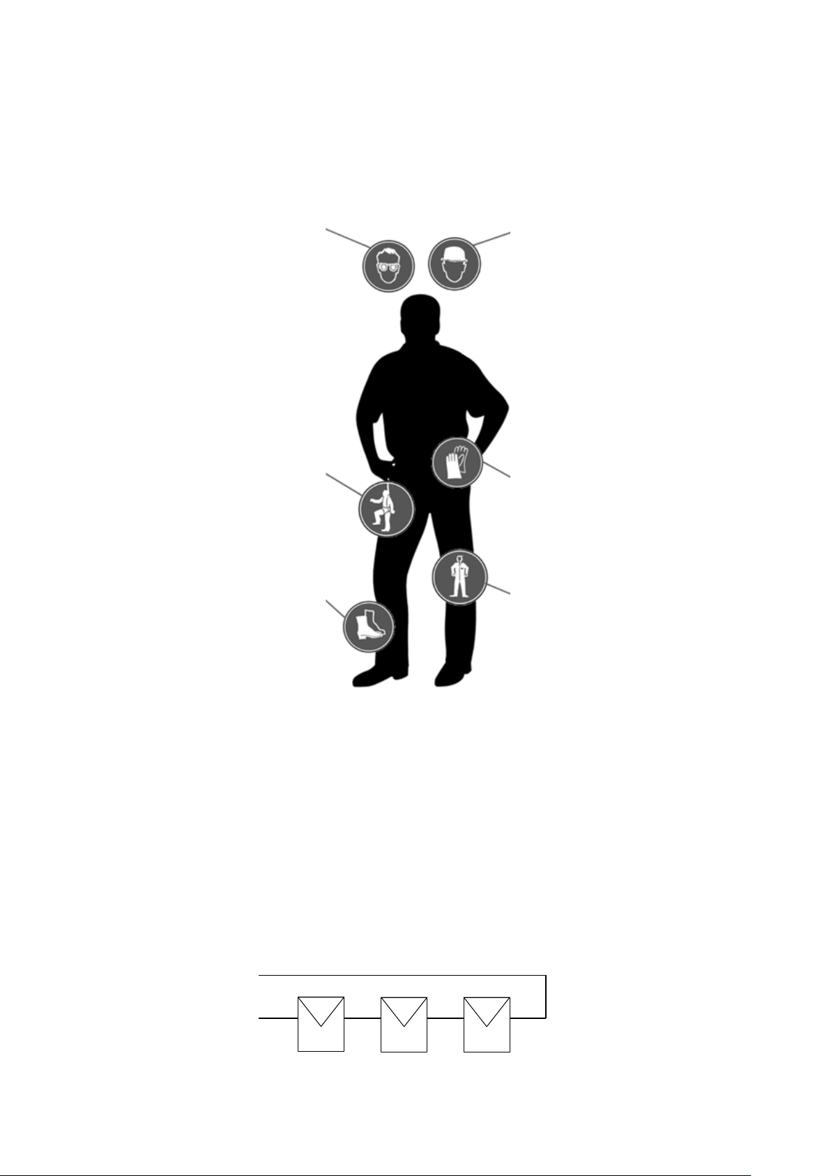
PRECAUTION for individual protection
Please make sure to wear your individual protection equipment.
WIRING AND PLANNING
Before starting with modules wiring, a visual inspection is recommended to make
sure that all module components are in a good shape.
The final wiring conception is determined in relation to the final project on site.
Modules deployed for a given project should present the same technical
characteristics to prevent any mismatching.
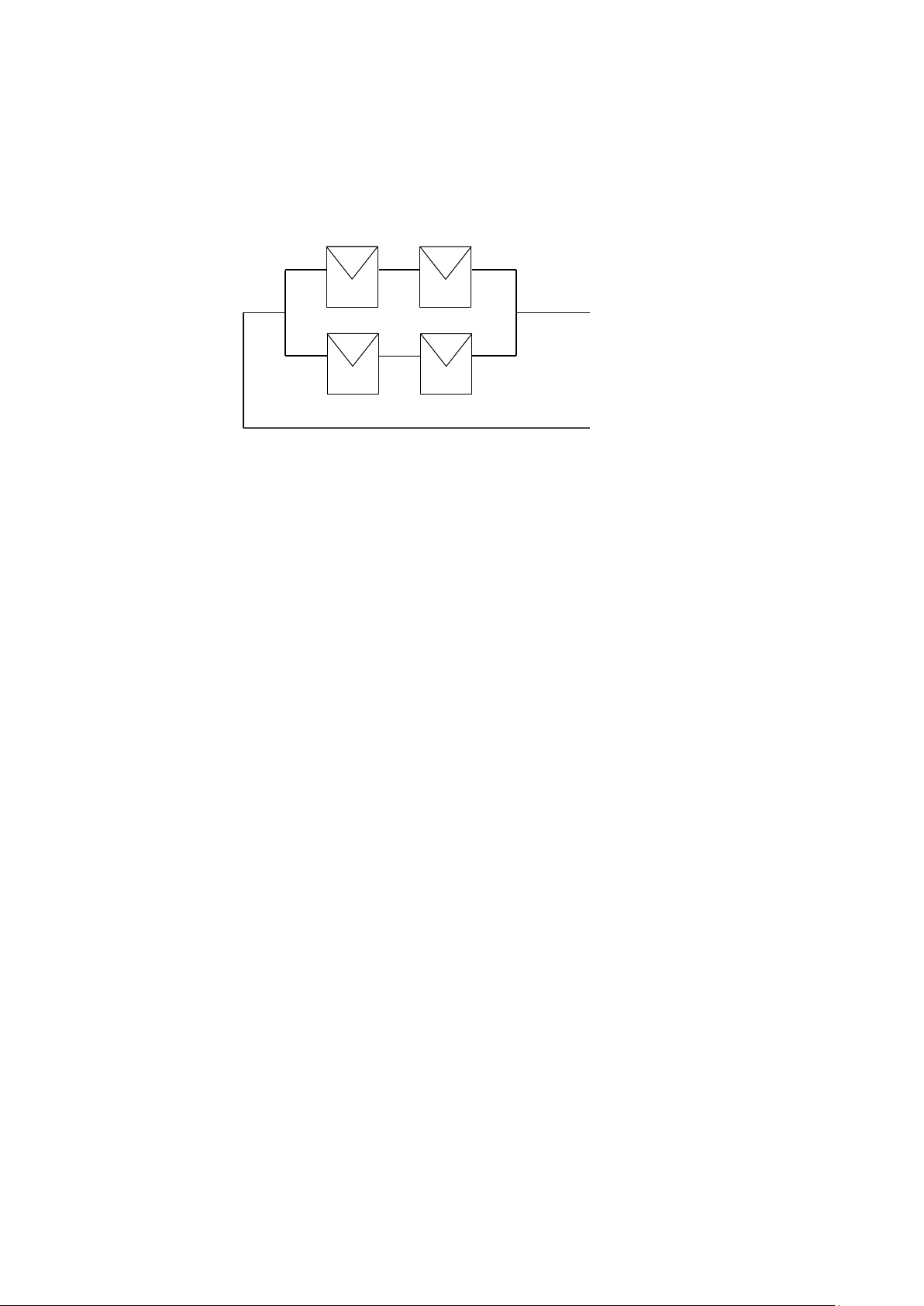
PV modules can be connected in serial or in parallel.
•In serial:
total voltage is the sum of each module voltage
(in serial we add voltage, we do not add
intensities)
helmet
Insulated gloves for
electrical work
Safety clothes
covering whole body
Security shoes
Fall protection for
height working.
Safety glasses
-
-
-
-
+
+
+
+
14
SOLUXTEC USER GUIDE 2021_Version 1/a_ALL RIGHTS RESERVED
•In parallel:
total intensity is the sum of the serial lines in
parallel (in parallel we add the intensities)
total voltage is the sum of each module voltage in
from 1 line (in parallel we do not add the voltage)
Note: When a project is wired with modules in parallel, it is important to check the fuse rating
of the module. This value is available on the module’s label as well as on the dedicated data
sheet. Indeed, in case of 1 line shadowing, the line that is still producing energy will “load” the
other. This is why an appropriate line fuse protection must be applied and follow appropriate
standards.
The maximal overall voltage of a PV generator needs to take into consideration the
worst-case scenario. It means that we need to consider the voltage open circuit and
the minimal temperature on site.
You can calculate it with the following formula:
=[1 + ( −25°)]
Where:
N=number of modules in serial
Uoc = Open circuit voltage of a module
TcUoc = Temperature coefficient at open circuit voltage
Tmin = Minimal temperature on project site
The cables section from our products is always given at 4mm², cables are always UV
resistant and qualified for direct current (DC). This section is enough for a single
component. However, and depending on the configuration of the pv generator, it is
recommended to check at the maximal short circuit current from the whole project in
order to elect the right cables cross section in respect to the local standards.
The planning for the wiring of the PV system should consider a tight loop wiring of the
plus and minus line. The area enclosed by the conductors should be kept as small as
possible (here in grey). This reduces the risk of inductive coupling caused by lightning
strokes.
-
-
+
+
+
-
-
-
+
+

15
SOLUXTEC USER GUIDE 2021_Version 1/a_ALL RIGHTS RESERVED
Connectors need to be kept dry and clean. When wiring connectors together, make
sure that both are from same manufacturer and same reference.
When well connected, you must listen a “click” confirming the right connection.
A bad connection may result into arcs and electrical shock. Arcs may also be the origin
of a fire departure. This point is extremely important.
All framed modules need to be connected together with a grounding solution to the
main equipotential bonding of the project location.
On each module, you can find 4 different location allowing the grounding bonding and
mark with this logo:
It is recommended to use a 10 mm² bonding connector to realize the grounding
between each module. The recommended section to the main equipotential bonding
is 16 mm².
The legal standard from the installation place might be different and need to be follow
in priority.
click
Frame

16
SOLUXTEC USER GUIDE 2021_Version 1/a_ALL RIGHTS RESERVED
8 MAINTENANCE AND CLEANING:
SOLUXTEC PV modules come with a long-lasting operating life coupled with low level
of maintenance.
SOLUXTEC recommends a yearly inspection from a qualified company (ideally from
the company having realised the installation) in order to control the efficiency of the
complete generator.
Dust or pollution from the environment may gather on the surface of PV modules.
Hence, it is recommended to clean the surface of the modules only with a soft broom
and water. An alcohol based cleaner solution is also allowed.
For any issues with SOLUXTEC’s products you can contact us via our email address
SOLUXTEC’S technical service will support you.

Table of contents
Other SOLUXTEC Solar Panel manuals


