5
Owner’s Information
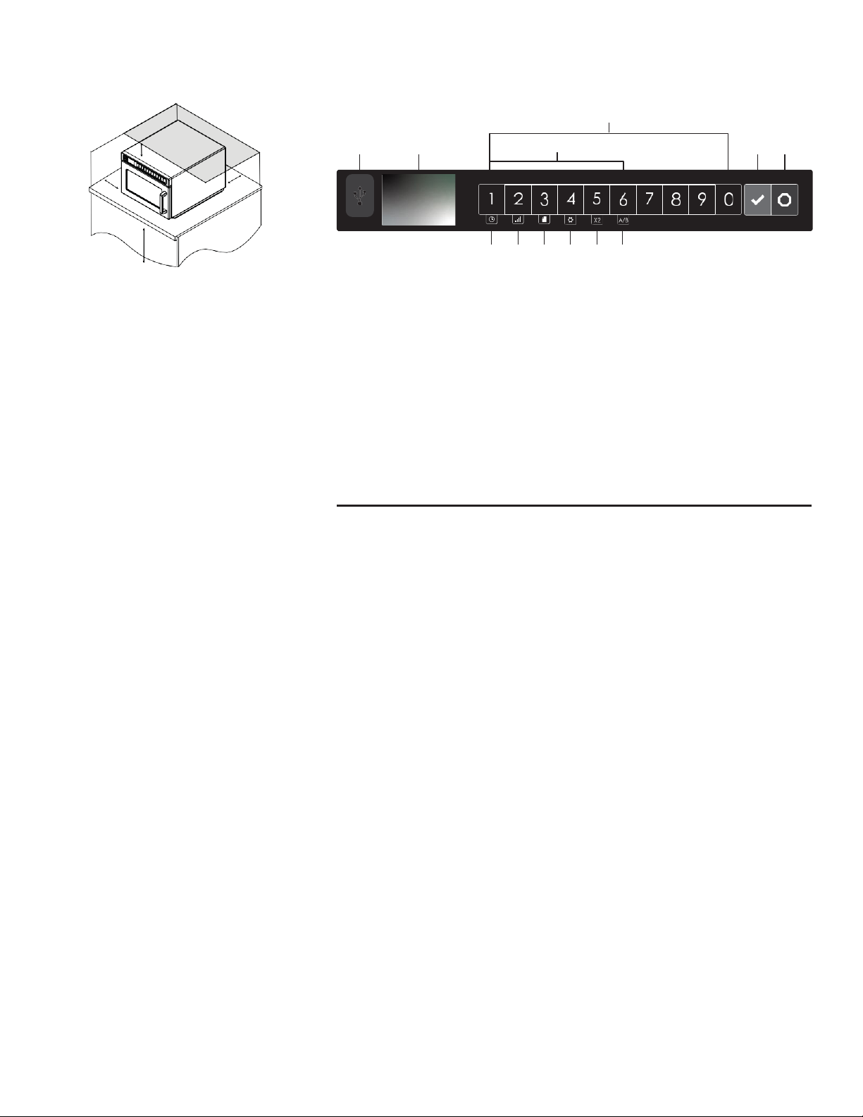
(C)
(i) (ii) ( iii) (iv) (v) (vi)
OVEN CLEARANCES
A.
Allow at least 2” (5.1 cm) of clearance
around top of oven. Proper air
flow around oven cools electrical
components. With restricted air flow,
oven may not operate properly and life
of electrical parts is reduced.
B.
SWAHD12 & SWAHD18 models:
There is not an installation clearance
requirement for the back of the oven.
SWAHD21: Allow at least 1” (2.54
cm) of clearance around back of
oven.
C.
Allow at least 1” (2.54 cm) of clearance
CONTROL PANEL FEATURES
(A)
USB Port
(B)
Display
(C)
Number Keypads
(D)
Start/ OK Keypad
(E)
Stop/ Reset Keypad
(F)
Secondary Function Keypads
To activate, press and hold corresponding
number keypad.
(i)
Manual Time Entry Mode (keypad “1”)
(ii)
Power Level (keypad “2”)
(iii)
Programming Mode (keypad “3”)
(iv)
User Options (number keypad “4”)
(v)
X2 - Double Quantity Cooking (keypad “5”)
(vi)
Menu A/B (keypad “6”)
around sides of oven.
D.
Install oven so oven bottom is at least
3 feet (91.5 cm) above floor.
Preset Program Keypads
To cook food using preprogrammed cooking
sequences:
1.
Open oven door, place food in oven,
and close oven door.
2.
Press desired number keypad(s).
3.
Oven operates and time counts down.
4.
At the end of the cooking cycle, the
oven beeps. Carefully remove food
from oven.
X2 - DOUBLE QUANTITY COOKING
1.
Press and hold number keypad “5”/ X2
to toggle double quantity feature ON.
“X2” appears at top center of screen
when enabled.
2.
Press desired number keypad(s).
Display counts down cooking time for
two quantities.
MENU A/B (select models)
Press and hold number keypad “6” to toggle
between A and B menus.
Manual Time Entry Mode
Time entry mode allows the user to manually enter cook time and power level, without
changing the preset program keypads.
1.
Open oven door, place food in oven, and close door.
2.
Press and hold number keypad “1”/ TIME ENTRY.
3.
Press number keypads to enter desired cook time.
4.
Press and hold number keypad “2”/ POWER LEVEL to change power level.
•
Press number keypads to enter % microwave power (“1”=10%, “2”=20%,etc.)
For 100% power level, press and hold number keypad “2”/ POWER LEVEL.
5.
Press START/OK keypad to begin cooking.
6.
At the end of the cooking cycle, the oven beeps. Carefully remove food from oven.
Programming Mode
1.
Press and hold number keypad “3”/ PROGRAM.
2.
Press number keypad(s) to open the desired program location.
3.
To edit name: Press number keypad “0”. Press number keypads to enter recipe name.
Press START/OK keypad.
4.
To edit cook time for Stage One: Press number keypad “1”. Press number keypads to
enter cook time. Press START/OK keypad.
5.
To edit power level for Stage One: Press number keypad “5”. Press number keypads to
enter % microwave power (“1”=10%, “2”=20%,etc.). For 100% power level, press and hold
number keypad “2”/ POWER LEVEL.
6.
If stage cooking is desired, repeat steps 4-5 for each additional stage, substituting
corresponding number keypads for each stage.
7.
To save and exit programming mode: Press START/OK keypad.