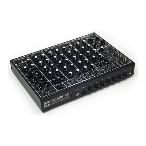
SOMA Pulsar-23 User manual

QUICK
START
Welcome, and thank you for purchasing
the Pulsar-23.
The purpose of this short manual is to
help experienced synth users who want
to start work with the Pulsar-23 quick-
er, without reading of the main manual,
to learn key hidden and non-common
functions that are hard to find and un-
derstand without an explanation. If you
have decided to use the QuickStart, it’s
supposed that the rest of the controls
and connectors are quite common and
clear for you or you can discover its func-
tions during simple experiments. Any-
way, it’s highly recommended to read
the main manual sooner or later as the
Pulsar is a complex machine with many
unique possibilities.
13
4
5 1 1 12 2 2 2
7 7 7 7
17 17
8
8
8
8
9
613 14 15 16 16
10
11
11
12
12

modulated. It should also be used when
a hard lock between the looper and the
clock divider is required in any modes
of operation.
RST in section CLOCK — resets the
clock-divider and looper. Its function is
to align the divider and loopers. Trigger-
ing this function prior to recording so
that loopers synchronize to the clock-di-
vider is recommended.
7
CLK pin
Inputs to a loopers individual clock
source.A pulsing signal, applied to these
pins will cause replacement of the hard-
wired clock with that individual one. The
full length of a looper is comprised of
128 clock impulses. The CLK pin is sen-
sitive and responsive to touch! Applying
a voltage through the body to these pins
will cause displacement of the loop. It
can be used as a loop altering effect. If
happy accidents are not desired, it can
be covered with pieces of the insulating
tube.
MIDI
LRN (Learn)
Buttons allow learning of incoming midi
signals and midi channels from the midi
DIN input on the back panel. By press-
ing the learn button next to a knob or
a channel then turning a knob/key on
your midi controller assigns Pulsar-23’s
drum channels/knobs/functions for ex-
ternal midi control. Drum channels and
the internal MIDI to CV converter auto-
matically identifies if a key or a knob was
activated. It makes a unique possibility
to control drum channels by continuous
controllers that give flexible control over
the channel’s attack, sustain, decay by a
simple drawing of the controller behavior
in a DAW.
This feature provides access for a DAW,
external sequencer or midi controllers to
perform detailed and complex automa-
tion over Pulsar.
MIDI CV
4-channel MIDI to CV converter.
If MIDI channel assigned to the bass
sound generator and MIDI channel as-
signed to the MIDI to CV converter num-
ber 1 are equal,the output 1 (marked KTR
—key tracking) will generate key-track-
ing signal according to input bass notes.
To make this assignment while holding
LRN button of the 1st MIDI to CV output
press any key on the keyboard assigned
to the bass channel.
For synchronization of the clock-divider
and the looper to an external MIDI signal,
set INT MIDI switch of CLOCK section to
MIDI position.
SHAOS
SHAOS is a unique and flexible pseu-
do-random generator based on shift
registers.
63-16-217—pseudo-random sequence
length selector. The length can be 63, 16
or 217 steps.
CLK — Clock input to synchronize the
pseudo-random generator to an external
source e.g. the clock-divider.
S/H—Input for the clock to sample and
hold. On the outputs marked “S/H” will
output synchronized signals with the
rising edges of the incoming CV signal.
Outputs DIR works independently from
LOOPER /RECORDER
1
ADD — record notes into the looper.
2
DEL — erase notes in the looper.
In Record Mode:
• ADD—worksinoverdubmode
• IfholdingdownDELandpressingADD,
then erase and record are activated at
the same time so you have a kind of
punch-in mode.
In Play Mode:
• ADD—Playoverapre-recordedse-
quence or trigger sounds without al-
tering the recording.
• DEL—Mutenoteswithoutalteringthe
recording.
REC.CONT Module (Recorder Control)
3
BANK—is a multi-functional button
4
L— is a multi-functional button
5
M— is a multi-functional button
• Press-HoldingtheBANKbuttonwhile
pressingADDorDELofonefromfour
drum channels will select 1 of 4 avail-
ablebanksofloops.Eachbankcon-
tains 4independent loops (one for
each drum channel).
• Press-HoldingtheBANKbuttonand
pressingADD+DELofonefromfour
drum channels will select a new bank
of loops while copying content from
the previous bank to the selected
one “on the fly” ie during a real-time
playing. Pressing these buttons com-
bination once again will continue this
copying from the current point. It al-
lows creating cool punch-in recordings
from one bank to another.
Сopying will be performed only on
those channels where the recording
mode is turned on.
• PressingtheBANKbutton+L(STOP)
stops a looper from playing.
• Ifpress-holdingtheBANKbutton+
M(START)andpressingADDorDEL
on one of the channels, the looper will
begin playback from 1 of 8 designated
sections.Eachchannellooperisdi-
vided into 8 equal partitions eg: sec-
tions.The8ADDandDELbuttonson
4 channels represent the 8 sections/
partitions linked to it.
• If press-holding BANK+L+M and
pressingADDorDELononeofthe
channels will perform quantisation of
this channels by 16”.
In Record Mode:
L and M control velocities of recorded
notes.
L — Low Velocity
M — Medium Velocity
L+M — High Velocity
In-Play Mode:
L and M change the velocity of previously
recorded notes.
6
LRST (Looper ReStarT)
Applying positive voltage to this pin will
trigger a restart of a looper. A common
purpose for this pin is to sync-lock the
looper to the clock-divider. In a typical
scenario, LSRT should be connected to
the 0.25 value pin of the clock-divider.
Connection of LSRT to a smaller divider
value (0.5 1 2 4 ,etc) shortens a loopers
length. This connection, synchronization
should be used if the clock rate is to be

S/H with SHAOS internal clock. If there’s
no incoming signal to S/H it then oper-
ates from SHAOS internal clock.
1,2,3 BIT—resolution in bits for SHAOS
outputs. A 1-bit output has 2 levels of
the output signal, 2 bit — 4 levels, 3 bit
— 8 levels.
DATA —Input allowing the recording of
16 step cycles into SHAOS. For this to
function “16” should be selected from
the 63-16-217 switch selector.
FX
2-channel independent FX processors
comprising of reverb and delay.
DLY REV (FX)—switch determines which
effect is assigned to the FX sub-mix bus.
The FX knob within a sound channel de-
termines the amount sent to either of
the 2 selected FX channels.
BPF DBL PCH (bandpass filter, double,
pitch) — switch for selecting effects:
BPF 1st ch — delay with a tweak-able
band-pass filter in feedback. 2nd ch —
Reverb
DBL 1st ch—double delay. 2nd ch—Re-
verb
PCH 1st ch — delay with a tweak-able
pitch shifter in feedback. 2nd ch—Reverb
with a pitch shifter in feedback.
MAD! Stereo — with BPF and PCH ef-
fects, MAD! brings out crazy behavior of
the FX processor. With the DBL position
of the switch, engages the stereo op-
eration of the FX processor. The stereo
signalissenttoDLYoutput(L)andREV
output (R) pins of the FX section.
T For continuous mad or stereo op-
eration connect this pin with the pin
“+10v” that is a constant +10 volts
output.
DLY REV—independent inputs and out-
puts for the 2 FX processors.
CLK MOD — Modulation input for the
DSP clock of the FX processors.
LFO
SYNC — Sync input. The rising edge of
an incoming signal will restart the LFO.
SYNC allows the LFO to sync to the clock
divider or one of the drum channels. To
trigger the LFO from a channel use the
TRIG pin.
ADDITIONAL MODULES
ANDFUNCTIONS
8
4 Attenuators that can be used to
control audio or CV signals.
9
8 Euro-rack format 3.5mm input
jacks to 8 pins adapters.
10
Individual diode for live circuit
bending.
11
Individual capacitors with a value
of 0.1uF and 10uF for live circuit bending.
12
Impulse/Signal Transformer. Con-
verts an incoming sustained signal to a
fast decaying shaped impulse suitable
for triggering of a drum sound. The main
purpose of it is to create straight drum
lines using clock divider as a rhythm
source. For making it connect the ap-
propriate value from the clock divider
via the transformer to the trigger input
of the desired drum channel.
13
MIX IN
An additional external audio input that
sums into Pulsar’s internal audio mixer.
T To create a metronome, chose the
necessary value from the clock divider
and connect it via one of the attenuators
8
to MIX IN. For the fast making of the
metronome, you can connect the clock
divider output and MIX IN by fingers
using body conductivity.
VCA — Two controllable VCA’s through
CV amplifiers. Can be used with audio
as well as CV signals.
14
Inverter
Works with CV and Audio signals.
T Here it’s possible to create a Side-
ChainEffect.Eg:ConnectENVpinfrom
the BD ch to the inverter IN. The OUT
of the inverter connects to the CV pin
of the VCA. Connect a sound source to
the VCA input and the VCA output to
the MIX IN.
15
CV controlled Inverter.
Works only with CV signals as it has a
binary output (0 and 10v).
Can be used to invert triggering signals
andipabeat.Eg:replaceaquarter
note hi-hat pattern into an eighth note
pattern. This can be done by insert-
ing the inverter into the signal of the
clock-divider (a quarter note pulse) that
is connected to TRIG pin of the HHT
channel. Applying of a voltage higher
than +5v to CV pin of the inverter will
cause altering of HHT pattern from 4th
into 8th.
16
On-Off switches controlled by
CV signals. Can work with audio and
CV signals.
17
(CV) Dynamic touch sensors gen-
erating CV signals from 0 to 10v. Put a
finger between the sensors. Depending
on the pressure and humidity of the skin,
a 0–10-volt signal will appear at the CV
output.
ABBREVIATIONS
+10 v — DC 10 volt
AMT — amount
AT T — attack
BD — bass drum
CLK — clock
DEL — delete
DIR — direct
DLY — delay
ENV — envelope
FB — feedback
FR — frequency
FREQ — frequency
GND — ground
H— high
HHT — hi-hat
L— low
LRST — looper restart
LRN — learn
M— middle
MOD — modulation
OMG! — oh my God!
PRC — percussion
PWR — power
Q— resonance
REC — record
REC.CONT — recorder control
REL — release
REV — reverb
RST — reset
S/H — sample and hold
SD — snare drum
SYNC — synchronization
TRIG — triggering
VOL — volume
WTF? — self explanatory;)
Other manuals for Pulsar-23
1
Other SOMA Drum manuals
