■Setting Up
1. Assemble the KP65. As shown in the il-
lustration, remove the base attachment
wing bolts, washers and spring washers
(4 each) that are attached to the main
body, and use those to attach the base to
the main body. Only loosely tighten the
wing bolts in this step.
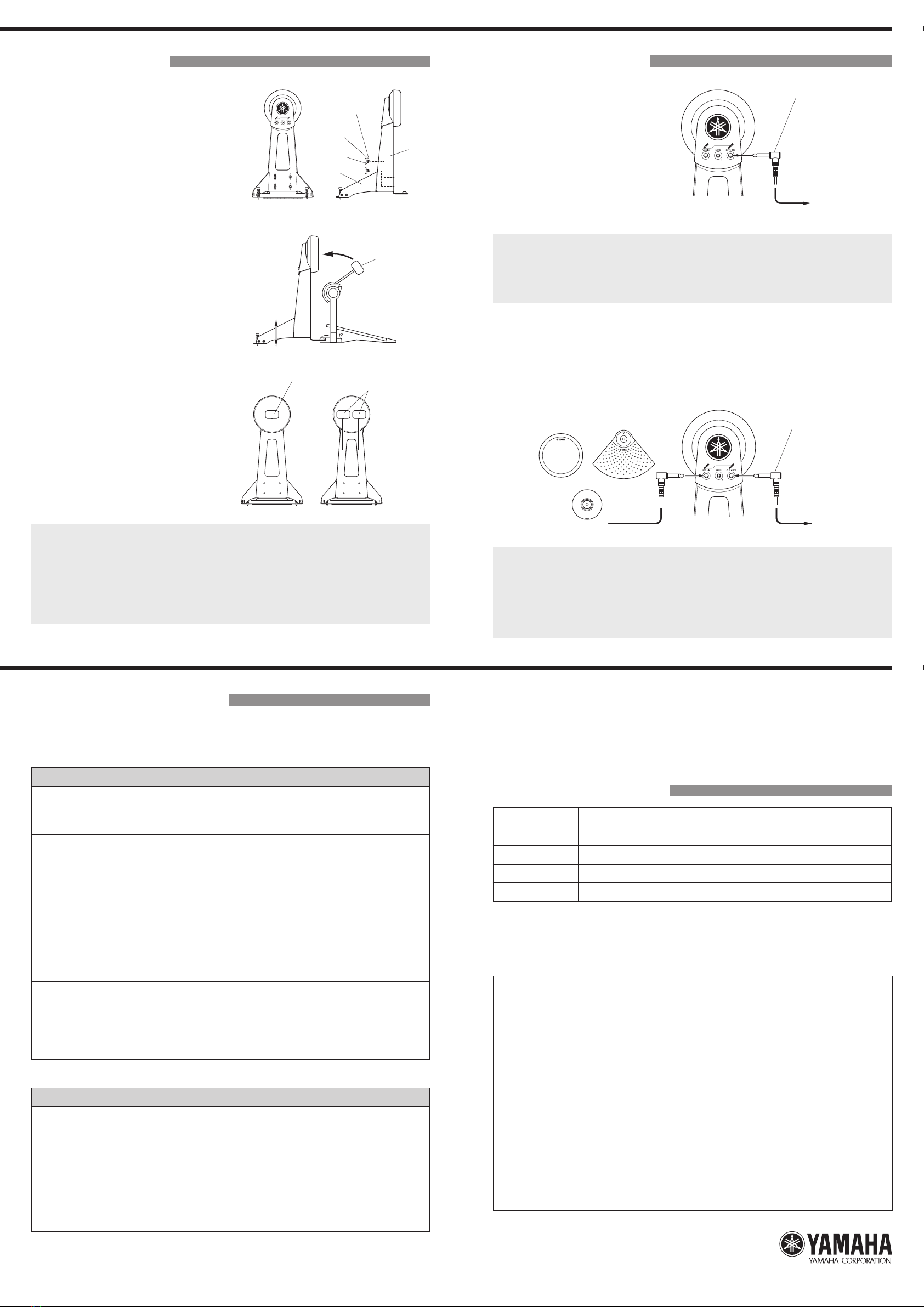
2. Attach your foot pedal to the KP65. Ad-
just the base's position so that the pad
surface of the KP65 is vertical when the
foot pedal is attached, and the KP65 is
stable when the beater hits the pad. After
the position is determined, firmly tighten
the wing bolts to secure.
3.
Adjust the position of the pedal and the length
of the beater shaft so that the foot pedal's
beater hits in the center of the kick pad.
NOTE: The KP65 can be used with a double foot pedal (YAMAHA DFP series etc). When using a double
foot pedal, please adjust the position of the pedal and the length of the beater so that the space
between the two beaters is positioned in the center of the pad.
NOTE: If the drum pads are set on a special purpose drum riser (optional), or if damage to the floor is not
a concern, extend the spurs so that the tip of the spurs dig into the riser or floor to prevent the
KP65 from moving about during performance.
NOTE:
If do not want to damage the floor, retract the spurs, place a mat or carpet under the KP65 and use
the strip of Velcro˛ attached to the underside of the KP65's base to prevent the KP65 from moving
during performance.
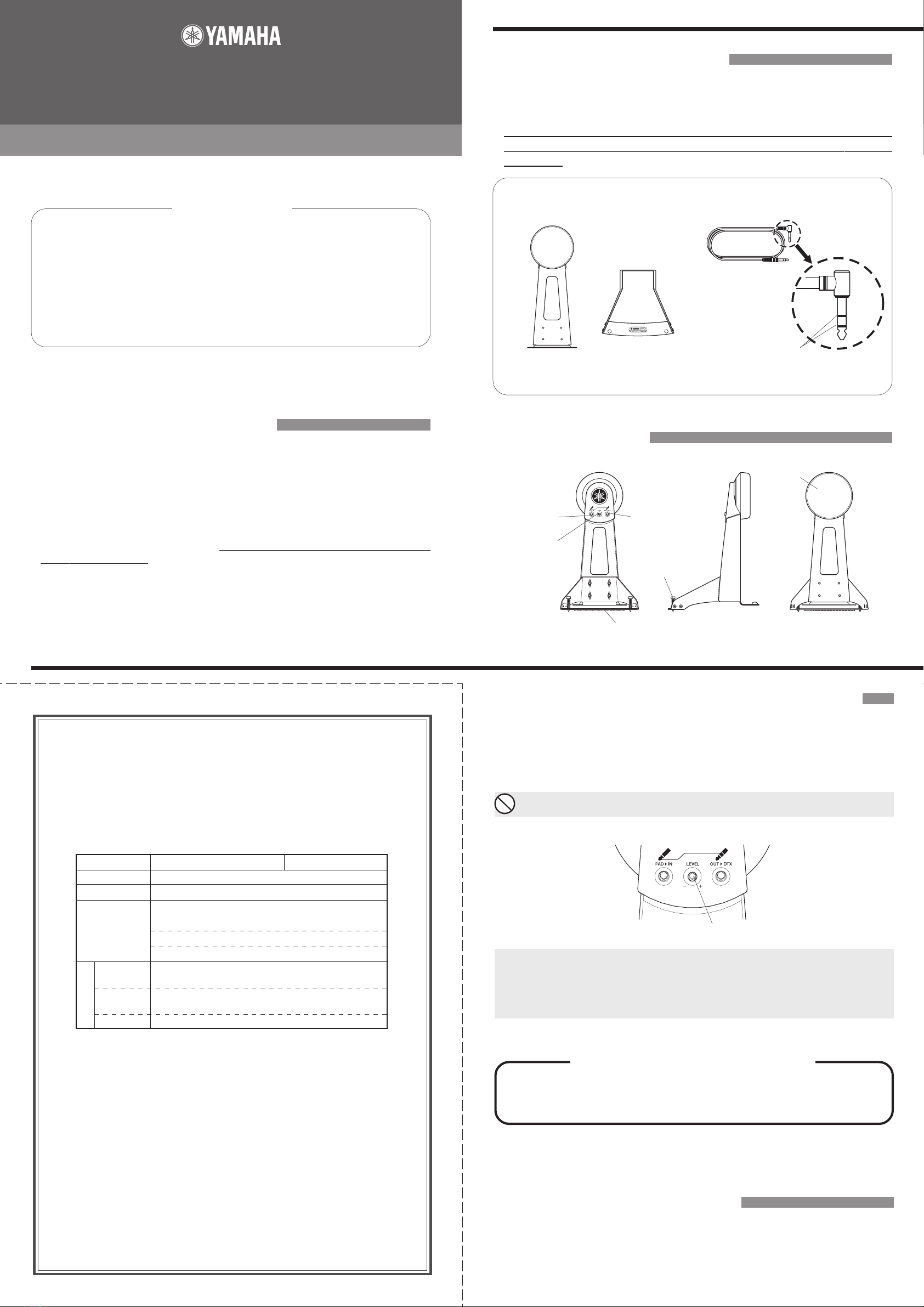
■Connections
Use the supplied stereo phone cable to
connect the KP65's output jack to an
input such as the KICK jack, etc., on
the DTX Series Drum Trigger Module
(DTXPRESS/DTX/DTXTREME).
Connect the cable's L-shaped plug to
the pad.
Base
Main
Body
Washer
Spring
Washer
Wing Bolt
DTXPRESS
DTX
DTXTREME
Beater
Beater Beater
(Double Foot Pedal)
Stereo Phone Cable (supplied)
NOTE:
When the KP65 is used with a DTX Series Drum Trigger Module, set the pad type that is assigned
to the INPUT to which the KP65 is connected, to kick pad.Trouble such as double triggers (multiple
triggers produced by a single stroke on the pad), etc. may result if the parameter is set to any other
pad type. Please refer to the Owner's Manual that came with your module for more information.
NOTE: When the KP65 is used without an external pad connected to the KP65, a monaural phone cable
(Plug has one black rings) may be used.
❇The DTX Series Drum Trigger Module's Self-Rejection function can also be used to control double triggers when the
problem can not be solved with any of the solutions provided above. Please refer to the Owner's Manual that came with
your module.
●Connecting an External Pad
The KP65's external pad input jack can be used to send two trigger signals, one from
the KP65 and another from an external pad connected to the KP65, to the DTX Series
Drum Trigger Module via a single stereo cable (supplied).
NOTE: When using the KP65 with an external pad, make sure the following inputs on the DTX Series
Drum Trigger Module are used. [DTXPRESS: 9/10, DTX: 9/10, 11/12, DTXTREME: 9/10-15/16]
NOTE: Either a stereo or monaural cable can be used to connect the external pad to the KP65.
NOTE: Any pad that is designed for use with the DTX Series Drum Trigger Modules can be used as an
external pad however, the sound produced by the rim (edge) will not be produced when a pad
equipped with a rim (edge) switch (or rim trigger sensor) (TP65S, PCY65S, RHP Series, etc.)is
connected to the KP65. In this case, the rim (edge) switch functions (choke, mute) can not be
used.
DTXPRESS
DTX
DTXTREME
TP65 PCY65
PCY10etc.
Stereo Phone Cable (supplied)
Printed in Indonesia
WF75910
■Troubleshooting
If the following trouble occurs when the KP65 is used, please check the following points
before asking your dealer for assistance.
Is the KP65's LEVEL Adjustment
Knob set too high?
●
Double Trigger (multiple triggers produced by a single stroke on the pad)
What to check
Problem
When the LEVEL Adjustment Knob is set too high, a large signal
sustained for a period of time, which causes the Module to produce
multiple sounds. Refer to the previously described “Output Level
Adjustment” section and adjust the level to an optimum level.
Is the DTX Series Drum Trigger
Module's Pad Type parameter for
the INPUT jack to which the KP65
is connected, set to a type other
than Kick Pad?
If the Pad Type parameter is set to anything other than Kick
Pad, double triggers may easily occur even though signal
strength may be the same. Please refer to the Owner's Manual
that came with your drum trigger module for more information.
●No sound, volume is low
What to check
Problem
Is the KP65 properly connected
to the DTX Series Drum Trigger
Module's INPUT jack using the
supplied stereo phone cable?
Refer to the previous “Connections” section and make sure
that all connections are proper.
Is the KP65's LEVEL Adjustment
Knob set too low?
If the LEVEL Adjustment Knob is set too low, the signal
produced by the pad will be too low to produce sufficient
volume from the module's tone generator even though the pad is struck.
I
s the module properly connected to
a pair of headphones or an external
audio device such as an amplifier,
speaker, etc.?
Check the connections between the external audio device and
the drum trigger module, the power switch on the external de-
vice, and the volume level.
Are module settings correct? Check the volume setting of the voice assigned to the INPUT
to which the KP65 is connected (refer to the previous “Adjust-
ing the Voice Volume” section) or that the volume level for the
headphones is not set too low.
Is a hi-hat control pedal (HH65,
etc.) assigned for use as a kick
pad in the module's (DTXPRESS)
settings?
Settings in the DTXPRESS allow a hi-hat control pedal (HH65,
etc.) connected to the INPUT 1 (KICK) jack to be used as a
kick pedal. However, if the setting hasn't been changed, the
KP65 can not be used when connected to the INPUT 1 (KICK)
jack. To reset the setting, please refer to the Owner's Manual
that came with your DTXPRESS.
Also refer to the Owner's Manual that came with your DTX Series Drum Trigger Module (DTXPRESS/DTX/
DTXTREME), in regards to the problems described above and any other problems that you may be experi-
encing.
After consulting the manuals a solution can not be found to the problem, please contact the dealer from
whom you purchased the product.
■Specifications
Size 233(W) x 271(D) x 416(H) mm (When Assembled)
Weigh 2.7kg
Sensor System Tr igger Sensor (Piezo) x 1
Input Jack Standard Monaural Phone Jack
Output Jack Standard Stereo Phone Jack
* Improvements may result in a change in the specifications and/or design of the product without notice.
SPECIAL MESSAGE SECTION
NOTICE: Service charges incurred due to a lack of knowledge relathing to how a function or effect works (when the unit is operating
as designed) are not covered by the manufacturer’s warranty, and are therefore the owners responsibility. Please study this manual
carefuly and consult your dealer before requesting service.
ENVIRONMENTAL ISSUES: Yamaha strives to produce products that are both user safe and environmentally friendly. We sincerely
believe that our products and the production methods used to produce them, meet these goals. In keeping with both the letter and the
spirit of the law, we want you to be aware of the following:
Warning: Do not attempt to disassemble.
Disposal Notice: Should this product become damaged beyond repair, or for some reason its useful life is considered to be at an end,
please observe all local, state, and federal regulations that relate to the disposal of products that contain lead, plastics, etc. If your
dealer is unable to assist you, please contact Yamaha directly.
NAME PLATE LOCATIOIN: The name plate is located on the bottom of the product. The model number, serial number are located on
this plate.
You should record the model number, serial number, and the date of purchase in the spaces provided below and retain this manual as
a permanent record of your purchase.
Model : KP65 Serial No.
Purchase Date
PLEASE KEEP THIS MANUAL