Somati system s.r.o., Jihlavská 510/2c, 664 41 Troubsko
ID: 29260159, Tax ID: CZ29260159
www.somati-system.cz
List of documentation:
1WIRING EXAMPLE............................................................................................ 1
2MECHANICAL INSTALLATION .......................................................................... 2
3ELECTRICAL WIRING ....................................................................................... 3
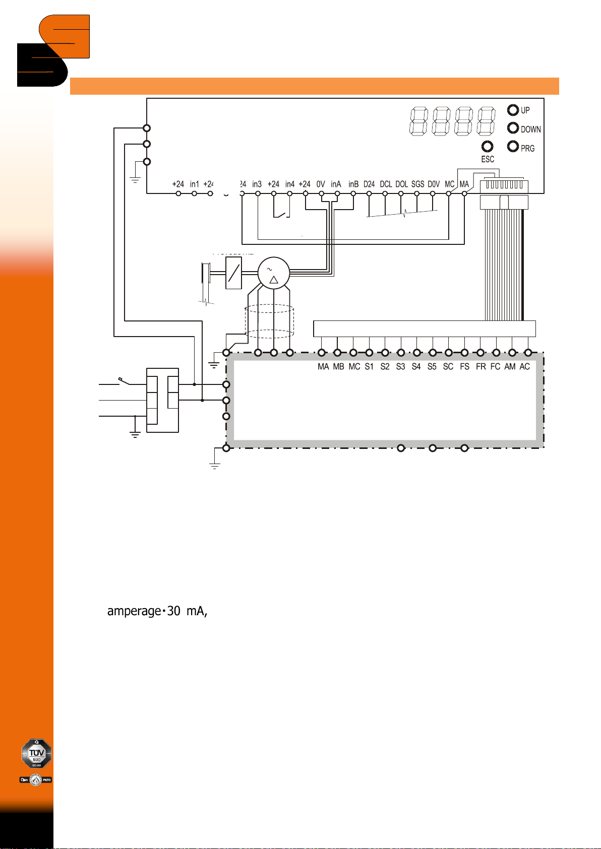
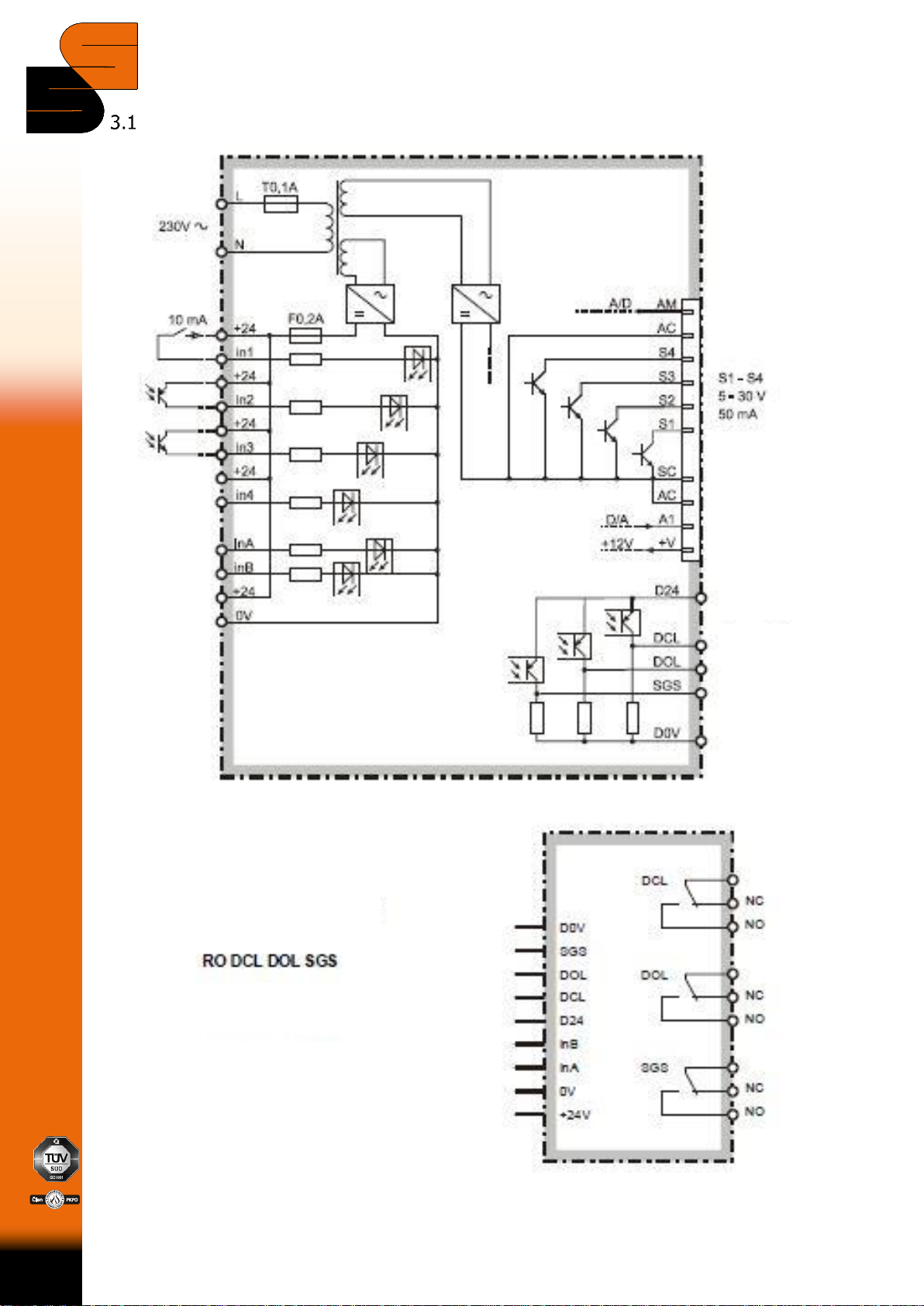
3.1 Input/output connection diagram of VJ002v........................................................ 4
4REFERENCE SEARCHING .................................................................................. 5
4.1 Motor phase conductors matching ...................................................................... 5
4.2 Reference searching without limit switch............................................................. 5
4.4 Reference searching via limit switch ................................................................... 6
5OPENING .......................................................................................................... 6
6CLOSING........................................................................................................... 8
7OVERLOAD EVALUATION ...............................................................................10
7.1 Evaluation by speed difference......................................................................... 10
7.2 Evaluation by current excess ............................................................................ 10
8PUSHING IN END POSITIONS........................................................................ 11
9END POSITIONS REGULATION ...................................................................... 11
10 SIGNALS TO DOOR CONTROL SYSTEM ........................................................ 11
11 IMPORTANT CONTROL AND DSETTINGS INVERTER COMPONENTS AND
CONSTANTS....................................................................................................13
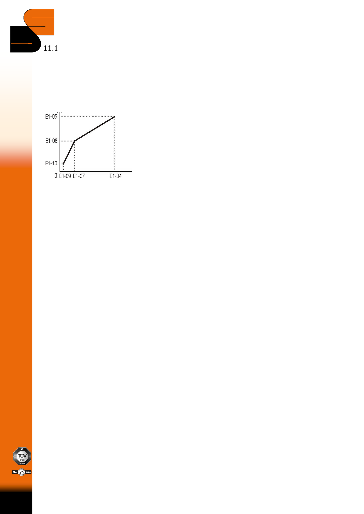
11.1 V/f pattern .................................................................................................. 15
11.2 Ramps and S-curve pattern.......................................................................... 16
11.3 Programmable inputs S3, S4 ........................................................................ 16
11.4 Over-torque detection.................................................................................. 16
11.5 Overload detection - IOL.............................................................................. 16
11.6 Fault Diagnoses........................................................................................... 17
12 SET 1RM1 ..................................................................................................... 18
13 PROGRAMMABLE RELAY ZEN .......................................................................23
14 PERIODICAL INSPECTIONS .........................................................................25
14.1 Inverter ...................................................................................................... 25
14.2 Cabinet ....................................................................................................... 25
14.3 UPS –required user maintenance................................................................. 25
15 CIRCUMFERENTIAL SCHEMATICS................................................................ 26
15.1 Power supply .............................................................................................. 26
15.2 Power unit .................................................................................................. 27
15.3 Frequency converter circuit .......................................................................... 28
15.4 Door unit .................................................................................................... 29
15.5 Programmable relay .................................................................................... 30
15.6 Controls ...................................................................................................... 31
15.7 Photocell, flashlight (signalization)................................................................ 32
15.8 Signalization of door status .......................................................................... 33
15.9 Cabling 1 .................................................................................................... 34
15.10 Cabling 2 .................................................................................................... 35
15.11 Cabling 3 .................................................................................................... 36
15.12 Sensor connection for the drive 1RM1........................................................... 37