SOMFY LIGHTING OUTDOOR RTS User manual

Infrared Heater RTS
1. INTRODUCTION
2. SPECIFIC SAFETY REQUIREMENTS
2.1 SAFETY AND RESPONSIBILITY
RISK OF FIRE
2.2 MANDATORY SAFETY REQUIREMENTS
3. INSTALLATION
4. MOUNTING
4.1 MOUNTING W/ WALL BRACKET
4.2 MOUNTING W/ AWNING BRACKET
5. PROGRAMMING RTS RECEIVER
5.1 PROGRAMMING THE RTS REMOTE TO RECEIVER
5.2 ADDING RTS REMOTE TO MEMORY OF THE RECEIVER
5.3 REMOVING AN RTS REMOTE FROM THE MEMORY OF THE RECEIVER
5.4 TO RESET
6. OPERATING INFRARED HEATER
7. TECHNICAL DATA
TROUBLESHOOTING
8. MAINTENANCE
9. WARRANTY
P 1
P 1
P 2
P 2
P 2/4
P 4
P 5
P 6-7
P 7-8
P 8
P 8
P 9
P 9
P 10
P 10
P 11
P 12
P 12-17
P 17
TABLE OF CONTENTS

1. INTRODUCTION
The Infrared Heater RTS is 120V 60Hz 12.5amps. It produces radiant
heat like the sun, warming people and objects rather than the air in
between. It is mounted on an adjustable bracket that allows the heat
to be directed exactly where it is required. The Infrared Heater RTS is
designed for indoor and outdoor use so is therefore weatherproof.
NOTE: PLEASE READ THE FOLLOWING INSTRUCTIONS CAREFULLY BEFORE USE. THE SAFETY OF THIS
HEATER IS GUARANTEED ONLY BY ITS CORRECT USAGE IN ACCORDANCE WITH THESE INSTRUCTIONS,
THEREFORE IT IS RECOMMENDED THAT THEY ARE RETAINED FOR FUTURE REFERENCE.
2. SPECIFIC SAFETY RECOMMENDATIONS
Read all instructions before using this heater.
This heater is hot when in use. To avoid burns, do not let bare skin touch
hot surfaces. If provided, use handles when moving this heater. Keep
combustible materials, such as furniture, pillows, bedding, papers, clothes,
and curtains at least 6FT from the front of the heater and keep them away
from the sides and rear. Extreme caution is necessary when any heater is
used by or near children or persons with disabilities and whenever the
heater is left operating and unattended.
P1.

WARNING: RISK OF FIRE
KEEP COMBUSTIBLE MATERIALS SUCH AS FURNITURE, PAPERS,
CLOTHES AND CURTAINS AT LEAST 6 FEET (1.8M)FROM THE FRONT
OF THE HEATER AND AWAY FROM THE SIDES AND REAR. 1.8m
(6ft)
2.2 MANDATORY SAFETY REQUIREMENTS
___ Use this heater only as described in this manual. Any other use not
recommended by the manufacturer may cause fire, electric shock, or injury
to persons.
___Do not install less than the 7 feet from the foor .
___Warning - this appliance must be grounded! (A)
___To prevent a possible fire, do not cover or obstruct
the heater at any time (awning fabric/front valance).
___Do not locate the heater immediately below a outlet.
___Ensure that the heater has been securely fastened in its final mounting
position before using.
P2.
2.1 SAFETY AND RESPONSIBILITY
IMPORTANT INSTRUCTIONS
When using electrical appliances, basic precautions should always be
followed to reduce the risk of fire, electric shock, and injury to persons,
including the following:

P3.
(b)
___Unplug the heater during installation, cleaning and/or
replacing the light bulb, always ensure that the light bulb
is cool.
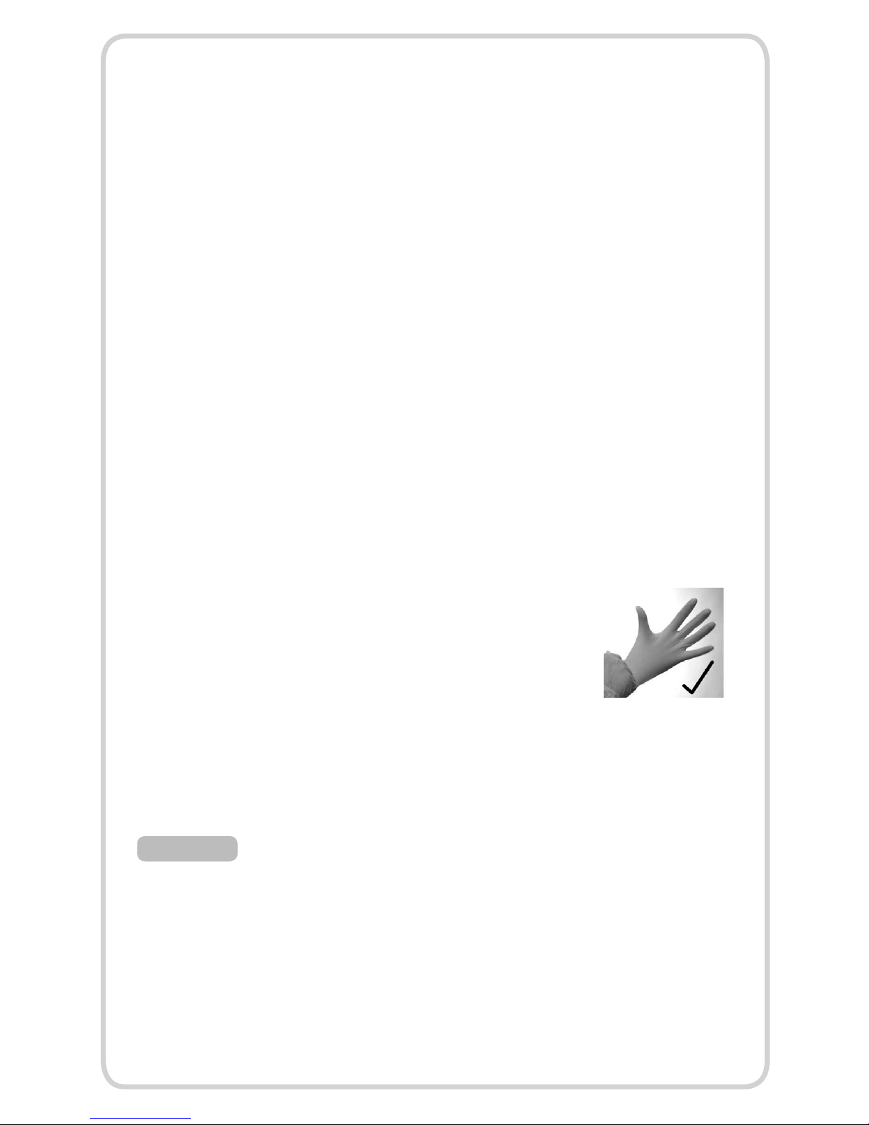
___Do not handle the halogen light bulb with bare hands. (B)
___If the light bulb (light bulb) is inadvertently touched,
remove finger marks with a soft cloth and methylated spirit or
alcohol. Otherwise, the marks will burn into the quartz light
bulb causing premature heater failure.
___Do not use an extension cable with this product.
___Keep the power cable away from the body of the heater which will get
hot during use.
___The heater is not intended for use by young children or persons with
disabilities unless they have been adequately supervised by a responsible
person to ensure that they can use the heater safely.
___Do not use if front grill is damaged or missing.
___ Always unplug heater when not in use.
___ To disconnect heater remove plug from outlet.
___ Do not operate any heater with a damaged cord or plug or after the
heater malfunctions, has been dropped or damaged in any manner. Return
heater to authorized service facility for examination, electrical or mechanical
adjustment, or repair.
___ This heater is not intended for use in bathrooms, laundry areas and
similar locations. Never locate heater where it may fall into a bathtub or other
water container.

___ Do not run cord under carpeting. Do not cover cord with throw rugs,
runners, or the like. Arrange cord away from traffc area and where it will not
be tripped over.
___ Do not insert or allow foreign objects to enter any opening as this may cause
an electric shock or fire, or damage the heater.
___ A heater has hot parts inside. Do not use it in areas where gasoline, paint, or
fammable liquids are used or stored.
___ Keep out of the reach of children.
3. INSTALLATION
The Infrared Heater RTS is ftted with 16’ 5” (5 meters) of supply cable
and a molded plug.
If the supply cord is damaged, do not use.
When the electrical connection is outside, (while in use) it is recommended
that a waterproof outlet, is used for the connection. Otherwise, the plug
should be connected to an indoor grounded outlet.
If in any doubt, please contact a licensed electrician. The infrared heater
provides heat up to 130 sq ft. (13x10) approx. equivalent to a table with
fve chairs.
P4.

P5.
4. MOUNTING
The heater should always be angled
downwards when mounted as shown.
Always allow the heater to cool before
attempting to reposition/move. Never
attempt to move the heater while it is
switched on.
(a)
Ensure the minimum safe distance between the heater body and
infammable surfaces and objects when mounting refer to table below
and drawing (a).
MIN. DISTANCE
FROM AWNING
MIN. DISTANCE
FROM SIDE
WALL
DIMENSIONS
W X H X D
WEIGHT
(LBS)
ENVIRONMENTAL
RATING
MINIMUM
DISTANCE
FROM
GRILL
MIN. DISTANCE
FROM FLOOR
1fT 3 1/2fT 22” x 4
½” x 6
1/4’
6.2 Ip24 6fT 7fT
AND/OR CEILING

P6.
Step One
Step Two
4.1 MOUNTING WITH WALL BRACKET (ATTACHED TO THE HEATER)
ENSURE THAT VALANCE OF THE AWNING DOES NOT OBSTRUCT WITH
HEATER WHEN RETRACTED. REFER TO DRAWINGS BELOW.
Securely fasten the Infrared Heater RTS
(1) to the wall using the fxing holes in
the wall bracket (3). Securely fasten the
RTS heat receiver bracket (2) to the wall
bracket.
Rotate the heater to the required angled position and tighten
the fxing bolt located on the bracket at the rear of the heater.
3.
P7.
Step Three
Secure the supply cable local to the Infrared Heater RTS
so the cable is directed away from the heater and is not resting
on the body or obstructing the air-vents.
noTe: always unplug the heater when adjusting the angled position.
Step One
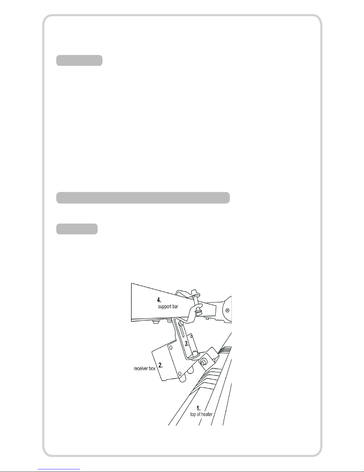
4.2 MOUNTING WITH AWNING BRACKET (OPTIONAL)
Securely fasten the Infrared Heater RTS (1) with the awning mounting
bracket (3) (optional) to the square bar (4) of the awning using the fxing
holes in the bracket.
Step Two
Step Three
P8.
programming button
(1)
(2)
Rotate the heater to the required angled position and tighten the fxing
bolt located on the bracket at the rear of the heater.
Secure the supply cable local to the Infrared Heater RTS using a ‘P’ clip
(supplied) so the cable is directed away from the heater and is not resting
on the body or obstructing the air-vents.
noTe: always unplug the heater when adjusting the angled position.
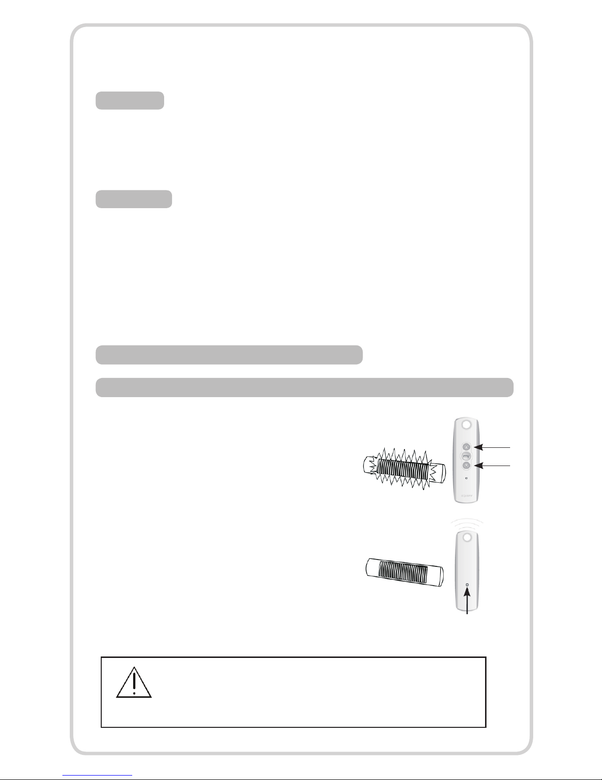
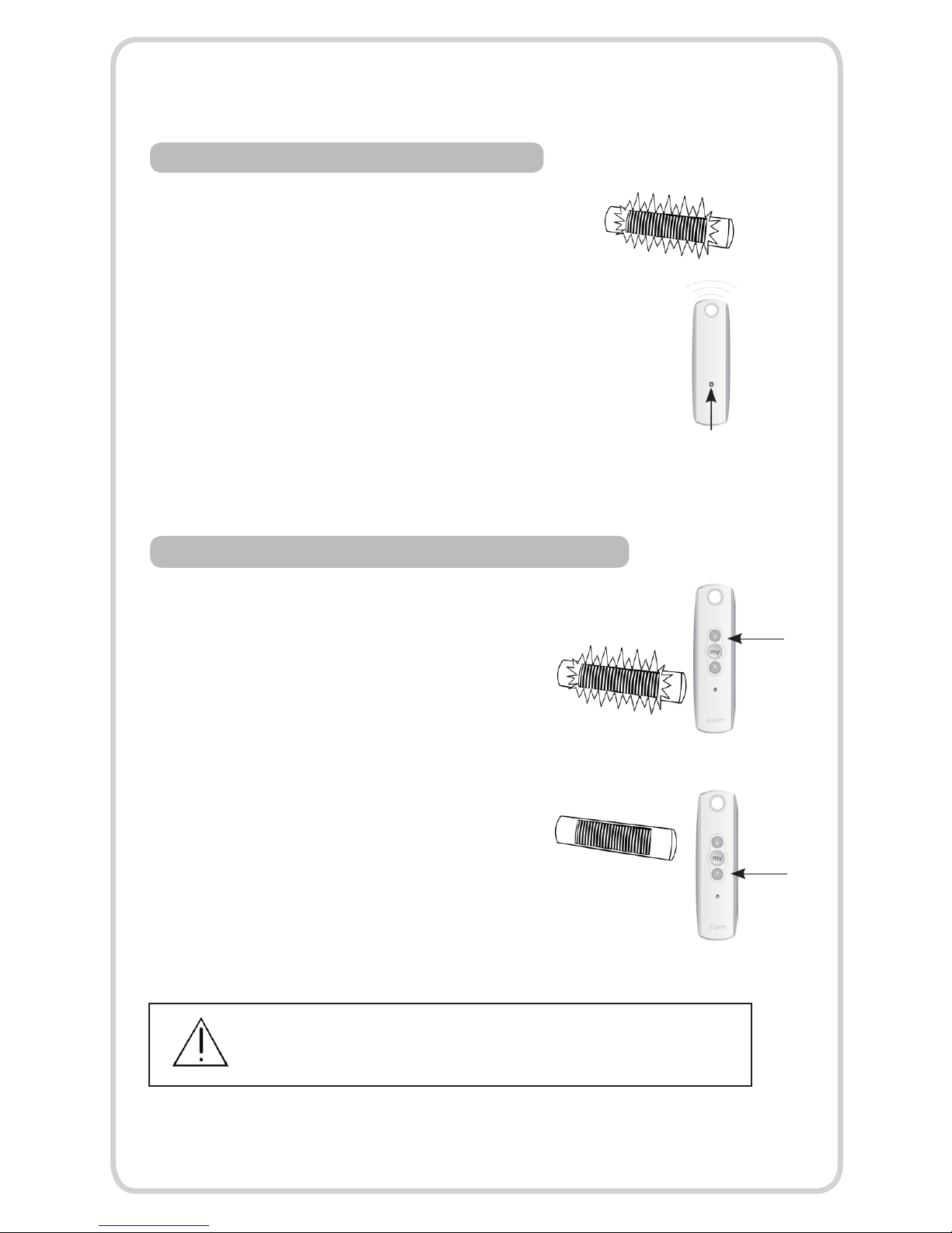
5. PROGRAMMING THE RTS RECEIVER
5.1 PROGRAMMING THE REMOTE TO THE MEMORY OF THE INFRARED HEATER RTS RECEIVER
To add the first transmitter to the memory
of the receiver, press the Up and Down buttons
on the RTS transmitter (1) simultaneously until
the heater lights up then turns off. Press the
programming button on the new transmitter
(2) to add it to the receiver. The heater will light
up/turn off indicating it has been properly
programmed.
WARNING : DO NOT RECORD THE HEATER RECEIVER ON THE SAME CHANNEL
AS THE AWNING MOTOR BUT MAKE SURE IT IS PROGRAMMED ON A SEPARATE
AND DEDICATED RTS TRANSMITTER CHANNEL. (REFER TO RTS REMOTE CONTROL
INSTRUCTIONS FOR CHANNEL SELECTION)
P9.
programming button
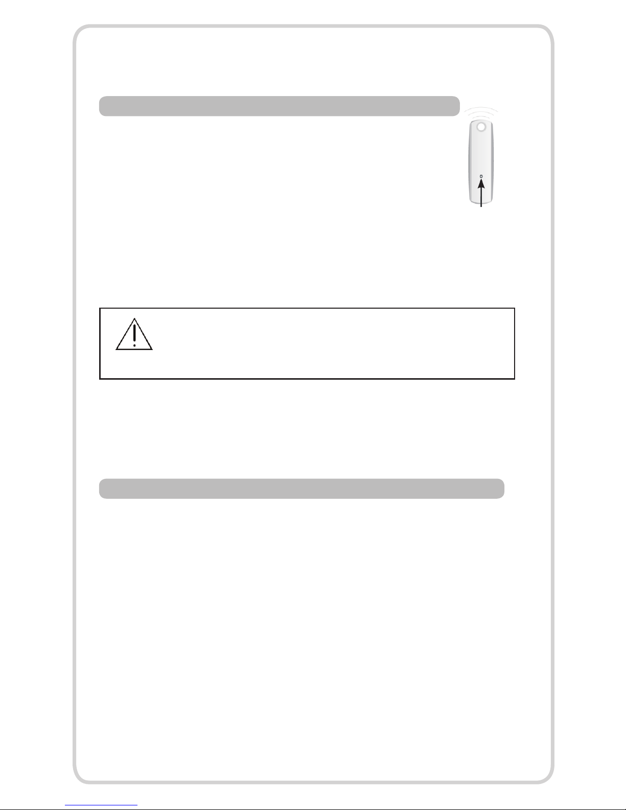
5.2 ADDING AN RTS REMOTE TO THE MEMORY OF THE RECEIVER
WARNING : DO NOT RECORD THE HEATER RECEIVER ON THE SAME CHANNEL
AS THE AWNING MOTOR BUT MAKE SURE IT IS PROGRAMMED ON A SEPARATE
AND DEDICATED RTS TRANSMITTER CHANNEL. (REFER TO RTS REMOTE CONTROL
5.3 REMOVING AN RTS REMOTE FROM THE MEMORY OF THE RECEIVER
First press the programming button on the back of the already
programmed remote until the heater lights up. Then press the
programming button on the remote that you would like to erase
until the heater lights up, then turns off, indicating it has been
properly removed from the memory of the receiver. Check it.
First press the programming button on the back of the
already programmed remote until the heater lights up,
Then press the programming button on the remote that
you would like to add until the heater lights up, then
turns off, indicating it has been properly programmed.
Check it.
then turns off.
INSTRUCTIONS FOR CHANNEL SELECTION)
P10.
programming button
5.4 TO RESET THE MEMORY OF THE RECEIVER
You will need to disconnect power for 2 seconds,
reconnect for 10 seconds, disconnect for another
2 seconds and reconnect. The light should turn
on (if this does not happen, continue to perform
the disconnects until it does). Once the light comes
on it’s own, press and hold the programming
button on the back of the remote and count to
ten without letting go. The heater should blink
twice indicating the memory of the receiver has
been reset.
6. OPERATING THE INFRARED HEATER RTS
To switch on the Infrared Heater RTS press the UP
button of the transmitter.
To switch off the Infrared Heater RTS press
the DOWN button of the transmitter.
on
off
ENSURE YOU TURN THE HEATER OFF WHEN UNATTENDED OR AWNING
IS RETRACTED/CLOSED.
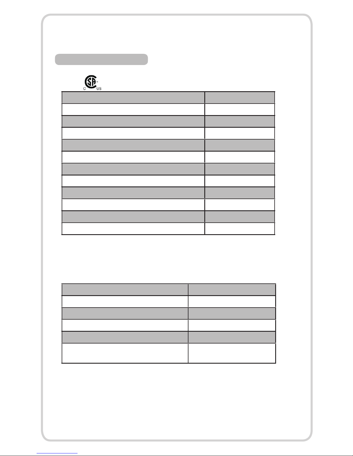
Radio frequency 433.42 MHz
Power supply 120 V/60 Hz
Environmental rating IP 67
Operating temperate -20 C to + 70 C
Product category II
Number of RTS control points programmable for
one infrared heater RTS
12 maximum
Voltage 120V
Power W 1500
Current (A) 12.5
Minimum mounting height from the foor 7FT
Minimum distance from the ceiling and/or awning 1FT
Minimum from side wall (inches) 3.5FT
Weight (LBS) 7
Insulation Class I
Environmental rating IP 24
Dimensions W x H x D (inches) 22 x 4.4 x 6.3
PHILLIPS lamp life (hours) 5000 - 7000
Heat Span (Sq Feet) / coverage 130
HEATER RTS RECEIVER
HEATER
P11.
7. TECHNICAL DATA

Pressing a
button on the
control point
has no effect
on the heater.
The heater is not plugged in. Plug in the heater
The power supply is faulty . Contact licensed electrician.
The batteries in the control
point are weak.
Replace the batteries, using
the same battery model.
The heating lamp is blown Replace the heating lamp(s)
The control point has not
been programmed into
the RTS Receiver
Follow the procedure for add-
ing an RTS control point - see
section entitled “Adding RTS
control points”.
Radio interference prevents the
operation of the RTS transmitter
and RTS.
Turn off any radio equipment
nearby.
TROUBLESHOOTING
P12.
8. MAINTENANCE
In the event of heater failure, or for spare parts or advice, please contact
your distributor in the first instance.
Disconnect from the power supply before attempting any maintenance
procedure including cleaning.
To ensure optimum heat effectiveness, it is recommended that the guard and
light bulb are removed and the refector is wiped with a lint-free cloth before
reassembling should the refector show considerable signs of dust or dirt.
Your Replacement Light Bulb
It is very important that your replacement light bulb is exactly the same as
the one it was supplied with. Failure to fit the exact same type could cause
the heater to fail or even become dangerous especially when used in an
outdoor environment.
Please contact your distributor to purchase your replacement light bulb and
state the model number of the heater you wish to ft the light bulb to.
Handling The Replacement Light Bulb
Your new light bulb should not be handled with bare hands. Remove finger
marks with a soft cloth and methylated spirits or alcohol. Finger marks will
burn into quartz causing premature light bulb failure.
Replacing The Light Bulb
If you are in any doubt about following the procedure
below, please contact your distributor. The main power
should be disconnected before any attempts are made
to replace the light bulb.
Ensure the heater light bulb is cool and the power supply is disconnected
by removing the plug(s) from the outlet.
Step One
P13.
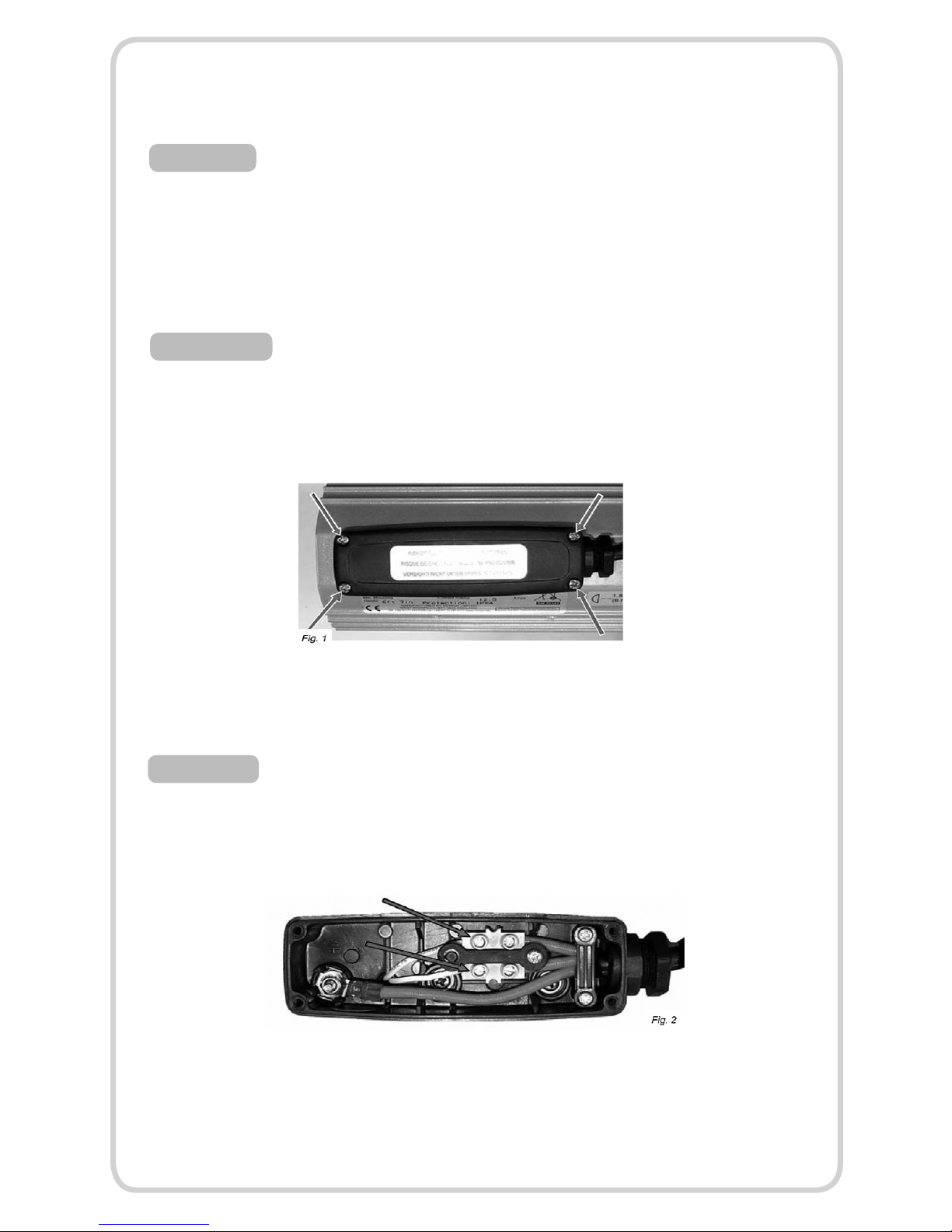
Remove the heater from its mounting and work on a safe, flat
surface.
Remove the screws from the terminal box (Fig. 1) and lift off the cover.
Disconnect the light bulb from the connector blocks by unscrewing the screws
highlighted above in Fig. 2.
Step Two
Step Three
Step Four
P14.

Step Five
Step Six
Step Seven
Unscrew the four screws
(see Fig. 3) from the end cap
and remove from the heater
body. Repeat at opposite end.
Slide out the side covers from
both ends and slide out the
guard either end.
Firstly remove the two screws
as highlighted in Fig. 5 to
remove the side refector.
P15.

Step Eight
Step Nine
Step Ten
Starting at the end where the
light bulb wires are fed through
the gasket into the terminal
box, gently pull the light bulb
wires through the body of the
heater so the wires exit the
terminal box (Fig 6).
At the opposite end of the
heater, gently pull the light bulb
wire out of the tube as shown
in Fig. 7.
Feed the light bulb wires through
the side refector brackets so
they are free of the brackets and
then one at a time pull the spring
clips back and lift up the ceramic
caps of the light bulb to remove it
P16.
The light bulb should now be removed from the heater. Reft the new light
bulb in reverse order ensuring the ceramic caps are correctly seated in the
aluminum light bulb holders, no wires are trapped and all screws are fully
tightened.
disposal of product:
By ensuring this product is disposed of correctly, you
will help prevent potential negative consequences for
the environment and human health, which could
otherwise be caused by inappropriate waste handling
of this product.
Step Eleven
9. TWO YEAR WARRANTY ON FIXTURE
This product is warranted to be free of defects in workmanship and materials
for a period of 2 years from the original date of production. If any problems
appear (other than burnt out bulbs, which carry no warranty) within 2 years,
the purchaser may return the item, freight prepaid, together with a copy of
your original purchase receipt to your distributor. This warranty does not cover
fxtures that have been altered in any way or fxtures that have been subject to
misuse, accidents or damage in transit.
IN NO CASE SHALL THE COMPANY BE LIABLE FOR ANY INCIDENTAL OR CONSEQUENTIAL DAMAGES.
NO CHARGES WILL BE ACCEPTABLE FOR UNAUTHORIZED REPAIRS, PARTS OR SERVICE.
NOTE: DOES NOT APPLY TO BULBS WHICH HAVE NO WARRANTY
P17.
Somfy Systems, Inc.
47 Commerce Drive
Cranbury, NJ 08512
Somfy Florida
6100 Broken Sound Pkway, N.W. Suite 14
Boca Raton, FL 33487
Somfy California
15291 Barranca Pkwy
Irvine, CA 92618
Somfy Canada
6315 Shawson Drive Unit #1
Mississauga, Ontario L5T1J2
© Somfy Systems, Inc. 3/2009
Other manuals for LIGHTING OUTDOOR RTS
5
Table of contents
Popular Heater manuals by other brands


EVEREADY
EVEREADY RH1000 user manual

HeatStar
HeatStar HS35LP operating instructions

NORDIC HEAT
NORDIC HEAT Heat Seat user manual

Roberts Gorden
Roberts Gorden Vantage TF-Series Installation & operation

CaptiveAire
CaptiveAire D76 Installation, operation and maintenance manual

EOS
EOS 34.G HD Assembly and operating instruction


