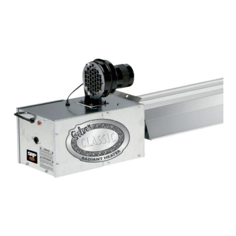
SRP BIG SHOT User manual

SRP BIG SHOT® Page 1 LT218 4/9/2019
Assembly Instructions
INFRARED HEATER
WARNING
FOR YOUR SAFETY
Improper installation, adjustment, alteration, service or
maintenance can cause property damage, injury or
death. Read the installation, operating and maintenance
instructions thoroughly before installing or servicing this
equipment.
Do not store or use gasoline or other flammable vapors and
liquids in the vicinity of this or any other appliance.
If you smell gas:
1. Open windows
2. Don’t touch electrical switches
3. Extinguish any open flame
4. Immediately call your gas supplier
OWNER
INSTALLER
Retain this Manual & ensure available for service.
Improper installation, adjustment, alteration, service or
maintenance can cause injury, death or property
damage. Read the installation, operation and service
instructions thoroughly before installing or servicing this
equipment
Provide Manual to Owner upon completion of installation!
Read and thoroughly understand these Instructions before
attempting any installation
SRP BIG SHOT®
RADIANT AGRICULTURAL HEATER
WIDE HEAT DISTRIBUTION
Canada: 563 Barton Street, Stoney Creek, Ontario L8E 5S1
USA: 315 N Madison Street, Fortville, IN 46040
www.superiorradiant.com

SRP BIG SHOT® Page 2 LT218 4/9/2019
CAUTION: FIRE OR EXPLOSION HAZARD
Maintain clearance to combustible constructions as further specified in this manual. Failure to do so
could result in a serious fire hazard. Heaters should not be located in hazardous atmospheres
containing flammable vapors or combustible dusts. Signs should be provided in storage areas
specifying maximum safe stacking height.
CAUTION: MECHANICAL HAZARD
This equipment expands and contracts with each operating cycle. The gas connection, suspension
hardware and the installation itself must safely allow this movement. Failure to do so could result in
serious fire or explosion hazard.
CAUTION: FIRE OR EXPLOSION HAZARD
This heater is equipped with an automatic ignition device. Do not attempt to light the burner by
hand. Failure to comply could result in a serious fire and personal injury hazard.
CAUTION: MECHANICAL HAZARD
Do not use high pressure (above 1/2 psi) to test the gas supply system with the burners connected.
Failure to do so could result in damage to the burner and its control components requiring
replacement.
CAUTION: SERVICE LIFE RISK
Do not install equipment in atmospheres containing halogenated hydrocarbons or other corrosive
chemicals. Failure to do so may lead to premature equipment failure and invalidation of the
warranty. Additionally, it is recommended that the equipment be installed with a slope downward
and away from the burner of ¼" (6mm) in 10' (3m) to allow start-up condensate drainage.

SRP BIG SHOT® Page 3 LT218 4/9/2019
Hang these about 100” apart.
Install Tubes and U-Bolts.
Step 1:
Step 2-A:
Step 2-B:
U-Bolt with extra nuts –close to Flange. The nuts sandwich the Hanger Bracket as pictured above.
Before installing the four U-Bolts, just ONE of the U-Bolts gets extra nuts, as shown here:
100”
Thread the extra nuts upwards
(they don’t need to be tight for now)

SRP BIG SHOT® Page 4 LT218 4/9/2019
On the burner side, the distance between
the Flange and U-Bolt should be 9”
On the U-Tube side, the distance between
the Tube’s end and U-Bolt should be 10”
Fasten the remaining 8 nuts onto the U-Bolts –leave these loose until the end!
Step 3:
Step 4:
Orient the Tubes within the U-Bolts.
9”
10”

SRP BIG SHOT® Page 5 LT218 4/9/2019
Install the Baffles: Pictured below is a bottom view of the heater.
2 foot Baffle is isolated in the Flanged Tube (Combustion Tube)
6 foot and 4 foot Baffle are linked together in the Non-Flanged Tube (Return Tube)
Step 5:
2 foot Baffle
(Big Shot 80 only)
4 foot Baffle
(Big Shot 80 only)
6 foot Baffle
(Big Shot 60 and 80)
Bend Baffle Tab
over edge of Tube
at 6:00 position
Lock both Baffles together before inserting:
Align the little tabs and keyhole together at a 90 degree angle. Insert the tabs into the keyhole.
Rotate to 0 degrees, and then slide both Baffles into the Non-Flanged Tube.
Bend Baffle Tab
over edge of Tube
at 6:00 position

SRP BIG SHOT® Page 6 LT218 4/9/2019
Step 6:
The Coupling has a tab inside to dictate the depth of the Tubes and U-Tubes.
Both edges of the Tube and U-Tube should be touching.
Attach Couplings and U-Tube together.
Step 7:
Place Reflectors onto heater.
They’ll be loose for now, but these two pictures depict how
the Reflectors will be oriented once they are fastened:

SRP BIG SHOT® Page 7 LT218 4/9/2019
Step 8-A:
Install the following components, 62” (middle)
from the edge of the Reflector:
Qty 2 - CR004 Reflector Brackets
Qty 2 - CR009 Spring Clip
Qty 4 - CH044 Screw, 8-32 x 1-1/4
Hex Head, Roberston #2
62”
Step 8-B:
Set the screws to a leave a gap of no more than 0.125”

SRP BIG SHOT® Page 8 LT218 4/9/2019
Step 9:
Install the Inner End Cap with 6 screws,
as pictured here:
End Cap with flanges on the inside (hidden).

SRP BIG SHOT® Page 9 LT218 4/9/2019
Step 10:
Fasten one Hanger to the Reflector,
using the standard screws.
Secondly, hold the Reflector tight to the bracket while fastening.
Screw the bracket to the reflector.
Firstly, ensure the Hanger Bracket is
perpendicular to the Reflector, and
then follow these dimensions:
Fasten this
bracket only.
(This bracket is left free
for reflector expansion)
6”
3”
Step 10-A:
Step 10-B:
Match the profile of the Reflector and Bracket as pictured:

SRP BIG SHOT® Page 10 LT218 4/9/2019
Step 11-A:
Orient the End Caps onto the Reflector.
Step 11-B:
Fasten the End Caps with a total of 12
standard screws.
End Cap with flanges on the outside

SRP BIG SHOT® Page 11 LT218 4/9/2019
Step 12:
Fasten the Hanger to the Reflector, using the standard screws.
*While fastening, hold the Reflector tight to the bracket.

SRP BIG SHOT® Page 12 LT218 4/9/2019
Step 13-A:
Attach the U-Tube End Cap to the
U-Tube Reflector with 10 screws,
as pictured here:
Step 13-B:
Install the Reflector onto the heater by
overlapping the two reflectors.
*Critical!
Before fastening in the next step, ensure that there is a 2” gap
between the U-Tube and End Cap.
There should an overlap of about 9”, but the 2” space
mentioned above is the driving dimension!
2”
End Cap with flanges on the outside.

SRP BIG SHOT® Page 13 LT218 4/9/2019
To fasten the Reflector, use standard screws as shown:
Step 14:

SRP BIG SHOT® Page 14 LT218 4/9/2019
To fasten the Tubes down, tighten all U-Bolt Nuts to be snug.
The only unique case pertains to the 4 nuts on the U-Bolt close to the flange.
Step 15:
These 6 nuts are to be snug.
Tighten these nuts to lock the U-Bolt in
place, leaving the Tube loose.
Don’t secure the Tube down, as it
needs to move freely during heating
and expansion

SRP BIG SHOT® Page 15 LT218 4/9/2019
Finally, attach the Burner Head to the Flange using the 4 lock washers and nuts provided.
Step 16:
You should now have a fully assembled heater.
Other SRP Heater manuals
Popular Heater manuals by other brands
Siku
Siku PTC-21 operating instructions

Riello
Riello NUOVO ACU Series TECHNICAL INFORMATION ASSEMBLY, USE AND MAINTENANCE INSTRUCTIONS

Varma Tec
Varma Tec VARMA 303 Mobile operating instructions
Fujiyama
Fujiyama ELITE Series User's manual guide
BriskHeat
BriskHeat SRL-ADJ Series instruction manual
ATC Electrical & Mechanical
ATC Electrical & Mechanical Bavaro DF2000 Installation and operation manual
