CaptiveAire D76 User manual

Compact Direct Fired Heaters
Installation, Operation, and Maintenance Manual
FOR YOUR SAFETY
IF YOU SMELL GAS: OPEN WINDOWS, DO NOT TOUCH ELECTRICAL SWITCHES, EXTINGUISH
ANY OPEN FLAMES, IMMEDIATELY CALL YOUR GAS SUPPLIER.
FOR YOUR SAFETY
THE USE AND STORAGE OF GASOLINE OR OTHER FLAMMABLE VAPORS AND LIQUIDS IN
OPEN CONTAINERS IN THE VICINITY OF THIS APPLIANCE IS HAZARDOUS.
RECEIVING AND INSPECTION
Upon receiving unit, check for any interior and exterior damage. If damage is found, report it
immediately to the carrier. Check that all accessory items are accounted for and are not
damaged.
WARNING!!
Improper installation, adjustment, alteration, service or maintenance can cause property
damage, injury or death. Read the installation, operating and maintenance instructions
thoroughly before installing or servicing this equipment. ALWAYS disconnect power and gas
prior to working on heater.
Save these instructions. This document is the property of the owner of this equipment and is required
for future maintenance. Leave this document with the owner when installation or service is complete.
A0011029
May 2020 Rev. 15

2

3
Table of Contents
WARRANTY ............................................................................................................................................................................. 4
INSTALLATION ........................................................................................................................................................................ 5
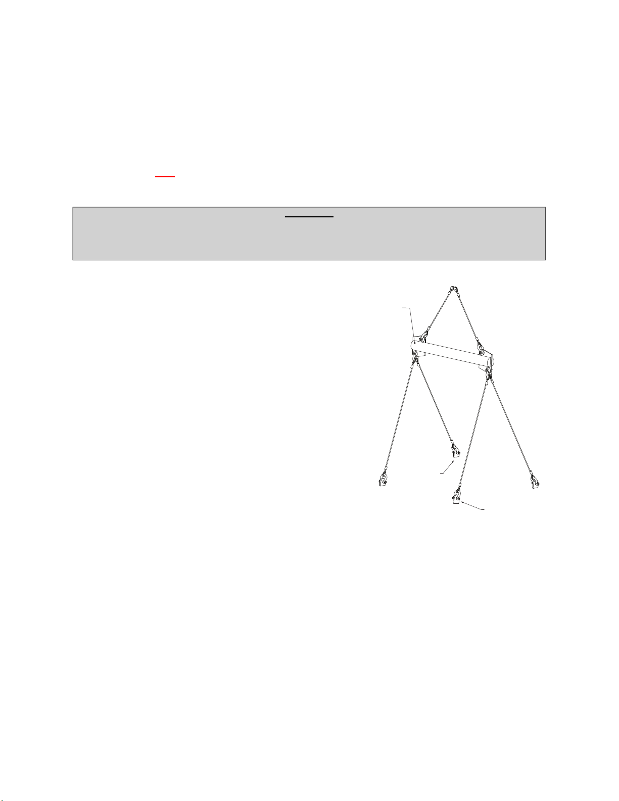
Mechanical ........................................................................................................................................................................... 5
Curb and Ductwork ............................................................................................................................................................... 7
Roof Mount Installation ......................................................................................................................................................... 8
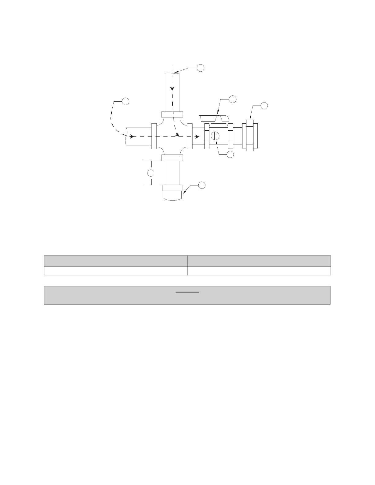
Gas ....................................................................................................................................................................................... 9
ELECTRICAL .......................................................................................................................................................................... 11
Fan to Building Wiring Connection ..................................................................................................................................... 12
Motorized Intake Damper ............................................................................................................................................... 13
Permanent Split Capacitor (PSC) Motor Speed Control .................................................................................................... 13
EVO™/ECM-VCU .......................................................................................................................................................... 13
Electronically Commutated Motor (ECM) Speed Control ................................................................................................... 14
External PWM Signal ..................................................................................................................................................... 14
Unit Mount Controller ......................................................................................................................................................... 14
Motor Speed Controller (MSC) Installation ......................................................................................................................... 15
MSC Controls Overview ..................................................................................................................................................... 16
MSC Menu ..................................................................................................................................................................... 16
Input Threshold .............................................................................................................................................................. 18
MSC Menu Tree ............................................................................................................................................................. 19
Remote Control Panel ........................................................................................................................................................ 20
Motorized Intake Damper ................................................................................................................................................... 20
Electric Cabinet Heater ...................................................................................................................................................... 20
Variable Frequency Drive (VFD) ........................................................................................................................................ 21
Variable Frequency Drive (VFD) Installation .................................................................................................................. 22
Input AC Power .............................................................................................................................................................. 22
VFD Output Power ......................................................................................................................................................... 22
VFD Programming ......................................................................................................................................................... 23
ACTECH SMV VFD ....................................................................................................................................................... 24
OPERATION ........................................................................................................................................................................... 25
Start-up Procedure ............................................................................................................................................................. 25
Pilot Adjustment ................................................................................................................................................................. 26
Main Burner Adjustment ..................................................................................................................................................... 27
Final Start-up Procedure ................................................................................................................................................ 28
Pulley Adjustment ............................................................................................................................................................... 29
Pulley Alignment/Proper Belt Tension ................................................................................................................................ 30
Pulley Combination Chart ................................................................................................................................................... 31
Sequence of Operation ...................................................................................................................................................... 32
Flame Safety Control ..................................................................................................................................................... 32
Modulating Gas System ..................................................................................................................................................... 34
High Temperature Limit ...................................................................................................................................................... 34
Optional Remote Panel Circuit ........................................................................................................................................... 35
Remote Panel Option .................................................................................................................................................... 36
Troubleshooting .................................................................................................................................................................. 37
Burner Troubleshooting ..................................................................................................................................................... 38
Remote Panel Troubleshooting Chart ............................................................................................................................ 39
MSC Troubleshooting .................................................................................................................................................... 40
MAINTENANCE ...................................................................................................................................................................... 41
General Maintenance ......................................................................................................................................................... 41
2 Weeks After Start-up ....................................................................................................................................................... 41
Every 3 Months .................................................................................................................................................................. 41
Yearly ................................................................................................................................................................................. 41
Burner Maintenance ...................................................................................................................................................... 42
Re-Setting of the Unit .................................................................................................................................................... 42
Emergency Shutdown of Unit ........................................................................................................................................ 42
Prolonged Shutdown of the Unit .................................................................................................................................... 42
Start-Up and Maintenance Documentation ........................................................................................................................ 44

4
WARRANTY
This equipment is warranted to be free from defects in materials and workmanship, under normal use and
service, for a period of 2-years from date of shipment. This warranty shall not apply if:
1. The equipment is not installed by a qualified installer per the MANUFACTURER’S installation
instructions shipped with the product.
2. The equipment is not installed in accordance with Federal, State, Local codes and regulations.
3. The equipment is misused or neglected, or not maintained per the MANUFACTURER’S maintenance
instructions.
4. The equipment is not installed and operated within the limitations set forth in this manual.
5. The invoice is not paid within the terms of the sales agreement.
The MANUFACTURER shall not be liable for incidental and consequential losses and damages potentially
attributable to malfunctioning equipment. Should any part of the equipment prove to be defective in
material or workmanship within the 2-year warranty period, upon examination by the MANUFACTURER,
such part will be repaired or replaced by MANUFACTURER at no charge. The BUYER shall pay all labor
costs incurred in connection with such repair or replacement. Equipment shall not be returned without
MANUFACTURER’S prior authorization, and all returned equipment shall be shipped by the BUYER,
freight prepaid to a destination determined by the MANUFACTURER.

5
INSTALLATION
It is imperative that this unit is installed and operated with the designed airflow and electrical supply in
accordance with this manual. If there are any questions about any items, please call the service
department at 1-866-784-6900 for warranty and technical support issues.
Mechanical
WARNING: DO NOT RAISE UNIT BY THE INTAKE HOOD, BLOWER, MOTOR SHAFT, OR
BEARINGS. USE ALL LIFTING LUGS PROVIDED WITH A SPREADER BAR OR SLING UNDER THE
UNIT.
Figure 1 - Spreader Bar
Site Preparation
1. Provide clearance around installation site to safely rig and
lift equipment into its final position (Figure 1). Supports
must adequately support equipment. Refer to
manufacturer’s estimated weights.
2. Locate unit close to the space it will serve to reduce long,
twisted duct runs.
3. Consider general service and installation space when
locating unit.
4. Do not allow air intake to face prevailing winds. Support
unit above ground or at roof level high enough to prevent
precipitation from being drawn into its inlet. The inlet must
also be located at least 10 feet away from any exhaust
vents. The fan inlet shall be located in accordance with the
applicable building code provisions for ventilation air.
Clearance
The top, back, and front surfaces of this heater may not be installed less than 6” from combustible
materials. The heater base may be installed on combustible surfaces. Allow 24” minimum service
clearance on both sides of this heater.
Spreader
Bar
Lifting Lugs
Lifting Lugs

6
Intake Assembly
Intakes and curbs (Figure 2) are shipped on a separate skid. Upon unit arrival, perform the following steps
to assemble the intake to the unit.
1. Apply silicone or weather-proof gasket on the backside of the flanges of the intake hood or V-bank
intake.
2. Secure the flanges of the intake hood to the unit with the supplied sheet metal screws.
3. Use caulk on the outside of the screws to prevent water leaks.
Figure 2 - Intake and Curb Assembly
123
4
1. Blower/Motor Access Door
2. Filtered Intake
3. Screened Intake
4. Curb

7
Curb and Ductwork
This fan was specified for a specific CFM and static pressure. The ductwork attached to this unit will
significantly affect airflow performance. When using rectangular ductwork, elbows must be radius throat,
radius back with turning vanes. Flexible ductwork and square throat/square back elbows should not be
used. Any transitions and/or turns in the ductwork near the fan outlet will cause system effect. System
effect will drastically increase the static pressure and reduce airflow.
•Table 1 shows the minimum fan outlet duct sizes and straight lengths required for optimal fan
performance.
• Do not use the unit to support ductwork in any way. This may cause damage to the unit.
•Follow SMACNA standards and manufacturer's requirements for the duct runs. Fans designed
for rooftop installation should be installed on a prefabricated or factory-built roof curb.
• Follow curb manufacturer’s instructions for proper curb installation.
• The unit should be installed on a curb and/or rail that meets local code height requirements.
• Make sure the duct connection and fan outlet are properly aligned and sealed.
• Secure fan to curb through vertical portion of the ventilator base assembly flange. Use a minimum of
eight (8) lug screws, anchor bolts, or other suitable fasteners (not furnished). Shims may be required
depending upon curb installation and roofing material.
• Verify all fasteners are secure. Figure 3 and Figure 4 show different mechanical installations.
• Adequate building relief shall be provided so as not to over pressurize the building when the heating
system is operating at its rated capacity. This can be accomplished by taking into account, through
standard engineering methods, the structure’s designed infiltration rate; by providing properly-sized
relief openings; or by interlocking a powered exhaust system; or by a combination of these methods.
• Heaters installed with intake ductwork must be purged to replace at least four air changes of the
volume of the intake duct.
• If the failure or malfunction of this heater creates a hazard to other fuel-burning equipment in the
building (e.g., when the heater is providing makeup air to a boiler room), the unit is to be interlocked to
open inlet air dampers or other such devices.
• On outdoor installations, it is recommended that the discharge duct be insulated to prevent
condensation during the “OFF” cycle in cold weather.
• Flexible connectors should be used on all ductwork connections. Vibration isolators are optional and
can be supplied in the loose parts package.
• Units that are installed in airplane hangars should be installed in accordance with the Standard for
Aircraft Hangars, ANSI/NFPA 409. Units that are to be installed in public garages should be installed in
accordance with the Standard for Parking Structures, ANSI/NFPA 88A, or the Standard for Repair
Garages, ANSI/NFPA 88B, and with CAN/CGA B149 Installation Codes.
Table 1 - Required Supply Ductwork
Duct Size Straight Duct Length
12” x 12” 36”

8
Roof Mount Installation
Note: Refer to submittal drawings for specific unit dimensions.
Figure 3 - Roof Mount Installation Details
Figure 4 - Indoor Inline
1
AIRFLOW
2
3
4
5
6
9
8
7
10
1. Discharge Opening
2. Curb Outer Wall
3. Flex Conduit for Field Wiring
4. Screened Intake
5. Filter Access Door
6. Service Disconnect Switch
7. 1/2” NPT Pipe
8. Blower/Motor Access Door
9. Control Drop
10. Motor Drop
1. Service Disconnect Switch
2. 1/2” NPT Pipe
3. Optional Unistrut Base for
Hanging
A. 1” Spacing from Unistrut to edge
of unit
B. 36” Unistrut
C. Unit Height
AIRFLOW
MOTOR
BLOWER/
DOOR
ACCESS
A
1
B
2
3
A
C

9
Gas
Installation of gas piping must conform with local building codes, or in the absence of local codes to the
National Fuel Gas Code, ANSI Z223.1 (NFPA 54) – latest edition. In Canada, installation must be in
accordance with CAN/CGA-B149.1 for natural gas units and CAN/CGA-B149.2 for propane units.
WARNING: INLET GAS PRESSURE MUST NOT EXCEED PRESSURE INDICATED ON NAMEPLATE.
SEE UNIT NAMEPLATE FOR PROPER GAS SUPPLY PRESSURE AND GAS TYPE.
1. Always disconnect power before working on or near a heater. Lock and tag the disconnect switch or
breaker to prevent accidental power-up.
2. Piping to the unit should conform to local and national requirements for type and volume of gas
handled, and pressure drop allowed in the line. Refer to the Gas Engineer’s Handbook for gas line
capacities.
3. The incoming pipe near the heater should be sized to match the connection on the outside of the unit.
Unit inlet sizes are shown in Table 2. The unit requires a steady supply of gas at all times, avoid
multiple taps in the gas supply line.
4. Install a ground joint union with brass seat and a manual shut-off valve external to the unit casing.
Install shut-off valve adjacent to the unit for emergency shut-off and easy servicing of controls. Refer to
Figure 5.
5. Provide a sediment trap, as shown in Figure 5, before each unit and where low spots in the pipeline
cannot be avoided.
6. Clean out the gas line to remove debris before making connections. Purge gas line to remove air
before attempting to start unit. Purging air from gas lines should be performed as described in ANSI
Z223.1-latest edition “National Fuel Gas Code,” or in Canada as described in CAN/CGA-B149.
7. All field gas piping must be pressure/leak tested before unit operation. Use a non-corrosive bubble
forming solution or equivalent for leak testing. The heater and its individual shut-off valve must be
disconnected from the gas supply piping system during any pressure testing of that system at test
pressures in excess of 1/2 psi.
8. This unit requires the gas pressure to be within the unit’s minimum and maximum gas pressure
ratings. If the pressure is greater than the maximum, the internal valve components will be damaged. If
the pressure is below the minimum, the heater will not perform to specifications. Refer to Table 3 on
page 10.
Table 2 - Gas Connection Sizes
Unit Size Gas Pipe Size (NPT)
76 1/2”

10
Figure 5 - Gas Connection Diagram
Table 3 - Gas Pressure
Gas Pressure Type Gas Pressure
Natural/LP 5 - 14 Inches WC Maximum
NOTICE
Refer to the heater’s rating plate for determining gas supply pressures and requirements.
1
12
3
4
5
A
1. Gas Supply Line Connection
2. Manual Gas Shut-off Valve
3. Ground Joint Union with Brass Seat
4. Plugged 1/8” NPT Test Gauge Connection
5. Sediment Trap
A. Minimum Depth = 3”

11
ELECTRICAL
Before connecting power to the heater, read and understand the entire section of this document. As-built
wiring diagrams are furnished with each unit by the factory and are attached to the control module’s door
or provided with paperwork packet.
Electrical wiring (Table 4) and connections must be made in accordance with local ordinances and the
National Electric Code, ANSI/NFPA 70. Verify the voltage and phase of the power supply, and the wire
amperage capacity is in accordance with the unit nameplate. For additional safety information, refer to
AMCA publication 410-96, Recommended Safety Practices for Users and Installers of Industrial and
Commercial Fans.
1. Always disconnect power before working on or near this equipment. Lock and tag the
disconnect switch and/or breaker to prevent accidental power-up.
2. An electrical drop containing the line voltage power wiring is shipped with every unit. The electrical
drop should be brought through one of the conduit openings located in the base of the unit, run
through the curb, and connected to a junction box inside the building.
3. A dedicated branch circuit should supply the motor circuit with short circuit protection according to the
National Electric Code. This dedicated branch should be run to the junction box.
4. Verify that the power source is compatible with the requirements of your equipment. The nameplate
identifies the proper phase and voltage of the equipment.
5. Units shipped with optional remote panels require a second drop through the base of the unit. It is
important to route the motor wires in a separate conduit from the wiring.
6. Before connecting the unit to the building’s power source, verify that the power source wiring is de-
energized.
7. Secure the power cable to prevent contact with sharp objects.
8. Do not kink power cable and never allow the cable to encounter oil, grease, hot surfaces, or chemicals.
9. Before powering up the unit, make sure that the fan rotates freely. Make sure that the interior of the unit
is free of loose debris or shipping materials.
10. If any of the original wire supplied with the unit must be replaced, it must be replaced with type THHN
wire or equivalent.
WARNING!!
Disconnect power before installing or servicing unit. High voltage electrical input is needed for
this equipment. A qualified electrician should perform this work.
Table 4 - Copper Wire Ampacity
Wire Size AWG Maximum Amps
14 15
12 20
10 30
8 50
6 65
4 85
3 100
2 115
1 130

12
Fan to Building Wiring Connection
Figure 6 - Wiring Connection Details
1. Disconnect Switch
2. Galflex Conduit (In Unit)
3. Factory Wiring
4. Field Supplied Wiring - From building power or
pre-wired control panel.
WHBK GR
120V 1 PH.
RD
BK GR
208-240V 1 PH.
BKBK BK GR
208-240/460/600V 3 PH.
1
2
3
4
1
2
3
4
1
2
3
4
WH - WHITE
RD - RED
WIRE COLOR
BK - BLACK
GR - GREEN
Single Point Connection

13
Permanent Split Capacitor (PSC) Motor Speed Control
Figure 7 - PSC Motor Speed Control
Some single-phase direct-drive fans contain speed controls that
regulate the amount of voltage going to the motor. Specific PSC
motors must be used in conjunction with speed controls. The
speed control has a knob (Figure 7) with an off position along
with high to low range. At high speed, the speed control allows
all of the line voltage to pass directly to the motor.
A minimum speed adjustment is provided to allow independent
control of the minimum speed setting. Minimum speed
adjustment ensures the motor runs with sufficient torque to
prevent stalling. To adjust this:
1. Motor must be in actual operating conditions to achieve proper speed adjustment. Motor will not slow
down unless proper load is applied.
2. Turn main control knob to lowest speed position.
3. Locate and adjust minimum speed setting. This can be found under the speed control faceplate. Use a
small screwdriver to adjust. Rotate clockwise to decrease minimum speed; counter-clockwise to
increase minimum speed.
4. Motor will now operate from this preset minimum speed to full speed.
The lowest minimum voltage that may be applied to these motors is 65V AC. Running lower
voltages to the motor can cause premature failure and overheating problems.
Vari-Speed
HIGH
LOW
OFF
SOLID STATE SPEED CONTROL

14
Electronically Commutated Motor (ECM) Speed Control
An Electrically Commutated Motor (ECM) with speed control allows for an accurate manual adjustment of
the fan’s speed. The benefits of using an EC motor is exceptional efficiency, performance, and motor life.
External PWM Signal
The fan unit will be shipped with power wiring and communication wiring fed to an internal junction box.
The fan is shipped with Shielded Twisted Pair (STP) wire which is used to wire to a remote PWM signal.
Red wire is used to go to the positive PWM signal, black wire is used to go to the negative PWM signal.
Reference schematics for all wiring connections. STP is connected to the communication wiring of the
motor using wire nuts in the junction box. If a preset length of STP is provided, it will be connected to the
junction box from the factory. Run the STP through any available knockout in the fan base.
Unit Mount Controller
The RTC speed controller features a 4 digit LED display with a five button interface. All parameters can be
accessed through the user menu. The percent of run speed can be changed by using the Up and Down
buttons followed by pressing Enter (middle button) to save changes. Every ten seconds the display will
toggle between current percentage of run speed and current RPMs. The flow index has a range of 0-100%
and is typically linear with motor RPM.
If the remote function (re) is enabled, the speed is controlled through a 0-10V input. 0V = 0% and 10V =
100%, unless overridden by the low speed and high speed limits.
The speed controller requires a 24V AC input and can locally turn the motor on and off. The motor RPM
range is fully adjustable between the minimum and maximum setpoints, see LSPD and HSPD on the
programming display. For more information, see the RTC control operating manual.
For all motors except 16Z, 18Z, 20Z, 22Z, 25Z, 28Z: If “oFF” is being displayed, and the speed is set
above 300 RPM, the ECM is not receiving RPM feedback. Check that the ECM is wired correctly. Check
that the motor “tyP” in the settings matches the motor manufacturer. 16Z, 18Z, 20Z, 22Z, 25Z, 28Z do not
send RPM feedback.
NOTE: A Variable Frequency Drive (VFD) is required to adjust the speed control of a non-
electrically commutated 3-phase direct-drive motor.
Figure 8 - RTC Speed Controller and Menu
Column 1 Column 2
APPS
SP
LSPD
DN UP
hSPD
tyP
FSC
0-10
20
20
100
nid
TC42
TC48
re dABl
EnAb
ver
LT RT
1.0
Select the application
Setpoint/Speed of the motor
Set the low speed limit
Set the high speed limit
Select motor type
Enable/Disable remote
View software version number
Fan Speed Control Application
Programmable 0-10V reference
Default Setpoint
Lowest speed motor will operate
Highest speed motor will operate
Nidec/Ziehl Motor
Telco Green TC42 Motor
Telco Green TC48 Motor
Disable remote
Enable remote

15
Motor Speed Controller (MSC) Installation
The Motor Speed Controller (MSC) is a versatile device able to output various signal types to many
different Electrically Commutated Motors (ECMs). The MSC signal output types can be selected under the
‘Motor Type’ section of the MSC menu. The MSC may be installed in a fan, remotely in a kitchen space, or
in a mechanical room. While this device can be mounted remotely and powered using 24V, it may also be
mounted with the fan where it will be exposed to higher voltages. If installed in the fan, the electrical
installation must be carried out according to the appropriate regulations (e.g., cable cross-sections, circuit
breaker, protective earth [PE] connection). National and local codes must be followed during the
installation process.
The MSC board may be powered through a 120VAC/24VAC CLASS 2 transformer, 120V AC/24V DC
CLASS 2 power supply, or through MODBUS connections.
The MSC contains static sensitive components. Therefore, you must handle with care to avoid damage to
these components. All operations concerning installation, commissioning, and maintenance must be
carried out by qualified, skilled personnel who are familiar with the installation, assembly, commissioning,
and operation of the electronic board and the application for which it is being used.
Ensure proper handling and avoid excessive mechanical stress. Do not bend any components when
handling or installing component. Do not touch any electronic components or contacts.
Precautions must be adhered to during installation, testing, servicing, and repairing of this board.
Component damage may result if proper procedures are not followed.
Do not install the MSC where it is subjected to adverse environmental conditions such as combustibles,
oils, hazardous vapors, corrosive chemicals, excessive dust, moisture, direct sunlight, or extreme
temperatures. When removing or installing the MSC to the j-box, verify the gasket is present. All electrical
connections for the MSC are located on the backside of the controller. Refer to Figure 9 for details on
installation and electrical connections. When the micro USB programming port is not in use, place the
weather-seal plug into the port location.
Figure 9 - Installation/Electrical Connections
Backside - Electrical Connections
INCOUTC
VAC
0-1024
C
J3J2
J8J7
0-10
J-Box
#8-32 x 1/2”
Screw
#8-32 x 1/2”
Screw
Gasket
Micro USB
Programming
Port

16
MSC Controls Overview
There are four buttons to navigate through the menu screens, refer to Figure 10.
Press the MENU button to access menu settings/parameters, pressing MENU will also back out of the
current menu screen. To scroll through menus, use UP and DOWN buttons. Press the ENTER button to
change setting/parameter selection.
To enter password, press MENU, then press ENTER when “Board Config” is displayed. Use UP and
DOWN to scroll through numbers, press ENTER to advance to the next numerical setting. To save
changes, press MENU until the screen displays “SAVE CHANGES? [ENTER] TO SAVE.” Press the
ENTER button to save changes.
Figure 10 - MSC Front Detail View
MSC Menu
Board Config - Password (default is 0225)
•Motor Type - User may change motor type between Nidec, Telco 42, Telco 48, Ziehl,
0-10V, Other.
•Control Type - This setting adjusts how the fan will be controlled.
• Local - The fan will be controlled by the MSC.
• Remote Modbus - The fan will be controlled by another master board through the MSC. A
connection between the 0-10V Out to 0-10V In must be made for start command.
• Remote 0-10V - The fan will be controlled by an external 0-10V signal.
•Speed Settings - Provides access to speed and voltage settings.
• Low Speed - Adjustable speed from 20% up to high speed setting, or 0-10V. Setting cannot go
above High Speed parameter.
• High Speed - Adjustable speed from 100% down to low speed setting, or 10-0V. Setting cannot go
below Low Speed parameter.
• Set Speed% - Adjustable speed range is dependent on Low Speed and High Speed settings. This
controls the output of the motor.
• Voltage Range - Only available when Motor Type “OTHER” is selected. Default setting is 24V. 5V,
and 10V are also available.
Menu Up Down Enter
Micro USB
Programming Port
(For Service Use Only)
SPEED%: 0
RPM: 0
Control Type:
LC = Local
MB = Remote Modbus
10V = Remote 0-10V
EXT = External Device
LC
MOTOR SPEED CONTROLLER
MSC

17
•Modbus # - Adjustable Modbus ID. Exhaust Fan range 11-18, Supply Fan range 21 or 22. A VFD and
MSC cannot use the same Modbus #.
•Options
• Feedback Fault - If set to ENABLED, the MSC will monitor RPM feedback. If the MSC does not
receive data for 30 seconds or 70% of the expected RPM, this fault will be displayed. Ziehl motors
do not provide feedback.
• 2 Speed - The 0-10V output cannot be used when the 2 Speed or Manual Speed options are On,
or if the “Control Type” is set to Modbus. When the 0-10V OUT and 0-10V IN terminals are not
jumped together, the fan will operate at low speed. When 0-10V OUT and 0-10V IN terminals are
jumped together, the fan will operate at high speed.
• Analog Speed - The user may enable/disable the option, and calibrate a potentiometer for proper
operation that is connected between the 0-10V OUT and 0-10V IN terminals. When enabled, you
must calibrate the potentiometer. Follow the MSC’s on-screen instructions. The speed will be
adjustable between 0V (low speed) to 10V (high speed).
• Input Threshold - When control type is set to Remote 0-10V, an input threshold will be created for
motor control. Refer to Figure 11 on page 18 for threshold examples.
• Zero Operation - The user may select how the motor will operate when the
0-10V input is at 0V. The options will be Off or Low Speed (default).
• Threshold - Increasing the threshold value will allow for the device to hold its voltage/RPM
output while the input is between the 0 - threshold value.
•Restore Settings - Provides access to restore factory settings, and test & balance settings.
• Factory Settings - This will reset all values back to factory settings.
• T & B Settings - This will reset all values back to last saved test & balance settings.
•Change Password - Users may update the password setting to their own. Password 0225 will also be
stored for backup. Both passwords will allow users to enter “Board Config” settings.
Software Version - Displays the current software version installed on the board.
Faults - This provides access to “Fault History,” “Fault Totals,” and “Clear Faults.”
•Fault History - Displays fault history and board reboots in chronological order. Possible displayed
faults are:
• No Faults - There are no active faults with the system.
• Feedback Fault - Only displayed for motors with feedback capabilities.
• Reboot - Any time the fan goes from OFF to ON, this “fault” will be logged. This fault will only
display in “Fault History.”
• Modbus - Issue with Modbus communication between the MSC and master board.
• Variable Device Fault - When “Analog Speed” is selected and a potentiometer is connected, if the
voltage drops below 1V, this fault will be displayed.
•Fault Totals - Displays amount of faults for Modbus, Feedback, Var Device, Reboot, and Total Faults.
•Clear Faults - Users may clear all faults from the board.
Service - This provides access to service settings. Password: 1234
•Save T & B - After the test & balance process has been completed, save adjustments under this
menu.
•IO Status - Provides access to information about the inputs and outputs of the MSC board.
• V In - Displays the incoming voltage (0-10V) to the MSC.
• V Out - Displays the output voltage (0-10V) to the motor.
• RPM - Displays motor RPM feedback. Ziehl motors do not provide feedback.
• PWM V - Displays equivalent voltage reading of the PWM output to the motor.
• Speed% - Displays PWM percentage output value to the motor.

18
Input Threshold
Figure 11 - Input Threshold Examples
OFF
HIGH SPEED
01 423 6785910
OPERATING
BAND
INPUT VOLTS
0-10V OR PWM
OUTPUT SIGNAL
DEPENDANT ON
SETTINGS
0-10V INPUT
Factory Default: Zero operation set to low speed, threshold set to 0V.
LOW
SPEED
DEVICE OUTPUT
HIGH SPEED
01 423 6785910
OPERATING
BAND
INPUT VOLTS
0-10V OR PWM
OUTPUT SIGNAL
DEPENDANT ON
SETTINGS
0-10V INPUT
DEVICE OUTPUT
LOW SPEED
Zero operation set to low speed, threshold set to 2V.
OFF
HIGH SPEED
01 423 6785910
OPERATING
BAND
INPUT VOLTS
0-10V OR PWM
OUTPUT SIGNAL
DEPENDANT ON
SETTINGS
0-10V INPUT
DEVICE OUTPUT
Zero operation set to off, threshold set to 2V.

19
MSC Menu Tree
RANGE: NIDEC, TELCO 42, TELCO 48 (DEFAULT),
ZIEHL, 0-10V, OTHER
BOARD CONFIG
MOTOR TYPE
RANGE: LOCAL (DEFAULT),
REMOTE MODBUS, REMOTE 0-10V
CONTROL TYPE
SPEED SETTING LOW SPEED RANGE: 20%-100% or 0-10V
DEFAULT: 20% or 0V
HIGH SPEED RANGE: 20%-100% or 0-10V
DEFAULT: 100% or 10V
SET SPEED % RANGE: 20%-100% or 0-10V
DEFAULT: VARIES
VOLTAGE RANGE RANGE: 5V, 10V, 24V
DEFAULT: 24V
RANGE: 11-18 (EXHAUST FAN) / 21 or 22 (SUPPLY FAN)
DEFAULT: 11
MODBUS #
FEEDBACK FAULT
OPTIONS
FACTORY RESTORE?
[ENTER] TO RESTORE
RESTORE SETTINGS
PASSWORD
0000
CHANGE PASSWORD PASSWORD OK?
0000
SOFTWARE VERSION
FAULTS
CURRENT SOFTWARE VERSION
DISPLAYED
DISPLAYS FAULTS DAY/HOUR/MINUTE/SECONDS
DISPLAYS BOARD REBOOT
FAULT HISTORY
FAULT TOTALS FEEDBACK, MODBUS, REBOOT, VARIABLE DEVICE,
and TOTAL FAULT COUNTS ARE SHOWN
2 SPEED
ANALOG SPEED
RANGE: 20%-100% or 0-10V
DEFAULT: VARIES
ENABLED/DISABLED/CALIBRATION
ENABLED/DISABLED
DEFAULT: DISABLED
CLEAR FAULTS CLEAR FAULTS?
[ENTER] TO CLEAR
IO STATUS
DISPLAYS INCOMING VOLTAGE (0-10V) TO THE MSC.
V IN
V OUT
RPM DISPLAYS MOTOR RPM FEEDBACK. ZIEHL MOTORS
DO NOT PROVIDE FEEDBACK
PWM V DISPLAYS EQUIVALENT VOLTAGE READING OF THE
PWM OUTPUT TO THE MOTOR.
SPEED % DISPLAYS PWM PERCENTAGE OUTPUT VALUE TO
THE MOTOR.
DISPLAYS OUTPUT VOLTAGE (0-10 V) TO THE
MOTOR.
INPUT THRESHOLD ZERO OPERATION
THRESHOLD
RANGE: OFF - LOW SPEED
DEFAULT: LOW SPEED
RANGE: 0-10V
DEFAULT: 0V
SERVICE
SAVE T & B T & B SAVE?
[ENTER] TO SAVE
FACTORY SETTINGS
T & B SETTINGS T & B RESTORE?
[ENTER] TO RESTORE

20
Remote Control Panel
On units shipped with the optional remote control panel, an electrical drop containing the panel wiring is
provided with the heater. There is a terminal strip inside the remote panel that matches the terminals in the
heater unit. The remote panel should be wired as shown in Figure 12. Wiring may vary by unit, refer to
electrical schematics that were provided with your unit.
Figure 12 - Typical Remote Control Panel Wiring
Motorized Intake Damper
On units shipped with the optional motorized intake damper, a power transformer is supplied with the unit if
the main incoming voltage is greater than 120V. The damper motor is automatically energized when the
main disconnect switch is in the ON position. No external wiring to the damper motor is required.
Electric Cabinet Heater
On units shipped with an optional electric cabinet heater, ensure that the heater is wired to a separate
120V, 15 amp input, the thermostat sensing bulb is mounted correctly in the control vestibule where the
heater is located, and the thermostat set to 0 Degrees Fahrenheit.
WH
1
2
9
8
N
70
GY
BR
BK
OR
60
50
YW
17
10
18
T1
T3 BK
RD
PK
RD
8040
Temperature Control
Off
Auto
Manual
Heat
Vent
Flame Failure
Burner On
Direct-Fired Remote Panel
Blower On
Power
Off
Auto
Manual
Vent
Cool
Heat
Direct-Fired Remote Panel
Off
Auto
Manual
Heat
Vent
Direct-Fired Remote Panel
18
17
10
18
T4
T5
Temperature Control
Flame Failure
Burner On
Blower On
Power
40
50
60
YW
11 BL
T1
T3
18
RD
BK
80
70 WH
OR
9
17
10 RD
PK
BR
8
N
GY
1
2BK
Flame Failure
YW
BK
RD
T1
T3
Direct-Fired Remote Panel
Vent
Heat
Flame Failure
Burner On
Off
Auto
Manual
Blower On
Power
Temperature Control
55
60
65
90
80
85
70
55
75
90
N
9
8
2
1
BK
RD
YW
PK
RD
WH
GY
BR
BK
OR
60
Temperature Control
Burner On
Blower On
Power
50
40 80
70 WH
GY
BR
OR
PK
RD
9
17
10
8
N
BK
2
1
NO
NC
BK
1
C
PR
E
2-POSITION DIRECT FIRED REMOTE PANEL 3-POSITION DIRECT FIRED REMOTE PANEL WITH EXHAUST ON IN FIRE CONTROL
3-POSITION DIRECT FIRED REMOTE PANEL WITH SPACE HEATING CONTROL3-POSITION DIRECT FIRED REMOTE PANEL WITH COOLING CONTROL
11
11
22
22
3
4
3
3
3
1. Motor Connection
2. Control Connection
3. Shielded Cable
4. Fire System Micro-switch
Table of contents
Popular Heater manuals by other brands

Supplies4Heat
Supplies4Heat SAXON Fitting instructions

Gabarron
Gabarron RXE Plus Installation instructions and user guide

Wetekom
Wetekom 89 58 03 Original instruction manual

Hotech
Hotech HC501 Instruction booklet

Domus
Domus PROFAN-4 installation manual

Frico
Frico Thermozone AG 4000 A Series Assembly and operating instructions