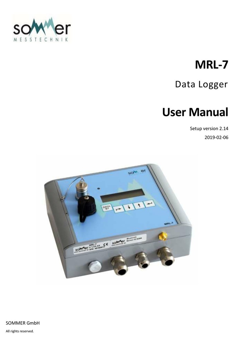
SOMMER MRL-7 User manual

MRL-7
Data Logger
User Manual
Manual Version: V01
2017-06-30
SOMMER GmbH
All rights reserved.

The copyrights for this manual are exclusively at the company
SOMMER GmbH
A-6842 Koblach
This manual may only be multiplied or passed on to third-parties with written permission of the company SOMMER. This applies also if
only excerpts of this manual are copied or passed on.
The same conditions apply for the passing on in digital form.
SOMMER GmbH
Strassenhaeuser 27
6842 Koblach
Austria
www.sommer.at
Distributed exclusively in the USA by
www.hydrologicalusa.com

CE compliance
This product is in conformity with the following standards
EN 60950-1
EN 61326-1
EN 61010
following the provision of directive R&TTE 1999/5/EC.
Information regarding images –image disclaimer
All images used in this manual are for illustrative purposes only. The actual product, the scope of
delivery or individual features may vary.
Safety information
Please readthisentiremanual before setting up oroperating this equipment.The non-compliance
of this manual could result in damage to the equipment. Also in the case of non-compliance
injuries of individuals cannot be excluded totally.
To make sure that the protection provided of and by this equipment is not impaired, do not use or
install this equipment in any manner other than that specified in this manual.

Table of contents
1. Overview of the installation steps ...................................................................................... 1
2. Logger functions and interfaces......................................................................................... 2
2.1. MRL-7 key functions and features ................................................................................... 2
2.2. Measurement and data storage concept.......................................................................... 3
2.2.1. Performing measurements.........................................................................................3
Analogue measurement example ....................................................................... 3
RS-485 measurement example.......................................................................... 3
SDI-12 measurement example........................................................................... 4
2.2.2. Storing of measurement results and storage options..................................................5
2.2.3. Conditional storage....................................................................................................5
2.3. User interfaces................................................................................................................ 6
2.3.1. Keyboard and display.................................................................................................6
2.3.2. Display menu structure ..............................................................................................6
2.3.3. Parameterisation and data transfer............................................................................7
2.4. Sensor connections and sensor power supply................................................................. 7
2.4.1. Analogue interfaces ...................................................................................................7
2.4.1. Digital interfaces ........................................................................................................8
SDI-12................................................................................................................ 8
RS-485............................................................................................................... 9
3. Hardware ............................................................................................................................ 10
3.1. How to open the housing............................................................................................... 12
3.2. Mounting the MRL-7...................................................................................................... 13
3.3. Modem.......................................................................................................................... 14
3.4. Micro SIM Card, Micro SD Card and Button Cell Battery............................................... 14
3.4.1. Insert / Exchange of Micro SIM Card........................................................................15
3.4.2. Insert / Exchange of Micro SD Card.........................................................................16
3.4.3. Exchange of button cell............................................................................................17
3.5. Pin description............................................................................................................... 18
3.6. Spring Clips................................................................................................................... 21
4. USB..................................................................................................................................... 23
4.1. Requirements for flash drive.......................................................................................... 23
4.2. Reading out data via USB ............................................................................................. 23
5. MRL-7 keyboard operation................................................................................................ 25
5.1. Description of keyboard buttons, navigating the menu................................................... 25
5.2. Activating the display..................................................................................................... 26
5.3. Deactivating the display................................................................................................. 26
5.4. Reading (current) measurement values......................................................................... 26
5.5. Adjusting measurement values...................................................................................... 26
5.6. Settings......................................................................................................................... 27
6. Parameterisation................................................................................................................ 29
6.1. Commander................................................................................................................... 29
6.2. Defining a local connection with the MRL-7................................................................... 29
6.2.1. RS-232.....................................................................................................................30
6.2.2. Bluetooth..................................................................................................................34
6.3. Commander: Establishing a connection......................................................................... 39
6.4. Defining a station........................................................................................................... 40
6.5. Establish a connection to a “Station”.............................................................................. 43
6.6. Downloading stored data............................................................................................... 43

6.7. Remote connection via IP Call.......................................................................................44
6.8. Data transmission via HTTP/FTP...................................................................................45
6.9. Time synchronisation.....................................................................................................45
7. Description of the parameters...........................................................................................46
8. Technical specifications....................................................................................................74
9. Appendix.............................................................................................................................75
9.1. Changing parameters via a terminal...............................................................................75
9.2. Error messages..............................................................................................................75
9.3. Index of tables ...............................................................................................................77
9.4. Index of figures..............................................................................................................77


www.sommer.at page 1
1. Overview of the installation steps
The following overview lists the most important steps for a full installation of the MRL-7 data
logger. The installation is divided in creating and establishing a connectionwith the MRL-7 and
defining a station. Additionally, the most important settings andmeasurements to beperformed
have to be defined.
1.
Installation of “Commander” (chapter 6.1)
2.
Define a “Connection” for being able to communicate with the MRL-7 (chapter 6.2)
3.
Establish a “Connection” with the MRL-7 (chapter 6.3)
4.
Define a “Station” for easy data management (chapter 6.4)
5.
Set the MRL-7 parameters as required
a.
Set the language and decimal character (chapters J-A and J-B)
b.
Set the station number and station name assigned to the MRL-7 (chapters A
and B)
c.
Set the global measurement and storage interval (chapters C and D)
d.
Define the number of measurement values to be stored (chapter E)
e.
Define measurements to be performed and/or values to be retrieved from
connected sensors (chapter G)
f.
Configure the modem and data transmission parameters (chapters 6.7, 6.8 and
Description of the Parameters chapter I)
g.
Adjust the advanced (“Technics”) settings as per your requirements (chapter J)
6.
Download stored data (chapters 4.2 and 6.6)
Attention: You must not connect any voltages bigger than 30 volts anywhere to the
logger or to any pin. Applying voltages above 30 volts you risk your health, physical
damages on the device or even a fire!

www.sommer.at page 2
2. Logger functions and interfaces
2.1. MRL-7 key functions and features
Fig. 1: MRL-7 key functions and features

www.sommer.at page 3
Advantages and main characteristics of the MRL-7 data logger
Reliable and energy-saving: optimised to collect monitoring data in remote areas
without any infrastructure
Logger can be operated fully independently (with batteries or solar-module), integrated
solar charge controller; no equipment cabinet required due to IP 67 rating
Ideal integration and compatibility with complete SOMMER sensor family as well as
common sensor technology products
Backlit display for easy data readout and logger parameterisation
Parameterisation via RS-232 and Bluetooth or via IP-call / modem connection
Data readout with USB memory stick, Bluetooth-interface, RS-232 or via IP-call /
modem connection
Minimum energy demand
Solid, compact, weatherproof aluminium box
Integrated remote data transmission through modem (2G / 3G and optionally 4G)
2.2. Measurement and data storage concept
2.2.1. Performing measurements
Analogue measurement example
In this example three analogue inputs (An1, An2, An3) are measured. The diagram below
shows the first and second measurement intervals.
Fig. 2: Analogue measurement
Every measurement interval starts with the user defined holdback time (see J-I-E). Then An1
is measured three times (see J-I-F and J-I-G) and so are An2 and An3.
After the last measurement is completed, the sensor supply voltage is switched off until the
next measurement interval starts again.
RS-485 measurement example
In this example three measurement values are requested from a sensor connected via the RS-
485 interface. The diagram below shows the first and second measurement interval.

www.sommer.at page 4
Fig. 3: RS-485 measurement
At the beginning of every measurement interval the MRL-7 activates the RS-485 interface and
issues three trigger commands to the sensor connected. As soon as all requested results are
received by the data logger, the RS-485 interface is switched off automatically.
If the requested results are not received within the “Trig, timeout”(see J-G-I) the RS-485
interface is also switched off and the last values received are stored (again).
SDI-12 measurement example
In this example the measurement values are requested from three SDI-12 sensors connected.
The diagram below shows the first and second measurement intervals.
Fig. 4: SDI-12 measurement
At the beginning of every measurement interval the MRL-7 issues a M-command to the first
sensor which is answered with information about the number of measurement values available
and the time until the data is ready to be requested by the data logger. After e.g. one second
the MRL-7 issues a D-command to retrieve the measurement results from the sensor.
In this example the SDI-12 sensor addresses are “0”, “1” and “2”.
Table 1: SDI-12 example commands and answers
Example commands and answers
Command issued
Answer received
Comment
a
0M!
00013<CR><LF>
3 values are available in 1 second
b
0D0!
0+1.1+2.2+3.3><CR><LF>
3 values: “1.1”, “2.2”, “3.3”
c
1M!
10022<CR><LF>
2 values are available in 2 seconds
d
1D0!
1+4.4+5.5<CR><LF>
2 values: “4.4”, “5.5”
e
2M!
20031n<CR><LF>
1 value is available in 3 seconds
f
2D0!
2+6.6<CR><LF>
1 value: “6.6”
For detailed information about SDI-12 please see the official website www.sdi-12.org.

www.sommer.at page 5
2.2.2. Storing of measurement results and storage options
Measurement results are recorded in a separate storage interval.
The storage interval must always be equal or bigger than the set measurement interval.
The reason for using a separate storage interval is the advantage of being able to store
minimum, maximum and/or mean values of measurement results. These can be set with the
software Commander (see chapter G “Measurements, table”, column “Function”) or via the
terminal menu (see 9.1).
Fig. 5: Example storage interval
In above example the analogue inputs An1, An2 and An3 are used to measure the outputs of
three sensors. Because the storage interval covers two measurement intervals, it is possible
to store either the mean value, the minimum or the maximum values measured within the set
storage interval. If none of the aforementioned options is chosen, the stored value will be the
last available measurement result(s) within the storage interval.
2.2.3. Conditional storage
Some measurement values are only stored when their value has changed since they were last
stored. For these measurement values an alternative storage interval can be defined (see J-
D-B) and the values can be reset to “0” once per day (see J-D-A).
The sensor types (“S-Typ”) using the conditional storage interval by default are “COUNT” and
“SYS” values (see chapter G “Measurements, table” for more information).

www.sommer.at page 6
2.3. User interfaces
2.3.1. Keyboard and display
The MRL-7 display is being activated by pressing any of the buttons.
The cursor buttons , , and are used to navigate the on-screen menu.
Key
Function(s)
Exit the current menu / Abort
Menu item down / Decrease value
Menu item up / Increase value
Enter the currently displayed menu item / Confirm /
Trigger measurement
2.3.2. Display menu structure
The following table shows the on-screen menu structure.
It shows an example setup consisting of a temperature and humidity measurement and a snow
depth measurement.
Table 2: Display menu structure
Start screen
Displays the station number, current date and time.
* Measurements *
Main menu item containing all measured values
01
Temperature (e.g. -5.58 °C) *
02
Humidity (e.g. 62.35 %) *
03
Snow depth (e.g. 436 mm) *
*** Stored V ***
Main menu item containing all stored values
01 - 03
Temperature, Humidity, Snow depth *
*** Settings ***
see chapter 5.6 „Settings“
**** Status ****
Status information
1
Station No.
2
SOMMER ID
3
Station name
4
Date
5
Time

www.sommer.at page 7
6
Software version
7 **
IMSI
8 **
State
9 **
Type (Modem)
10 **
Signal (CSQ)
Values marked with “ * ” are measured / stored values, all others are system values.
Menu items marked with “ ** ” relate to the logger modem.
2.3.3. Parameterisation and data transfer
Several interfaces are available to download stored data and/or to change MRL-7 parameter
settings:
Table 3: Interface types and features
Interface type
data readout
changing parameters
Keyboard and display
USB flash drive (see chapter 4)
X
Bluetooth connection (see chapter 6.2.2)
X
X
Serial interface (see chapter 6.4)
X
X
IP call (see chapter 6.7)
X
X
automatic data transmission via
HTTP/FTP (see chapter 6.8)
X
Time synchronisation via time server –
NTP (see chapter 6.9)
2.4. Sensor connections and sensor power supply
2.4.1. Analogue interfaces
Table 4: Analogue inputs
Analogue input
type / range
An 1
0 … 2.5V
An 2
0 … 2.5V

www.sommer.at page 8
An 3
configurable:
- 0 … 2.5V
- NTC
- resistor > 2kΩ
An 4
configurable:
- 0 … 2.5V
- 0 … 0.3V
- resistor > 1k25Ω
- resistor < 1k25Ω
- PT1000
Wind –speed
frequency measurement
Wind –direction
resistor measurement
Counter 1
counts voltage pulses (min. 5V)
Counter 2
counts voltage pulses (min. 5V) up / down
Attention: Counter 2 is no additional input. It replaces wind direction (either/or)!
All analogue sensorscan be supplied via theinternally provided voltage outputs. See technical
data of MRL-7 and sensor used for more details and specific requirements.
Table 5: Supply voltage outputs
Output
Maximum load
5V-Out
100mA (max. sum current over all sensors)
12V-Out
200mA (max. sum current over all sensors)
2,5V Reference
4mA
4 x switching outputs
1 x 1,10A
3 x 0,50A
max. total current: 2A
2.4.1. Digital interfaces
SDI-12
SDI-12 sensors can be connected to the MRL-7 via the “SDI12 – D” port. (See chapter 3.5 “Pin
description”for the port location.)
When data is requested from several SDI-12 sensors the sequence of requests starts with the
first sensor as specified in the “Measurements, table” (see item G).

www.sommer.at page 9
Example:
Fig. 6: SDI-12 example configuration
Attention: SDI-12 sensors must be supplied either separately or via the MRL-7 12V
output (max. 200mA). They must not be operated via switched supply lines. For this
reason the parameter setting of the sensor supply (see chapter J-I-B “12V sensor
supply”) has to be set to “always on”.
RS-485
Sensors manufactured by SOMMER with an RS-485 interface are connected to the MRL-7 via
the port “RS485 A”. (See chapter 3.5 “Pin description” for the port location.)
The RS-485 interface is always ready to receive measurement values when activated (see
chapter J-G “RS485-2”). The polling and trigger procedure is explained in chapter 2.2.1.2. “RS-
485 measurement example”.
Attention: When more than one sensor is connected to the RS-485 bus, data
communication conflicts can occur if multiple sensors send their results to the MRL-7 at
the same time.
The prefix option (see chapter J-G “RS485-2”) has to be active when multiple sensors are
connected so that recorded data can be assigned to the correct device.

www.sommer.at page 10
3. Hardware
The MRL-7 is available in two different configurations:
- MRL-7: as per standard configuration and without integrated battery
- MRL-7B: with a higher housing to accommodate an integrated battery
Fig. 7: MRL-7
Fig. 8: MRL-7B

www.sommer.at page 11
Drawings of MRL-7 housing:
Fig. 9: MRL-7 housing, dimensions (in mm)
Fig. 10: MRL-7B housing, dimensions (in mm)

www.sommer.at page 12
3.1. How to open the housing
Attention: Before the housing is opened, the power supply must be disconnected in
order not to risk an electric shock or an electrical short on the hardware.
Remove the covering strips on the left and right side of the housing.
Fig. 11: MRL-7 covering strips
Unscrew the screws using a Philips head no. 2 or a straight head screwdriver.
Fig. 12: MRL-7 screws

www.sommer.at page 13
Open the housing by flipping the lid open.
Fig. 13: Opening the housing of the MRL-7
3.2. Mounting the MRL-7
After removing the covering strips the MRL-7 can be mounted on a backplane with four screws:
Fig. 14: Holes for Mounting
Compatible screws:
M4 cheese-head screw (included within scope of supply)
M5 hexagon socket head cap screw

www.sommer.at page 14
3.3. Modem
Data recorded by the MRL-7 can be transmitted to user-defined servers (HTTP and/or FTP)
via the integrated modem.
In order to minimize the power consumption the data logger controls the modem supply
voltage. Thus, the modem is only switched on when a data transfer has to be performed.
To activate the modem the MRL-7 parameter “Modem functionality” must be set to “on”.
For more details and all further modem configurations please see chapter I “Modem”.
3.4. Micro SIM Card, Micro SD Card and Button Cell Battery
The following picture shows the slots respectively the bracket where to find, insert and
exchange the micro SIM card, the micro SD card and the button cell of the MRL-7.
To insert and / or switch the micro SIM card, the micro SD card or the button cell, open the
MRL-7 housing as described in chapter 3.1 “How to open the housing”.
Attention: Before the housing is opened, the power supply must be disconnected in
order not to risk an electric shock or an electrical short on the hardware.
Fig. 15: Lid of the MRL-7 from inside
Micro SD card
Button cell
Micro SIM card
Other manuals for MRL-7
1
Table of contents
Other SOMMER Data Logger manuals
Popular Data Logger manuals by other brands
SalvationData
SalvationData Video Investigation Portable user manual
Escort
Escort MU-IN-D-8-L user guide
GRAPHTEC
GRAPHTEC MT100 quick start guide

REED
REED SD-1128 instruction manual
HYDROLOGICAL SERVICES
HYDROLOGICAL SERVICES ML1-420 Operation manual
DENT Instruments
DENT Instruments ELITEpro XC Operator's guide
MadgeTech
MadgeTech Shock101-5 Product Information Card

Racelogic
Racelogic Perfomance Box Touch V2 Setting manual
National Instruments
National Instruments myDAQ 195509D-01L USER GUIDE AND SPECIFICATIONS
PCE Instruments
PCE Instruments PCE-HT 112 user manual
Hobo
Hobo MX1102A manual
Hobo
Hobo MicroRX RX210 Series installation guide
