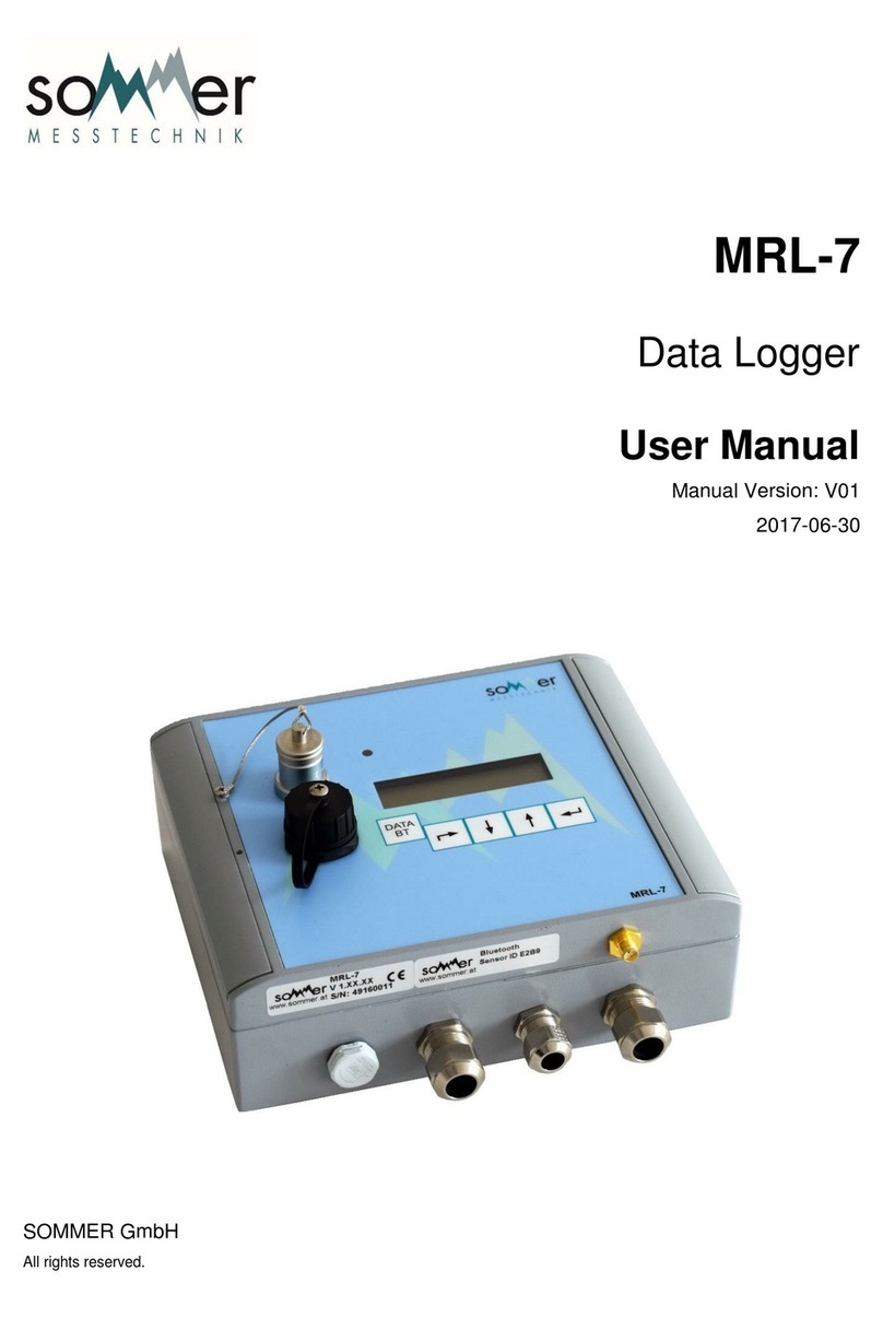
SOMMER MRL-7 User manual

MRL-7
Data Logger
User Manual
Setup version 2.14
2019-02-06
SOMMER GmbH
All rights reserved.

The Copyrights for this manual are exclusively owned by
SOMMER GmbH
A-6842 Koblach
This manual or parts of it may only be copied or passed on to third parties with written permission of SOMMER GmbH. This applies to
printed as well as digital issues of this manual.
SOMMER GmbH
Strassenhaeuser 27
6842 Koblach
Austria
http://www.sommer.at
Email: office@sommer.at
Tel.: +43 5523 / 55 989 - 0
Fax: +43 5523 / 55 989 - 19
Validity
This manual applies to the MRL-7 data logger in its varieties listed in MRL-7 versions and is valid for the
setup version 2.14 with all its subversions.
The firmware version can be viewed with the function Device status and is listed in the boot message.
Created:
Last update:
Approved:
File:
2018-11-26 jofri
2019-02-06 jofri
2018-11-26 flgra
manual_MRL-7_en.docx

CE compliance
This product is in conformity with the following standards
EN 60950-1
EN 61326-1
EN 61010
following the provision of directive R&TTE 1999/5/EC.
Image
disclaimer
All images displayed in this manual are for illustrative purposes only. The actual
product, scope of delivery or individual features may vary.

Safety information
Please read this manual carefully before installing or operating this equipment. Non-compliance with the
instructions given in this manual can result in failure or damage of the equipment or may put people at
risk by injuries through electrical or mechanic impact.
-Installation and electrical connections must be carried out by qualified personnel familiar with the
applicable regulations and standards.
-Do not perform any installations in bad weather conditions, e.g. thunderstorms.
-Maintenance and repair must be performed by trained personnel or an engineer of SOMMER Mess-
technik. Only replacement parts supplied by SOMMER Messtechnik should be used for repairs.
-Make sure that NO power is connected to the equipment during installation and wiring.
-Only use a power supply that complies with the power rating specified for this equipment.
-Keep equipment dry during wiring and maintenance.
-If applicable, it is recommended to use sensors and accessories of SOMMER Messtechnik with this
equipment.
Disposal
After this device has reached the end of its lifetime, it must not be disposed of with house-
hold waste! Instead, dispose of the device by returning it to a designated collection point
for the recycling of waste electrical and electronic equipment.
Dispose of the built-in lithium button cell and lead-acid batteries separately!

Content
1Introduction ................................................................................................................................. 7
2Unpacking .................................................................................................................................... 8
3Quick start.................................................................................................................................... 9
3.1 Communicate with the data logger ................................................................................................ 9
3.2 Configure the data logger ............................................................................................................... 9
3.3 Connect & test sensors ................................................................................................................... 9
4Specifications ............................................................................................................................. 10
4.1 MRL-7 versions.............................................................................................................................. 11
5Components & Functions............................................................................................................ 13
5.1 Measurement options .................................................................................................................. 14
5.1.1 Analog input terminals ....................................................................................................... 14
5.1.2 Counter & frequency input terminals................................................................................. 14
5.1.3 SDI-12.................................................................................................................................. 15
5.1.4 RS-485................................................................................................................................. 15
5.1.5 GPS-receiver ....................................................................................................................... 15
5.2 Sensor power supply..................................................................................................................... 15
5.3 Communication options................................................................................................................ 15
5.3.1 Direct connection to a PC ................................................................................................... 15
5.3.2 Bluetooth ............................................................................................................................ 15
5.3.3 Wireless modem................................................................................................................. 16
5.4 Data storage options..................................................................................................................... 16
5.4.1 Internal data storage .......................................................................................................... 16
5.4.2 USB flash drive.................................................................................................................... 16
5.4.3 Remote data storage .......................................................................................................... 16
6Operation................................................................................................................................... 17
6.1 How to use the keyboard.............................................................................................................. 17
6.1.1 Keyboard buttons ............................................................................................................... 17
6.1.2 Display menu ...................................................................................................................... 17
6.1.3 Activating the display.......................................................................................................... 18
6.1.4 Switching off the display..................................................................................................... 18
6.1.5 Displaying the latest measurement values......................................................................... 18
6.1.6 Replacing and adjusting a measurement value.................................................................. 18
6.1.7 Reading and changing a setting.......................................................................................... 19
6.2 How to open the housing.............................................................................................................. 20
6.3 How to connect a sensor .............................................................................................................. 21
6.3.1 Connection pins .................................................................................................................. 21
6.3.2 Using the spring clips.......................................................................................................... 23
6.4 How to set the data logger clock .................................................................................................. 24
6.5 How to copy data to a USB flash drive.......................................................................................... 24
6.5.1 Copy data since last download........................................................................................... 24
6.5.2 Copy all data ....................................................................................................................... 24
6.6 How to connect the power supply................................................................................................ 25
6.6.1 Solar power......................................................................................................................... 25
6.7 How to mount the data logger...................................................................................................... 25
6.7.1 Surge protection ................................................................................................................. 26
6.8 Maintenance ................................................................................................................................. 26

6.8.1 How to insert the SIM card................................................................................................. 26
6.8.2 How to do a modem test.................................................................................................... 27
6.8.3 How to insert the MicroSD card ......................................................................................... 28
6.8.4 How to replace the internal fuse........................................................................................ 28
6.8.5 How to replace the internal lithium battery....................................................................... 28
6.8.6 How to replace the internal lead-acid battery (MRL-7B) ................................................... 29
6.8.7 How to update the software .............................................................................................. 29
6.8.8 Calibration........................................................................................................................... 31
6.8.9 Data security....................................................................................................................... 31
7Communication.......................................................................................................................... 32
7.1 How to connect to the data logger............................................................................................... 32
7.1.1 USB to RS-232 converter .................................................................................................... 32
7.1.2 Bluetooth ............................................................................................................................ 36
7.1.3 IP-Call .................................................................................................................................. 38
7.1.4 Terminal editor ................................................................................................................... 41
7.2 How to define a station................................................................................................................. 42
8Configuration ............................................................................................................................. 43
8.1.1 How to view the data logger settings................................................................................. 43
8.2 Setting up the data logger............................................................................................................. 43
8.3 General settings ............................................................................................................................ 43
8.4 Measurement interval .................................................................................................................. 44
8.5 Data storage interval..................................................................................................................... 44
8.6 Totalizer reset options .................................................................................................................. 44
8.7 Measurement table ...................................................................................................................... 44
8.8 Messages & Actions ...................................................................................................................... 45
8.9 Telecommunication modem......................................................................................................... 45
8.10 E-Mail settings............................................................................................................................... 46
8.11 Remote connection....................................................................................................................... 47
8.12 Data logger clock........................................................................................................................... 47
8.13 Camera.......................................................................................................................................... 47
8.14 Data transmission ......................................................................................................................... 48
8.15 Serial interfaces............................................................................................................................. 48
8.15.1RS-232 interface.................................................................................................................. 48
8.15.2RS-485 interface.................................................................................................................. 49
8.15.3Serial data output ............................................................................................................... 49
8.15.4Output protocols ................................................................................................................ 49
8.15.5Commands.......................................................................................................................... 51
9Measurements & data acquisition............................................................................................... 53
9.1 Analog measurements .................................................................................................................. 53
9.1.1 Principals............................................................................................................................. 53
9.1.2 Measurement intervals ...................................................................................................... 53
9.1.3 Single ended voltage measurement................................................................................... 53
9.1.4 Differential voltage measurement ..................................................................................... 54
9.1.5 Current measurement ........................................................................................................ 54
9.1.6 Resistance measurement ................................................................................................... 54
9.2 Counter & frequency measurements ........................................................................................... 55
9.2.1 Counting events.................................................................................................................. 55
9.2.2 Frequency measurement.................................................................................................... 55
9.3 RS-485 ........................................................................................................................................... 56
9.3.1 Principals............................................................................................................................. 56
9.3.2 Operation modes................................................................................................................ 56

9.3.3 Measurement intervals ...................................................................................................... 56
9.3.4 Multiple RS-485 devices ..................................................................................................... 57
9.3.5 Managing RS-485 devices with Commander...................................................................... 57
9.3.6 Reading data from an RS-485 device.................................................................................. 57
9.3.7 Polling data from an RS-485 device.................................................................................... 58
9.4 SDI-12............................................................................................................................................ 58
9.4.1 Principals............................................................................................................................. 58
9.4.2 Measurement intervals ...................................................................................................... 59
9.4.3 Measurements with an SDI-12 sensor................................................................................ 59
9.5 GPS ................................................................................................................................................ 60
9.6 How to view live data.................................................................................................................... 60
9.7 How to collect data ....................................................................................................................... 61
9.8 How to view collected data........................................................................................................... 61
10 Parameter definition .................................................................................................................. 62
Appendix A Trouble shooting .......................................................................................................... 88
A.1 Device is not powering up............................................................................................................. 88
A.2 Data are not transmitted .............................................................................................................. 88
A.3 Commander does not find connected digital sensors .................................................................. 88
A.4 Data logger clock displays year 2050............................................................................................ 88
A.5 Camera does not record images ................................................................................................... 89
A.6 MRL-7 receives no data from RS-485 (SBP) sensors ..................................................................... 89
A.7 I receive repeated identical messages after limit violation .......................................................... 89
A.8 Measurement values are one hour behind .................................................................................. 89
Appendix B Error codes................................................................................................................... 90
B.1 Error and exception values ........................................................................................................... 90
B.2 System errors ................................................................................................................................ 90
Appendix C Serial interfaces............................................................................................................ 94
C.1 Protocols ....................................................................................................................................... 94
C.1.1 Sommer protocol ................................................................................................................ 94
C.1.2 Standard protocol............................................................................................................... 95
C.2 Commands and answers............................................................................................................... 95
C.3 Error codes.................................................................................................................................... 97
C.4 Sommer CRC-16 ............................................................................................................................ 97
Appendix D Escape characters......................................................................................................... 98
Appendix E DIP-switches ................................................................................................................ 99

7
1Introduction
The MRL-7 is a compact data logger designed to acquire, process and store all sorts of environmental
data. Its waterproof housing, integrated modem and solar charger make the MRL-7 ideal for remote,
autonomous monitoring applications. The MRL-7 is compatible with all sensors offered by SOMMER
Messtechnik and all third-party devices equipped with analog, SDI-12 or RS485 interface options.

8
2Unpacking
When unpacking your MRL-7 please make sure that the following items are present:
-MRL-7 data logger
-Set of blanking plugs (Article: 20435)
-USB-stick including Commander software and manual
The following items are available as options:
-RS-232 to USB converter cable (Article 20181)
-Antenna 2G/3G/4G (Article 21118)
-GPS-Antenna
-Camera with RS-485 communication
In case of missing or damaged items, and for additional equipment please contact your SOMMER sales
partner.

9
3Quick start
This section will guide you through the most important steps to set up a MRL-7 data logger.
3.1 Communicate with the data logger
1. Install the Commander software
2. Connect the MRL-7 to your computer using the supplied USB to RS-232 converter cable
3. Connect a 9…28 VDC power supply to the MRL-7
4. Start the Commander software and establish a connection with the MRL-7 (Section 7.1)
5. Define a station (Section 7.2)
6. Download the parameter list from the MRL (Section 8.1.1)
3.2 Configure the data logger
1. Select language and decimal character (Section 8.3)
2. Set the measurement and storage intervals (Sections 8.4 and 8.5)
3. Define the measurement variables (Section 8.7)
4. Configure the telecommunication modem and remote connection (Sections 8.9 and 8.11)
5. Set the time synchronization method (Section 8.12)
6. Define regular data transmission (Section 8.14)
7. Define the scope and structure of the data output (Sections 8.15.3 and 8.15.4)
3.3 Connect & test sensors
1. Connect analog and/or digital sensors (Sections 6.3 and 9)
2. Perform test measurements and verify units, slope and offset of the variables listed in the meas-
urement table (Section 9.5)
3. Download test data (Section 9.7)

10
4Specifications
Physical and environmental
Power supply
11.5 …28 VDC; Reverse voltage protection, overvoltage protec-
tion
Solar panel supply: max. 40 W/12 V
MRL-7B: Internal lead-acid battery: 12 V/4 Ah, deep-discharge
protected
Power consumption
Active: <23 mA @12VDC
Standby: <0.6 mA @ 12VDC
Sensor supply
100 mA @ 5V and 200 mA @ 12V
Inputs
4x Analog 0...2.5 V, 16 bit (3 single ended, 1 differential)
2x Counter (one optionally as encoder)
1x Wind speed
1x Wind direction
1x RS-485 sensor or camera input
1x SDI-12 (MRL-7 as master)
1x Manual observer input1
Outputs
3x Switch output (each approx. 500 mA @ supply voltage)
1x RS-232 (1200...115200 Baud, ASCII protocol)
1x RS-485
1x USB
1x Bluetooth
Memory
4 MB internal flash memory (equivalent to approx. 500'000 meas-
urement values)
32 GB SD-card (write only)
Measurement interval
1 s … 12 h
Mobile modem
2G, 3G (optionally 4G)
3 FTP/HTTP servers
Functions: IP call, fixed IP, time-synchronization via NTP, e-Mail
and SMS messages
Operating temperature
-30 …60 °C (-22…140 °F)
Storage temperature, humidity
-40 …60 °C (-40…140 °F), 10…90 %rH
Protection rating
IP 67
Size L x W x H
MRL-7: 180 x 150 x 60 mm (7.09 x 5.91 x 2.36 inch)
MRL-7B: 180 x 150 x 90 mm (7.09 x 5.91 x 3.54 inch)
Weight
MRL-7: 1260 g (2.78 lb)
MRL-7B: 1610 g (3.55 lb)
Table 1: Specifications
1
Has no measurement input; only accepts an offset

11
4.1 MRL-7 versions
The MRL-7 is available in seven versions:
-MRL-7-2G/3G standard version equipped with 2G/3G- modem (see Figure 1)
-MRL-7-4G-US standard version equipped with 4G/3G/2G-modem (US)
-MRL-7-4G-EU standard version equipped with 4G/3G/2G modem (EU)
-MRL-7B-2G/3G same as standard version, but with additional internal lead acid 12V/4Ah
battery (see Figure 2)
-MRL-7GPS-2G/3G same as standard version, but with integrated GPS receiver
-MRL-7B-GPS-2G/3G same as standard version, but with additional internal lead acid 12V/4Ah
battery and integrated GPS receiver
-MRL-7O same as standard version, but without telecommunication modem
Figure 1: MRL-7
Figure 2: MRL-7B

12
Figure 3: MRL-7 housing, dimensions in mm
Figure 4: MRL-7B housing, dimensions in mm

14
5.1 Measurement options
The MRL-7 data logger is designed to acquire measurements of the following sensor types:
-Analog sensor with voltage and current output
-Resistive sensors, e.g. wind vanes with potentiometer output
-Sensors with frequency output, e.g. anemometers
-Sensors with pulse output, e.g. tipping bucket rain gauge
-Digital sensors using SDI-12 and Sommer RS-485 protocols
5.1.1 Analog input terminals
The analog input terminals can be configured to different input signals. Table 2 lists the available op-
tion.
Analog input
Measurement options
An 1
0 … 2.5V
An 2
0 … 2.5V
An 3
0 … 2.5V
NTC
Resistance > 2kΩ
An 4
0 … 2.5V
0 … 0.3V
Resistance > 1k25Ω
Resistance < 1k25Ω
PT1000
Wind direction / Counter 2b
Either resistance (potentiometer) or pulse counter for encoder
(min. 5V); selected by DIP-switch (see Appendix E)
Table 2: Analog input terminals
5.1.2 Counter & frequency input terminals
The available counter and frequency inputs are listed in Table 3.
Analog input
Measurement options
Counter 1
Pulse counter (min. 5V), max. frequency 99 Hz; configurable as
pull-up or pull down (see Appendix E)
Counter 2
Pulse counter (min. 5V), max. frequency 99 Hz; configurable as
pull-up or pull down (see Appendix E)
Wind speed
Dedicated to wind speed only, max. frequency 1 kHz
Table 3: Counter & frequency input terminals

15
5.1.3 SDI-12
The MRL-7 provides one SDI-12 port. If several SDI-12 sensors are connected, their measurement data
are acquired in the order as they are listed in Measurements, table.
!
Attention
SDI-12 sensors must be supplied either externally or by a MRL-7 12V output!
They must not be operated by the switched voltage supply! For this reason 12V
sensor supply has to be set to always on.
5.1.4 RS-485
The RS-485 port of the MRL-7 provides an interface to connect digital SOMMER sensors and can be
configured to polling or pushing mode. See Section 9.3 for the polling procedure and command struc-
ture.
!
Attention
If multiple sensors are connected to the RS-485 bus and if more than one sen-
sor is talking, data communication conflicts can occur.
5.1.5 GPS-receiver
The MRL-7GPS is equipped with a GPS-receiver for moving monitoring applications, e.g. on floating
buoys. The data logger can record its position to an accuracy of <100 m and send a message if it crosses
a defined limit.
5.2 Sensor power supply
Sensors can be powered by the voltage supply terminals listed in Table 4. Please consult the sensor
manual for information on power requirements.
Output
Maximum load
5V-Out
100mA total current for all sensors
12V-Out
200mA total current for all sensors
2.5V Reference
4mA
4 x Switched 12V supplies
1 x 1.10A
3 x 0.50A
2A in total
Table 4: Voltage supply terminals
5.3 Communication options
5.3.1 Direct connection to a PC
Communication between the MRL-7 and a PC can be established with the supplied USB to RS-232 con-
verter. The Commander software or any terminal editor can be used to view and edit the data logger
settings. Among others, the Commander provides a Communication assistant to connect to the data
logger (see Section 7.1 for detailed instructions).
5.3.2 Bluetooth
A connection between the MRL-7 and your PC can also be established via Bluetooth. If your PC is
equipped with an internal or external Bluetooth-device, the Communication assistant of the Com-
mander software can connect to the data logger (see Section 7.1 for detailed instructions).

16
5.3.3 Wireless modem
The MRL-7 is equipped with a wireless UMTS-modem that uses the 2G and 3G services. This allows
remote connection with the data logger via IP-call, HTTP/FTP data transfer, e-mail and SMS-messages
as well as time synchronization via NTP.
5.4 Data storage options
5.4.1 Internal data storage
Acquired measurement data are stored in a flash memory of 4 MB, which corresponds to approx.
500'000 values. Optionally, a MicroSD card with up to 32 GB memory can be inserted into the provided
card slot. If a MicroSD card is present, data are automatically written to it once a month.
Once the internal flash memory is full, the oldest data are overwritten. No further data are written to
a full MicroSD card.
5.4.2 USB flash drive
Data stored internally can be collected on a USB flash drive. After connection to the data logger and a
keyboard command all data since the last collection are transferred to the USB flash drive. See Section
6.5 for detailed instructions.
5.4.3 Remote data storage
The acquired data stored in the data logger can be transmitted to a HTTP or FTP server. A maximum of
three servers with three different transmission intervals can be configured. At the end of each interval
all data and/or camera images since the last successful transmission are sent. See Section 8.14 for
detailed instructions.

17
6Operation
6.1 How to use the keyboard
6.1.1 Keyboard buttons
The keyboard on the data logger can be used to view data and to configure a range of settings. The
keys have the following navigation functions:
Exit the current menu / abort
Move down the menu list / decrease value
Move up the menu list / increase value
Select a menu item / confirm / trigger measurement
Searching USB stick / connect Bluetooth / special functions
If a Bluetooth connection is active, the message BT active no access! is displayed and any manual access
to data logger is denied.
!
Attention
Pressing aborts any activity on the logger, e.g. an active Bluetooth con-
nection, modem test mode or data download to USB.
6.1.2 Display menu
The settings and data that can be accessed by the keyboard on the data logger are listed in Table 5.
Start screen
Displays the station number, date and time.
* Measurements *
Menu containing the latest measurements of the variables specified in
Measurements, table.
1
Variable 1
2
Variable 2
3
Variable 3
*** Stored V ***
Menu containing the stored measurements of the variables specified in
Measurements, table.
01 … 03
Variables 1 … 3
*** Settings ***
Settings as described in Section 6.1.7
**** Status ****
Status information
1
Station No.
2
SOMMER ID
3
Station name
4
Date
5
Time

18
6
Software version
7
IMSI mobile network identification
8
State of modem
9
Type of modem
10
Mobile signal quality (CSQ)
Table 5: Display menu structure
Hint
At very low ambient temperatures the LCD Display may react slowly and en-
tered commands may not be visible instantly!
6.1.3 Activating the display
Press any key for at least one second. The data logger then displays the station number, current date
and time. After four seconds of inactivity the display automatically shows the first measurement vari-
able.
6.1.4 Switching off the display
The display is automatically switched off if no button is pressed within 10 seconds after activation.
Otherwise the display is switched off after one minute of inactivity.
Alternatively, the display can be switched off by pressing for at least two seconds. Access and
hold key! is shown and the display is switched off by holding the key.
6.1.5 Displaying the latest measurement values
After activating the data logger, press any arrow key to show the value of the first measurement vari-
able. Press the up and down keys to navigate through the measurement list.
Press to trigger a measurement of the selected variable.
6.1.6 Replacing and adjusting a measurement value
To adjust an automatically recorded value with a measurement acquired manually or with a secondary
sensor perform the following steps:
1. Navigate to the required variable as described in Section 6.1.5 above.
2. Hold for at least two seconds.
3. Enter the access code by pressing 2x followed by 2x .
4. Adjust the value with and . Hold the keys to increase/decrease the value more quickly.
5. Confirm with or abort with .
A measurement value can quickly be adjusted to zero by pressing .
!
Attention
As long as the display is active during the ongoing session, the entered access
code unlocks all system settings of the data logger!

19
6.1.7 Reading and changing a setting
The settings listed in Table 6 can be read and changed directly on the data logger by performing the
following steps:
1. Press until you get to the main menu.
2. Navigate to *** Settings *** with and and press .
3. Enter the access code by pressing 2x followed by 2x .
4. Navigate to the desired setting with and and press ..
5. Adjust the value with and . Hold the keys to increase/decrease the value more quickly.
6. Confirm with or abort with .
Setting
Example Value
Description
Station No.
20160111
Station number
Date
06.04.2017
Current date
Time
09:26:28
Current time
Exposure lock
off
Access to measurement values
Copy all data
-
Copies all internally stored data to a USB flash drive
Erase all data
-
Erases all stored data
Continuous M
turn on
Continuous Measurement
Adjust Contrast
weak
Adjusts the display contrast
Reboot Device
-
Reboots the MRL-7
Modem Testmode
-
Tests the internal mobile modem. Only available if a
modem is configured.
GPS fix
-
Stores the current Lat- and Long-coordinates perma-
nently (until next function call or data erase)
Table 6: Settings accessible on data logger
Exposure lock
Controls the access to measurement data. If active, measurement values cannot be accessed. An ex-
ception are values of the manual observer input. Also, copying data to a USB flash drive or to another
device via Bluetooth is blocked.
Copy all data
Copies all stored data to a connected USB flash drive.
Erase all data
Deletes all measurement data from the data logger.
Other manuals for MRL-7
1
Table of contents
Other SOMMER Data Logger manuals

