manuals.online logo
Brands
  1. Home
  2. •
  3. Brands
  4. •
  5. Sonance
  6. •
  7. Amplifier
  8. •
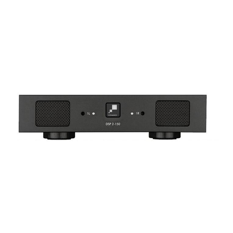
  9. Sonance DSP 2-150 MKII User manual

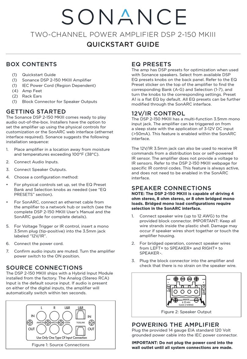
Sonance DSP 2-150 MKII User manual

SONAMP MULTI-CHANNEL POWER
AMPLIFIER WITH SonARC V2
INSTRUCTION MANUAL
DSP 2-150 MKII
1L 1R
DSP 2-150 MKII
2-R2-L
IN
OUT
1-R1-L
IN
OUT
1-LEFT
1-RIGHT
DSP 2-150 MKII
IN
OUT
BRIDGE
8 MIN
CLASS 2 WIRING
3-30 VOLTS
AC or DC
VOLTAGE TRIGGER
TCP/IP
DHCP ON-DEFAULT
CAUTION
REPLACE FUSE ONLY WITH
SAME TYPE AND RATING
ATTENTION
REMPLACER UNIQUEMENT AVEC LE
MEME TYPE ET CA LIBRE DU FUSIBLE
IR
CONTROL IR
STATUS
T5AL/250VAC
IN
OUT
MADE IN CHINA
AC 100-120V ~ 60Hz
AC 220-240V ~ 50Hz
S/N
81 WATTS
CAUTION
RISK OF ELECTRIC SHOCK
DO NOT OPEN
AVIS
RISQUE DE CHOC ELECTRIQUE
NE PAS OUVRIR
TABLE OF CONTENTS
Safety 2
Introduction/Box Contents 3
Front Panel/Rear Panel 4
$PSOLðHU3RZHU5HTXLUHPHQWV     
Connections & Volume Level Controls 7
Protection Circuitry & LEDs/Stacking 8
1HWZRUN&RQQHFWLRQ,QVWUXFWLRQV    
%DVLF6HWXS     
Advanced Setup 10
6SHFLðFDWLRQV     
$SSHQGL[$%     
Troubleshooting 17
:DUUDQW\     
1
IMPORTANT SAFETY INFORMATION
1. Read Instructions — All these safety and operating
instructions should be read before you operate the unit.
2. Retain Instructions — These safety and operating
instructions should be retained for future reference.
3. Heed Warnings — All warnings on the unit and in the
operating instructions should be adhered to.
 )ROORZ,QVWUXFWLRQV — All operating and use instructions
should be followed.
 :DWHUDQG0RLVWXUH — The unit should not be used near
water — for example, near a bathtub, washbowl, kitchen
sink, in a wet basement, or near a swimming pool, etc.
 &DUWVDQG6WDQGV — The unit should be
used only with a cart or stand that is
recommended by the manufacturer.
A unit and cart combination should be
moved with care. Quick stops, excessive
force, and uneven surfaces may cause
the unit and cart combination to overturn.
7. CAUTION: To prevent electric shock, do not use the
  VXEZRRIHUâVSRODUL]HGSOXJZLWKDQH[WHQVLRQFRUG
receptacle, or other outlets unless the blades can be
fully inserted to prevent blade exposure.
8. Ventilation — The unit should be situated so that its
location or position does not interfere with its proper
ventilation. For example, the unit should not be placed in a
built-in installation, such as a bookcase or cabinet, that may
  PTWLKL[OLÅV^VMHPYV]LY[OLIHJRWSH[L
 +HDW — The unit should be situated away from heat
sources such as radiators, heat registers, stoves, or other
appliances (including other audio components) that
produce heat.
IMPORTANT: READ ALL OF THESE INSTRUCTIONS BEFORE YOU
INSTALL OR OPERATE YOUR SUBWOOFERAND SAVETHESE
INSTRUCTIONS FOR LATER USE.
T
he
l
i
gh
tnin
g
f
la
sh
w
i
th
a
rr
o
whe
a
d
s
y
m
b
ol
,
w
i
th
i
n
an
equ
il
at
e
r
a
l
t
r
i
an
gl
e
,
i
s int
e
n
ded
to
ale
r
t
t
he
u
ser
to
t
he
presen
ce
of
u
ninsulate
d
d
an
g
erous
v
ol
ta
ge
w
i
th
i
n
t
he
pro
d
uc
t
·
s
enc
l
o
s
ur
e
t
h
a
t
ma
y
be
of
s
u
ff
icien
t
ma
g
nitu
de
to
c
on
s
t
i
tut
e
a
r
i
s
k o
f
elec
t
ric
sho
c
k
to perso
n
s
.
T
he
e
xc
l
amat
ion
point
w
i
th
in
an
equilate
r
al
t
r
iangle
is
intended
q
q
to
ale
r
t
t
he
u
ser
to
t
he
presence
of
i
mp
o
r
t
an
t
ope
r
a
t-
ing
p
p
and
maintenance
p
(se
g
r
v
icin
g)
i
n
st
r
u
ct
i
on
s
in
t
he
lite
((
r
at
ur
e
a
cco
mpa
n
yi
n
g
t
he
app
li
anc
e
.
3RZHU6RXUFHV — The unit should be connected to a
power supply only of the type described in the operating
instructions or as marked on the unit.
11. Accessories and Attachments — Only use accessories
  HUKH[[HJOTLU[ZZWLJPÄLKI`[OLTHU\MHJ[\YLY
*URXQGLQJRU3RODUL]DWLRQ — Precautions should be
taken so that the grounding or polarization means of the
unit is not defeated.
3RZHU&RUG3URWHFWLRQ — Power cords should be routed
so that they are not likely to be walked on or pinched by
items placed upon or against them, paying particular
attention to cords at plugs, convenience receptacles, and
the point where they exit from the controller.
14. Cleaning — The unit should be cleaned only as
recommended by the manufacturer.
1RQ8VH3HULRGV — The power cord of the unit should be
unplugged from the outlet when left unused for a long
period of time.
2EMHFWDQG/LTXLG(QWU\ — Care should be taken so that
objects do not fall and liquids are not spilled into the
enclosure through openings.
'DPDJH5HTXLULQJ6HUYLFH — The unit should be
 ZLY]PJLKI`X\HSPÄLKZLY]PJLWLYZVUULS^OLU!
• The power cord or the plug has been damaged.
• Objects have fallen or liquid has been spilled into the unit.
• The unit has been exposed to rain.
• The unit does not appear to operate normally or exhibits
a marked change in performance.
• The unit has been dropped or the enclosure damaged.
18. Servicing — The user should not attempt to service the
unit beyond that described in the operating instructions.
  (SSV[OLYZLY]PJPUNZOV\SKILYLMLYYLK[VX\HSPÄLK
service personnel.
This device complies with part 15 of the FCC Rules.
6WLYH[PVUPZZ\IQLJ[[V[OLMVSSV^PUN[^VJVUKP[PVUZ!
(1) This device may not cause harmful interference
(2) This device must accept any interference received,
including interference that may cause
undesired operation.
0UHJJVYKHUJL^P[O[OL,\YVWLHU<UPVU>,,,>HZ[L,SLJ[YPJHSHUK,SLJ[YVUPJ,X\PWTLU[KPYLJ[P]LLќLJ[P]L
August 13, 2005, we would like to notify you that this product may contain regulated materials which upon
disposal, according to the WEEE directive, require special reuse and recycling processing. For this reason
Sonance has arranged with our distributors in European Union member nations to collect and recycle this
WYVK\J[H[UVJVZ[[V`V\;VÄUK`V\YSVJHSKPZ[YPI\[VYWSLHZLJVU[HJ[[OLKLHSLYMYVT^OVT`V\W\YJOHZLK
this product. Please note, only this product itself falls under the WEEE directive. When disposing of packaging
and other related shipping materials we encourage you to recycle these items through the normal channels.
'630.,,
$PSOLðHU
Tested to comply
with FCC Standards for
OVTLVYVѝJL\ZLVUS`
2
Introduction
Thank you for purchasing the Sonance Sonamp DSP 2-150 MKII
HTWSPÄLY>OLUWYVWLYS`PUZ[HSSLK[OPZHTWSPÄLY^PSSNP]L`V\THU`
years of entertainment pleasure. To get the most out of your new
HTWSPÄLYWSLHZLYLHK[OPZTHU\HS[OVYV\NOS`ILMVYL`V\
begin installation.
To achieve the best performance, Sonance recommends that this
HTWSPÄLYILPUZ[HSSLKI`H:VUHUJL(\[OVYPaLK+LHSLY0UZ[HSSLY
3
Box Contents
(1) Instruction manual
1HWZRUNFRQQHFWLRQLQVWUXFWLRQV
6RQDPS'630.,,DPSOLðHU
,(&SRZHUFRUG
(4) Removable rubber feet
(2) Long rack ears

-PN\YL!:VUHTW+:742004\S[P*OHUULS7V^LY(TWSPÄLY
Unpacking
Save the carton and polystyrene inserts for future safe transport in
JHZL[OLHTWSPÄLYPZTV]LKVYYLX\PYLZZOPWWPUNMVYYLWHPY
Before proceeding with installation, locate the serial number on the
YLHYWHULSVM[OL\UP[HUKUV[LP[OLYLMVYM\[\YLYLMLYLUJL!
:5!FFFFFFFFFFFFFFFFFFFFFFFFFFFFFFFFFFFFFFFFFFFFFFFFFFFFF
Placement
7SHJL[OLHTWSPÄLYVUHSL]LSZ\YMHJLPUHU\WYPNO[WVZP[PVUV\[
of direct sunlight and away from windows through which rain
TH`LU[LY:P[\H[L[OLHTWSPÄLYH^H`MYVTOLH[ZV\YJLZZ\JOHZ
OV[HPYK\J[ZVYYHKPH[VYZ)LZ\YL[OH[[OLHTWSPÄLYPZHKLX\H[LS`
ventilated by convection or suitable cabinet fans.
5L]LYWSHJLHU`VIQLJ[VUVYHNHPUZ[[OLHTWSPÄLY
5L]LYVWLYH[L[OLHTWSPÄLYVUHJHYWL[LKZ\YMHJLHZ[OPZ^PSS
compromise ventilation.
>OLU[OLHTWSPÄLYPZPUZ[HSSLKPUHU`JHIPUL[[OLMYVU[VYIHJR
must be open during operation. Alternately, install fans in the
cabinet to assure continuous ventilation.
-PN\YL!:VUHTW+:742004\S[P*OHUULS7V^LY(TWSPÄLY9LHY7HULS
4
'630.,,)URQW3DQHO
1. Illuminated Power Button
2. Power, Active & Protection Indicator LED
3. Recessed Volume Level Control

-PN\YL!:VUHTW+:742004\S[P*OHUULS7V^LY(TWSPÄLY-YVU[7HULS
123
'630.,,5HDU3DQHO
(UHSVN0UW\[6\[*HYK393PUL0U3VVW6\[W\[Z
5. Speaker Block Connector
;YPNNLY0UW\[6\[W\[*VUULJ[VY
09*VU[YVS0U6\[
8. IR Status Light
9. RJ-45 Input
10. AC Fuse Holder
11. Power Cord Connection
59
11
67
8104
NOTE: L/R LINE IN/LOOP OUTPUT CARD CAN BE REPLACED WITH
SONANCE DIGITAL INPUT MODULE (SKU 93099 SOLD SEPARATELY) FOR
ULTIMATE PERFORMANCE ENHANCEMENT THROUGH DIRECT
CONNECTION TO A DIGITAL SOURCE.

Input/Output Lights
When each channel is active, the LED will light green as long as a
ZPNUHSPZWYLZLU[0UW\[6\[W\[3,+ZISPURPUNYLKPUKPJH[L[OH[[OL
HZZVJPH[LKJOHUULSPZILPUNV]LYKYP]LU0UW\[6\[W\[3,+Z[\YUPUN
ZVSPKYLKPUKPJH[L[OH[[OLHTWSPÄLYPZPUWYV[LJ[TVKL>OPSLPU
protect mode the LED lights will periodically light green to retest the
output to determine if the issue has been resolved. Protect mode
JV\SKILJH\ZLKI`HZOVY[PU[OL^PYLV]LYOLH[PUNVM[OLHTWSPÄLY
VYV[OLYPU[LYUHSWYVISLT^P[O[OLHTWSPÄLY
Front Panel
Power Button
;OLWV^LYI\[[VU[\YUZ[OLHTWSPÄLYVUHUKVќ>OLU[OL:VUHUJL
logo power button is engaged, the power button is illuminated
ZVSPK^OP[L;OPZTLHUZ[OLHTWSPÄLYOHZWV^LYHUKPZ[\YULK65
and ready to operate. When the Sonance logo button is slightly
KPTTLK[OLHTWSPÄLYPZPUZ[HUKI`TVKL>OLU[OL:VUHUJL
SVNVI\[[VUISPURZ^OP[L[OLHTWSPÄLYWV^LYZ\WWS`PZPU[OLYTHS
protection. In this situation, the channel LEDs will also illuminate
red, indicating that the power supply is in thermal protection mode.
NOTE: UPON INITIAL POWER UP,THERE WILL BEA 9-12 SECOND DELAY
BEFORE SOUND IS HEARD DURING THE BOOT UP CYLE.THE INDICATOR
LEDS WILL ILLUMINATE RED,THEN GREEN,THEN GO OUT.THIS IS NORMAL.
NOTE:WHEN ANY OF THE LEDS ARE RED, TURN THE AMPLIFIER OFF
IMMEDIATELY. DETERMINETHE CAUSE OF THE PROBLEM BEFORE
TURNING THE AMPLIFIER BACK ON.
Volume Level Control
,HJOJOHUULSVU[OLHTWSPÄLYOHZ]VS\TLHKQ\Z[TLU[ZJVU[YVSSLK
in the SonARC software or on the front panel recessed volume
JVU[YVSZ6\[W\[]VS\TL^PSSYLÅLJ[[OLVW[PVUSHZ[HKQ\Z[LK;OL
+:74200HTWSPÄLYZOPWZH[[OLVYTH_PT\T]VS\TL
level.
Rear Panel
Line Inputs/Loop Outputs
;OL+:74200HTWSPÄLYOHZSPULPUW\[ZHUKSVVWV\[W\[Z
;OLSVVWV\[W\[ZHYLUVUI\ќLYLK[OLTH_PT\TU\TILYVM
HTWSPÄLYZ[OH[JHUILSVVWLK[VNL[OLY^PSSKLWLUKVU[OLV\[W\[
capability of your source component
Speaker Connections
;OLYLTV]HISLISVJRJVUULJ[VYZ\ZLKVU[OL:VUHTWHTWSPÄLYZ
will accept up to 12 gauge wire. Follow the connection layout on
[OLYLHYWHULSVM[OLHTWSPÄLY4HRLZ\YLUVIHYL^PYLZJVTLPU
JVU[HJ[^P[O[OLHTWSPÄLYJOHZZPZ>OLUIYPKNPUNJOHUULSZ\ZL[OL
two outside connections on each connector. The positive wire from
the speaker should be on the left side connection and the negative
connection should be on the right side.
CAUTION: FOR CONTINUED PROTECTION AGAINST FIRE,REPLACE THE
FUSE WITH ONLY THE SAME TYPE AND RATING.
Power Cord
The Sonamp DSP 2-150 MKII features a removable power cord.
Plug the female end of the power cord into the Power Cord
*VUULJ[VYVU[OLHTWSPÄLYYLHYWHULSHUKWS\N[OLTHSLLUKPU[VH
grounded wall socket.
+656;WS\N[OLHTWSPÄLY»ZWV^LYJVYKPU[VHJVU]LUPLUJLV\[SL[
on any other audio or video component. If you need to use an
extension cord, use only a heavy duty (14 GAUGE OR LARGER)
L_[LUZPVUJVYK[VH]VPKZ[HY]PUN[OLHTWSPÄLYVM[OLJ\YYLU[
necessary for full operation.
-PN\YL!:VUHTW+:74200(TWSPÄLY-YVU[7HULS=PL^
-PN\YL!:VUHTW+:74200(TWSPÄLY9LHY7HULS=PL^

Auto On - Voltage In/Out Trigger
;OL:VUHTWHTWSPÄLYZJHUIL[\YULKVUHUKVќ\ZPUN]VS[Z
AC or DC. The Voltage Output supplies a 12 volt DC signal to
JVU[YVSHKKP[PVUHSHTWSPÄLYZVYV[OLYLX\PWTLU[;OLPUJS\KLKYLK
wire is to prevent the amp from accidentally entering sleep mode
during setup. Remove the red wire when using the voltage trigger.
IR Control
IR control is established via the 3.5mm mono mini input jack on the
YLHYVM[OLHTWSPÄLY09JVTTHUKZPUJS\KL]VS\TLT\[LNYV\W
WV^LYHUKPUW\[VW[PVUZ09JVU[YVSZNSVIHS6U6ќNYV\W]VS\TL
muting and input source selections. Connectivity can be seen with
IR status light.
IP Control
07JVU[YVSPZ]PH[OL91PUW\[07JVU[YVSZWV^LY6U6ќ]VS\TL
muting and input source selections for either global control or
group control.
AC Fuse Holder
To replace the fuse, unplug the power cord from the Power Cord
Connector and use a screwdriver to remove the fuse holder.
DSP 2-150 MKII - 5 amp AC.
Model Input Voltage Output Power (sinewave) Draw Watts 15 Amp Breaker
8[`VM(TWSPÄLYZ
20 Amp Breaker
8[`VM(TWSPÄLYZ
DSP 2-150 MKII 100-120V AC Full Power All Channels @8 ohms 371 3 5
Full Power All Channels @4 ohms 392 3 4
7V^LY(SS*OHUULSZ'VOTZ 72 20 26
7V^LY(SS*OHUULSZ'VOTZ 74 19 25
@ Idle 17
Sleep Mode 1.5
Voltage or Green Audio 0.48
Model Input Voltage Output Power (sinewave) Draw Watts 13 Amp Breaker
8[`VM(TWSPÄLYZ
20 Amp Breaker
8[`VM(TWSPÄLYZ
DSP 2-150 MKII 220-240V AC Full Power All Channels @8 ohms 359 4 5
Full Power All Channels @4 ohms 376 3 5
7V^LY(SS*OHUULSZ'VOTZ 69 20 27
7V^LY(SS*OHUULSZ'VOTZ 71 20 27
@ Idle 15
Sleep Mode 1.1
Voltage or Green Audio 0.5

3RZHULQJWKH$PSOLðHU
The Sonamp DSP 2-150 MKII features a removable IEC power
cord (see Figure 6). A 14 gauge EIA standard 120 volt grounded
WV^LYJHISLPZPUJS\KLK^P[O[OLHTWSPÄLY,HJO[PTL[OLHTWSPÄLY»Z
power cord is initially plugged in and the POWER switch is turned
65HSSJOHUULSV\[W\[ZHYLKPZJVUULJ[LKMVYHWWYV_PTH[LS` 
ZLJVUKZHUKHSS796;,*;0653,+Z^PSSPSS\TPUH[LIYPLÅ`^OPSL[OL
amp boots up.
-PN\YL!0,*7V^LY*VYK*VUULJ[PVU
IMPORTANT: DO NOT PLUG THE POWER CORD INTO THEWALL OUTLET
UNTIL ALL SYSTEM CONNECTIONS HAVE BEEN MADE AND VERIFIED.
Source Connections
6HOHFWLRQ'630.,,
There are two options when connecting audio inputs to the
+:74200HTWSPÄLYZLL-PN\YL!
Primary Line Inputs 1-L, 1-R: Use these inputs for primary
audio source.
Secondary Line Inputs 2-L, 2-R: Use these inputs for a
secondary audio source, paging or a doorbell.
$PSOLðHUV3RZHU5HTXLUHPHQWV
-PN\YL!:VUHTW+:742003LM[9PNO[3PUL0UW\[Z
-PN\YL!:VUHTW+:742004\S[P*OHUULS(TWSPÄLY7V^LY9LX\PYLTLU[Z
AC 100-120V ~ 60Hz
AC 220-240V ~ 50Hz
Plug the female end of the power cable into the Power Connector
VU[OLHTWSPÄLY»ZYLHYWHULSHUKWS\N[OLTHSLLUKKPYLJ[S`PU[VH
grounded 15 amp or 20 amp wall outlet.
IMPORTANT: DO NOT PLUG THE AMPLIFIER’S POWER CORD INTOA
CONVENIENCE OUTLET ON ANY OTHER AUDIO ORVIDEO COMPONENT.
If the electrical service is subject to frequent sags, spikes or
IYV^UV\[ZHWV^LYJVUKP[PVULYKLZPNULKMVY\ZL^P[OOPNOÄKLSP[`
LX\PWTLU[ZOV\SKILLTWSV`LK[VWYV[LJ[[OLHTWSPÄLY
CAUTION: FOR CONTINUED PROTECTION AGAINST FIRE,REPLACE THE
FUSE WITH ONLY THE SAME TYPE AND RATING WHEN NECESSARY..
7
%ULGJLQJ&KDQQHOV'630.,,
-PN\YL!=VS\TL3L]LS*VU[YVS
-PN\YL!)YPKNPUN*OHUULSZ
Volume Level Control
Volume can be controlled from the individual recessed volume level
control screws, located on the front panel and from SonARC (see
Figure 13). These volume controls balance the desired sound levels
WLYJOHUULS=VS\TLJHUILJVU[YVSSLK[OYLLKPќLYLU[^H`Z^P[O
SonARC v2 (see Figure 14).
1. Output volume 2. Turn on volume 3. Maximum volume
Output volume ranges between -70 to 12. The volume level
JVU[YVSZHYLZL[H[I`KLMH\S[
6RXUFH&RQQHFWLRQV'630.,,
On the left side of the rear panel are the audio inputs for the left
and right channels. In addition to the left and right inputs there are
also loop outputs for each channel. The loop outputs allow multiple
HTWSPÄLYZ[VZOHYLJVTTVUH\KPVZV\YJLZ;OLSVVWV\[W\[ZVU
[OLHTWSPÄLYZHYLUV[I\ќLYLK;OLU\TILYVMHTWSPÄLYZ[OH[JHU
be connected in series will depend on the output level of your audio
ZV\YJL;OLZV\YJLJVUULJ[LK[V[OL3,-;HUK90./;305,05
0UW\[ZWHZZ[OYV\NO[OL3,-;HUK90./;305,6\[W\[Z
(see Figure 12).
1 - LEFT
1 - RIGHT
BRIDGE
8ёMIN
CLASS 2 WIRING
-PN\YL!:VU(9*7HNL0U6\[:L[[PUNZ6\[W\[=VS\TL
Speaker Connections
For the best sound you should use
premium speaker wire that complies
^P[OÄYLYH[PUNJVKLZ)LZ\YL[V
check local codes governing wire
that may be installed within walls or
JLPSPUNZ:VUHTWHTWSPÄLYZHYL
stable with any reputable brand of
speaker wire or cable. The Sonamp
HTWSPÄLYZ\ZLZWLHRLYISVJR
connectors that can accommodate
up to 12 gauge wire (see Figure 9).
NOTE:ALWAYS CHECK LOCAL BUILDING CODES BEFORE INSTALLING
WIRE IN WALLS OR CEILINGS.
Figure 9
Speaker Connections

Bridging channels is accomplished using the SonARC v2 software.
6U[OLZLJVUKWHNLPU[OLZVM[^HYL\UKLY056<;:L[[PUNZNV[V
the output setup area to bridge mode and make your selections
with the drop down buttons.
<ZL[OLSLM[H\KPVPUW\[^OLUVWLYH[PUN[OLHTWSPÄLYZV\[W\[PU
bridge mode (see Figure 10).
:LSLJ[65PU[OLIYPKNLTVKLZLLÄN\YL
*VUULJ[[OLZWLHRLY»Z¸¹SLHK[V[OLSLM[ZPKLVM[OLJVUULJ[VY
THYRLK¸¹ZLL-PN\YL
*VUULJ[[OLZWLHRLY»Z¸¶¹SLHK[V[OLYPNO[ZPKLVM[OLJVUULJ[VY
THYRLK¸¹ZLL-PN\YL
5. Connect the line level audio input to the LEFT channel input on
[OLHTWSPÄLY
IMPORTANT:THE MINIMUM SPEAKER IMPEDANCE FOR BRIDGED
OPERATION IS 8 OHMS. DO NOT OPERATE A ZONE IN THE BRIDGED MODE
INTO A SPEAKER THAT IS LESS THAN 8 OHMS NOMINAL IMPEDANCE.
-PN\YL!)YPKNPUN*OHUULSZ
-PN\YL!:VUHTW+:74200
3LM[HUK9PNO[3PUL0UW\[Z6\[W\[Z
IMPORTANT: USE CAUTION WHEN SETTING VOLUME LEVELS EITHER ON
THE AMPLIFIER OR AN AUDIO SWITCHER AS NOT TO OVERDRIVE AND
POSSIBLY DAMAGE SPEAKERS.VERIFY ALL SOURCESAS OUTPUT
VOLTAGE VARIES FROM DEVICETO DEVICE.
8
IMPORTANT:ALLOWING THE AMPLIFIER TO OPERATE WITH ONE OR
MORE CHANNELS IN PROTECT MODE FOR AN EXTENDED PERIOD OF
TIME CAN DAMAGE THE AMPLIFIER.
Protection Circuitry and LEDs
;OL:VUHTWHTWSPÄLYZOH]LHT\S[PZ[HNLWYV[LJ[PVUZ`Z[LT[V
WYL]LU[KHTHNL[V`V\YHTWSPÄLYHUKZWLHRLYZ
(TWSPÄLY*OHUULS7YV[LJ[PVU+:74200
If a channel encounters a short-circuit (in bridge mode the
protection circuitry will sense a short circuit across both positive
speaker terminals), or extremely low impedance will cause the
HќLJ[LKJOHUULSV\[W\[Z[VH\[VTH[PJHSS`T\[L;OLV\[W\[VM
[OLHќLJ[LKJOHUULS^PSSYLTHPUT\[LK\U[PS[OLMH\S[OHZILLU
JVYYLJ[LK6US`[OLHќLJ[LKJOHUULSZV\[W\[^PSST\[LHSSV[OLY
channels will continue to operate normally.
(TWSPÄLY*OHUULS7YV[LJ[PVU0UKPJH[PVU+:74200
6U[OLMYVU[WHULSVM[OL:VUHTW+:74200HTWSPÄLYZHYL
dual color LEDs that illuminate to indicate the current operating
Z[H[\ZVMLHJOHTWSPÄLYJOHUULS
When the LED blinks red this is an indication that the channel is
being over driven.
>OLU[OL3,+SPNO[ZHYLZVSPKYLK[OPZPZHUPUKPJH[PVU[OLHTWSPÄLY
is in protect mode. While in protect mode the LED lights will
periodically light green to retest the output to determine if the short
has been removed. Protect mode could be caused by a short in
[OL^PYLV]LYOLH[PUNVM[OLHTWSPÄLYVYWVZZPIS`HUPU[LYUHSWYVISLT
^P[O[OLHTWSPÄLY
0M[OLHTWSPÄLYZLUZLZH]LY`SV^PTWLKHUJLVYHZOVY[VUP[Z
outputs, then it will mute its output and the protection LEDs will
turn red. The output will remain muted until the fault is cleared.
Check the rear panel block connector for shorted wire strands
or reduce the number of speakers connected in parallel to the
HTWSPÄLYV\[W\[Z:VUHUJLHTWSPÄLYZHYLYH[LKMVYHVOTSVHKVY
higher, such as two pair of eight ohm speakers.
5DFN(DU,QVWDOODWLRQ'630.,,
The DSP 2-150 MKII ships with two long rack ears for when the
HTWSPÄLYPZ[VIL\ZLKHSVULPUH<ZWHJL<UZJYL^[OLMV\Y
Phillips head screws (M4 x 0.7 pitch x 10mm long) found on each
ZPKLVM[OLSLM[HUKYPNO[MVY^HYKZLJ[PVUVMHTWSPÄLY<ZL[OLZL
ZJYL^Z[VJVUULJ[[OLPUJS\KLKYHJRLHYZ[V[OLHTWSPÄLY
(see Figure 15).
MKII
-PN\YL!9HJR,HY0UZ[HSSH[PVU+:74200
Side View Right
Front View
$PSOLðHU6WDFNLQJ
The DSP 2-150 MKII is capable of being directly stacked with the
feet removed for use in low to moderate output applications (see
Figure 16). For high-output applications, it is recommended to leave
H[SLHZ[<ZWHJLIL[^LLUHTWSPÄLYZMVYPUJYLHZLK]LU[PSH[PVU
0[PZUV[YLJVTTLUKLK[VZ[HJRTVYL[OHU[OYLLHTWSPÄLYZOPNO
without spacing.
To place two Sonamp 2-100 or DSP 2-150 MKII in a single rack
\UP[VYKLY!9HJR4V\U[)YHJRL[MVY:VUHTW+:7
MKII SKU# 93098 (see Figure 17).
MKII
MKII
MKII
1L 1R
2-100 MKII
-PN\YL!:[HJRLK*VUÄN\YH[PVU+:74200_
-PN\YL!9HJR4V\U[)YHJRL[MVY+:74200
IMPORTANT:ANY TIME THE PROTECTION CIRCUITS ARE TRIGGERED,
UNPLUG THE AMPLIFIER’S POWER CORD FROM THE WALL OUTLET
BEFORE TROUBLESHOOTING.
(TWSPÄLY7V^LY:\WWS`7YV[LJ[PVU+:74200
;OLHTWSPÄLYHSZVOHZWYV[LJ[PVUMVY[OLWV^LYZ\WWS`0M[OLWV^LY
supply heat sink temperature exceeds the design maximum, the
protection circuit will activate, disconnecting all channel outputs.
This is indicated by a blinking light on the front panel power switch.
NOTE: IF SHELF MOUNTING,ATTACH THE FOUR INCLUDED FEET BY
SCREWING THEM INTO THE THREADED OPENINGS ON THE BOTTOM
CHASSIS. NO TOOL IS REQUIRED.
Front View
Front View

Connecting to Your SonARC Homepage
;OLHTWSPÄLY»ZMHJ[VY`KLMH\S[ZL[[PUNZOHZ+/*7ZL[[V65
*VUULJ[[OLHTWSPÄLY[VHUL[^VYR^P[OHYV\[LY4HRLZ\YL[OL
JVTW\[LYHUKHTWSPÄLYHYLVU[OLZHTLUL[^VYR
;\YUVU[OLHTWSPÄLY
;OLHTWSPÄLY^PSSILPZZ\LKHU07HKKYLZZI`[OLYV\[LY
5. Use an IP scanner to determine the IP address of the Sonance
+:7HTWSPÄLYVU[OLUL[^VYR>LYLJVTTLUK-PUNHWW
for IOS, Advanced IP Scanner for Windows devices and
LanScan for macOS.
5L[^VYRKL]PJLZ^PSSZOV^\WHUK[OLHTWSPÄLY^PSSIL
named Sonance.
7. Open Safari or Chrome.
8. In the URL address window at the top, enter the IP address of
[OL:VUHUJL+:7HTWSPÄLY[VJVUÄN\YL
6RQ$5&6RIWZDUH
1HWZRUN&RQQHFWLRQ,QVWUXFWLRQV
SonARC Legend
Toggle/
3XOOGRZQ0HQX)UHH7\SH)LHOG6LQJOH$FWLRQ0HQX
(TXLSPHQW/LVW
(1) Computer or tablet
1HWZRUNURXWHUZLWK'+&3VHUYLFHHQDEOHG
5-FDEOHVRQHZKHQXVLQJZLUHOHVV
SonARC Homepage
Setup Options
@V\Y:VU(9*/VTLWHNL^PSSOH]L[^VVW[PVUZMVYZL[\W!)HZPJ
:L[\WHUK(K]HUJLK:L[\W(TWSPÄLYUHTLJHUILLU[LYLKI`
the installer.
Basic Setup Page
This page is for basic setup of EQ, source and volume. To start,
click on the Basic Setup button.
DSP Preset Assignment
Assign Preset
Click on the individual channels to show the drop down menu
of preset options. Once you locate the preset for your Sonance
speakers click on the name to set the preset. Each Sonance
+:7HTWSPÄLYOHZZSV[Z^P[OWYLJVUÄN\YLK+:7J\Y]LZMVY
Sonance speaker models pre-loaded. If the speaker model in your
HWWSPJH[PVUPZUV[VU[OLWYLSVHKLKSPZ[O\UKYLKZVM+:7ÄSLZHYL
available for download from the Sonance website. Download the
WYLZL[ÄSLMVYHKKP[PVUHS:VUHUJLZWLHRLYTVKLSZH[!
^^^ZVUHUJLJVTLSLJ[YVUPJZHTWSPÄLYZKZW
Input Source
This pull down menu allows you to select which input you would
like to assign to the channel.
Input Settings/Source Select
Input Name
;OPZPZH\ZLYLU[LYLKÄLSK^P[OHTH_PT\TVMJOHYHJ[LYZ
<ZL[OLZLÄLSKZ[VKLZJYPIL[OL[`WLVMPUW\[JVUULJ[LK
10
Output Volume (Basic Set-Up)
Play music with wide dynamics and bass that will stress
the system.
1. Start with the Output Volume for both 1L and 1R set at -30.
2. Slowly increase the volume up towards 12 and listen for
any distortion or strain from the speakers. When you hear any
distortion, reduce the volume 1 or 2 steps below this value.
3. Set this volume number for both channels. This will provide
maximum system performance and protect the speakers from
ILPUNKHTHNLKI`HTWSPÄLYJSPWWPUNHUKV]LYL_J\YZPVUVM
the woofers.
Advanced Setup Page
This page in SonARC allows you to make advanced changes to
[OL`V\YHTWSPÄLYZZL[[PUNZHUKJVUÄN\YH[PVU;VZ[HY[JSPJRVU[OL
(K]HUJLK:L[\WI\[[VUMYVT`V\Y4200»ZOVTLWHNL
IP Setup
+/*76U6Ɉ
+/*7656--PZ[OLÄYZ[VW[PVUPU07:,;<7(SS:VUHUJL+:7
ZLYPLZ HTWSPÄLYZZOPW^P[O+/*7+`UHTPJ/VZ[*VUULJ[PVU
7YV[VJVS650UTVZ[PUZ[HSSH[PVUZ+/*7ZOV\SKILSLM[65
except when you are using a control system for IP control. If you
HYLJVU[YVSSPUN[OL+:7ZLYPLZHTWSPÄLY\ZPUN07[OLU^LZ\NNLZ[
you turn DHCP OFF and use a static IP address.
The basic setup is complete!
NOTE: LEFT AND RIGHT CHANNELSARE LINKED. OUTPUTVOLUME IS
LINKED TO TURN ONVOLUME IN BASIC SETUP.
,GHQWLI\$PSOLðHU
ID Amp Mode
>OLU[OLWV^LYZ^P[JOPZ[\YULK65[OLWV^LYI\[[VUVU[OL
MYVU[VM[OLHTWSPÄLY^PSSÅHZO[VPUKPJH[L^OPJOHTWSPÄLY`V\HYL
WYVNYHTTPUN;OPZ^PSSTHRL[OLHTWSPÄLYLHZ`[VPKLU[PM`PUH
T\S[PWSLHTWSPÄLYPUZ[HSSH[PVU
Info
;OPZPZH\ZLYLU[LYLKÄLSK^P[OHTH_PT\TVMJOHYHJ[LYZ
Use this area to name your MKII.
General Settings Tab
The Advanced Setup automatically starts out on the General
Settings tab. This tab is used to set up your MKII with a network
network connection, auto on method and other basic information.t
Output Settings/Output Volume
Output Name
;OPZPZH\ZLYLU[LYLKÄLSK^P[OHTH_PT\TVMJOHYHJ[LYZ
<ZL[OLZLÄLSKZ[VKLZJYPIL[OLYVVTVYHYLH[OLJOHUULS^PSS
be powering.
IP Address
The second setting in the IP SETUP section is the IP address.
>OLU+/*7PZ65[OLJ\YYLU[07HKKYLZZ^PSSILKPZWSH`LK
To change the IP address DHCP must be set to OFF.
>OLU+/*7PZ[\YULKVќ[OL07HKKYLZZ[OH[[OLYV\[LYHZZPNULK
[V[OLHTWSPÄLY^PSSZ[PSSILHWWSPLK;OPZ07HKKYLZZPZHNVVKWSHJL
to start since it is not being used by another network device. If you
wish to change the IP address you should perform a scan of the
network and only assign an unused IP address within the range of
your router. As a general rule only change the last three digits of
[OL07HKKYLZZPU[OLHTWSPÄLYZL[[PUNZHUKVUS`HZZPNUU\TILYZ
between 2 and 254. Following this suggestion will minimize the
JOHUJLVMTHRPUN[OLHTWSPÄLYPUHJJLZZPISL
It is critical to type in the correct IP address. If the wrong IP address
PZLU[LYLK[OLHTWSPÄLYJV\SKILJVTLPUHJJLZZPISL4HRLJOHUNLZ
to the IP settings only if you fully understand network setup.
Resetting DHCP
If the IP address is not known and the amp is locked out, use the
DHCP Reset method in Appendix A.
11
Auto On
Select the Auto On method you would like to use with the blue pull
down menu. During setup it is strongly recommended that you
RLLW[OL(\[V6UTL[OVKZL[[V76>,9)<;;65[VWYL]LU[[OL
HTWSPÄLYMYVTZO\[[PUNVќ@V\JHUYL[\YUH[HU`[PTL[V[OL(\[V6U
ZL[[PUNHUKZLSLJ[[OLÄUHSTL[OVKVM(\[V6UMVY`V\YPUZ[HSSH[PVU
>OLUJVU[YVSSPUN[OLHTWSPÄLY\ZPUN07HUK09JVTTHUKZ^L
suggest using the Power Button Auto On mode. See Appendix B.
Audio
In the Audio Auto On mode, there are three sleep mode options
VќTPU\[LZOV\YZ,HJOJOHUULSOHZHUPUKLWLUKLU[ZSLLW
mode setting. The sleep mode is triggered by an audio sensing
JPYJ\P[VULHJOJOHUULSVM[OLHTWSPÄLY;OLTPUPT\TPUW\[ZLUZPUN
level is 0.5mV.
Audio Green
0U[OL(\KPV(\[V6UTVKL[OLHTWSPÄLY^PSSWV^LYVќHM[LY
minutes without an audio signal present on any of the channels.
>OLUHUH\KPVZPNUHSPZHWWSPLK[OLHTWSPÄLY^PSS[HRLHWWYV_PTH[LS`
ZLJVUKZMVY[OLHTWSPÄLY[VYLWYVK\JLH\KPVHM[LYNVPUN
[OYV\NOP[ZWV^LY\WZLX\LUJL0U[OLH\KPV(\[V65TVKL[OL
sleep function is active, see sleep mode note below. This mode
complies with EU energy saving standards.
Backup Restore
The green BACKUP and RESTORE buttons take all of the settings
VM[OLHTWSPÄLYPUJS\KPUN[OL+:7ZL[[PUNZHUKLUJHWZ\SH[LZ[OLT
PU[VVULÄSL;OPZHSSV^Z`V\[V[YHUZMLY[OLZLZL[[PUNZPU[VHUV[OLY
HTWVM[OLZHTLTVKLS^P[O[OLZHTLÄYT^HYL]LYZPVU;OPZPZH
WYVWYPL[HY`ÄSL[`WLIPUÄSLHNUVZ[PJ[V7*VY4HJ
Print
The print button will output a complete list of all settings for the
HTWSPÄLY0[PZHS^H`ZHNVVKPKLH[VRLLWHIHJR\WOHYKJVW`VM
the settings for each installation.
Power Button
When sleep mode is set to OFF the channel will be on at all times.
Use the sleep mode OFF setting for audio signals like a doorbell or
paging where audio must be reproduced immediately at any time.
Voltage
0U[OL=VS[HNL(\[V6UTVKL[OLHTWSPÄLY^PSSWV^LYVќ
immediately when the trigger voltage has been removed. When a
=(*VY+*]VS[HNLPZZLU[[V[OLHTWSPÄLYP[^PSS[HRL
ZLJVUKZMVY[OLHTWSPÄLY[VYLWYVK\JLH\KPVHM[LYNVPUN[OYV\NOP[Z
power up sequence. This mode complies with EU energy
saving standards.
Voltage Green
0U[OL=VS[HNL.YLLU(\[V6UTVKL[OLHTWSPÄLY^PSSWV^LYVќ
immediately when the trigger voltage has been removed. When a
=(*VY+*]VS[HNLPZZLU[[V[OLHTWSPÄLYP[^PSS[HRL
ZLJVUKZMVY[OLHTWSPÄLY[VYLWYVK\JLH\KPVHM[LYNVPUN[OYV\NO
its power up sequence. In Voltage Green mode the Ethernet
JVUULJ[PVUPZUV[HJ[P]L^OLU[OLHTWSPÄLYPZVќ;OPZTVKL
complies with EU energy saving standards.
IP Subnet Mask
The third setting in the IP SETUP section is the IP Subnet Mask.
This is an advanced network setup function. Under most
JPYJ\TZ[HUJLZ[OPZÄLSKZOV\SKUV[ULLK[VILLKP[LK
4HRPUNJOHUNLZPU[OPZÄLSKZOV\SKVUS`ILKVULI`HUL_WLYPLUJLK
network administrator.
ID Amp Mode
>OLU[OLWV^LYZ^P[JOPZ[\YULK65[OLWV^LYI\[[VUVU[OL
MYVU[VM[OLHTWSPÄLY^PSSÅHZO[VPUKPJH[L^OPJOHTWSPÄLY`V\HYL
WYVNYHTTPUN;OPZ^PSSTHRL[OLHTWSPÄLYLHZ`[VPKLU[PM`PUHT\S[P
amp installation.
6OHHS0RGH
:SLLWTVKLHSSV^Z`V\[VZLSLJ[OV^SVUN[OLHTWSPÄLY^PSSZ[H`
HJ[P]LHM[LY[OL(\[V65TL[OVKJLHZLZ
6Ɉ
When set in the OFF mode the channel will be on at all times.
Use the OFF setting for audio signals like a doorbell or paging
where audio must be reproduced immediately at any time.
After 15 Minutes
When an audio signal has not been present on a channel for 15
minutes, the channel will go to sleep. From the sleep state the
channel will take approximately 2-3 seconds to reproduce audio
again. This mode is similar to legacy Sonamp Auto-On operation.
After 3 Hours
When an audio signal has not been present on a channel for
3 hours, the channel will go to sleep. From the sleep state the
channel will take approximately 2-3 seconds to reproduce audio
again when audio is detected.. This mode works well for home
theater installations.
Info
;OLVYHUNLISVJRZHYLPUZ[HSSLYLU[LYLKKH[H,HJOÄLSKOHZH
maximum of 15 characters.
NOTE:WHEN AUDIO GREEN MODE IS ENABLED AND THE AMPLIFIER IS
ASLEEP, IP COMMANDS CANNOT BE RECEIVED.
12
In/Out Settings Tab
;OL056<;ZL[[PUNZ[HIPZ\ZLK[VHZZPNU`V\Y4200»ZPUW\[HUK
V\[W\[ZWLJPÄJH[PVUZ
Input Setup
Input Name
;OPZPZH\ZLYLU[LYLKÄLSK^P[OHTH_PT\TVMJOHYHJ[LYZ
<ZL[OLZLÄLSKZ[VKLZJYPIL[OL[`WLVMPUW\[JVUULJ[LK
Input Trim dB
;OPZW\SSKV^UTLU\HSSV^ZMVYPUW\[SL]LSZ[VILHKQ\Z[LKK)
This gives you the ability to level out all your inputs so when you
switch from input to input the levels will be equal. This can eliminate
HU`OHYZO[YHUZP[PVUZIL[^LLUZV\YJLZ^P[OKPќLYLU[V\[W\[
voltages. Select the pull down menu in each channel to adjust the
level trim between plus or minus 6dB in increments of 0.5dB.
Output Setup
Output Name
;OPZPZH\ZLYLU[LYLKÄLSK^P[OHTH_PT\TVMJOHYHJ[LYZ
<ZL[OLZLÄLSKZ[VKLZJYPIL[OLSVJH[PVUVM[OLZWLHRLYZ
Stereo/Mono
Allows each channel to be set for Stereo or Mono operation.
When Mono is selected, the Left and Right of the input selected will
be combined to create Mono.
DSP Preset
Apply any of the available Sonance DSP presets to each channel of
[OLHTWSPÄLYPUKLWLUKLU[S`@V\JHUHWWS`HU`VWLUWYLZL[[OLU
THRLTVKPÄJH[PVUZVU[OL,8ZL[[PUNZWHNL
Output Group
;OL+:74200OHZLPNO[V\[W\[NYV\WVW[PVUZ!(/
>OLU\ZPUN07VY09[VJVU[YVS[OLHTWSPÄLYJVTTHUKZHYLZLU[[V
HUV\[W\[NYV\WHUKUV[[VHZWLJPÄJJOHUULS
Bridge Mode
When more power is required, two channels can be bridged.
Follow the instructions on page 5, in the software, for connecting
[OL^PYLZ[OLUZLSLJ[)YPKNL65
Output Source
Source 1
This is the primary source you will direct to the speakers. Any of the
PUW\[ZH]HPSHISLVU[OLHTWSPÄLYJHUILZLSLJ[LK>OLUJOHUULSZ
are in the same output group, the inputs will all change in unison.
Left inputs default to left outputs and right inputs to right outputs.
Source 2
This is a secondary source that based on the mode Source 2
setting described below, will either override or mix with Source 1.
This input could be used for a doorbell or paging for example.
4VKL:V\YJL6Ɉ
>OLUZL[[V6--:V\YJLOHZUVLќLJ[VU[OLVWLYH[PVUVM
the channel.
Mix
When set to MIX, Source 1 and Source 2 will be blended together
when a signal is present on Source 2.
Mute
When set to MUTE, Source 1 will be muted while Source 2
is active.
Output Volume
This is the main volume level control for each channel.
When channels are placed in the same output group the levels will
change simultaneously.
Maximum Volume
IP or IR can be used to limit how loud the speakers will play in
certain areas. Output Volume and Turn On Volume can never
exceed the Maximum Volume. Maximum Volume is the highest
]VS\TLSL]LS[OH[[OLHTWSPÄLY^PSSV\[W\[;OLV\[W\[NYV\W
ZLSLJ[LKKVLZUV[HќLJ[[OPZZL[[PUN
.HPU6ɈZL[
;OLNHPUVќZL[ZL[[PUNHSSV^ZJOHUULSZPU[OLZHTLV\[W\[NYV\W
[VOH]L[OLPYSL]LSZHKQ\Z[LKPUKLWLUKLU[S`I`K);OPZPZHU
PUKLWLUKLU[ZL[[PUNUV[HќLJ[LKI`[OLV\[W\[NYV\W
Mute
The mute setting eliminates the output from the speakers.
Channels placed in the same output group will
change simultaneously.
NOTE: FRONT PANELVOLUME CONTROLS OVERWRITE THIS SETTING.
Turn On Volume
;OPZKL[LYTPULZ^OH[]VS\TLSL]LS[OLHTWSPÄLY^PSSKLMH\S[[V
when it is turned on. Channels placed in the same output group
will automatically have identical levels. Turn on volume level is
PTWSLTLU[LK^OLU[OLHTWSPÄLYPZ[\YULKVќ^P[O[OLWV^LYZ^P[JO
or goes into sleep mode.
NOTE: FRONT PANELVOLUME CONTROLS OVERWRITE THIS SETTING.
EQ Setting Tab
The EQ settings tab is used to assign your DSP EQ presets for
each channel. EQ presets provide best possible audio quality for
most Sonance speakers. EQ presets are available at
O[[W!^^^ZVUHUJLJVTLSLJ[YVUPJZHTWSPÄLYZKZW
13
Test Signal
The SonARC software includes a built in pink noise generator.
The pink noise signal can be used in conjunction with a real time
analyzer to measure speakers.
Test Signal Select
You have the option of pink noise or test signals fed into line level
inputs. Use the blue pull down menu to select between pink noise
or line level inputs as a source for the test signal.
Volume
Select your desired volume.
6U6Ɉ
;VNNSLIL[^LLUVUHUKVќ;OLWPURUVPZLZPNUHSZOV\SKUV[ILSLM[
on for more than 10 minutes to minimize the risk of damaging
the speakers.
NOTE:THE PINK NOISE GENERATOR IS AFTERTHE AUDIO SENSORY
CIRCUIT SO THE AMPWILL GO TO SLEEP DEPENDING ONTHE AUTO ON
MODE SELECTED. IF THE PINK NOISE STOPS,POWER CYCLE THEAMP.
DSP Preset Editor
Select Preset or Edit
This section allows you to edit any of the 50 existing presets.
Select the preset you want to edit from the drop down menu.
Edit Name
Edit the name of your preset with up to 15 characters.
Delete Settings
The Reset button deletes the selected preset.
Assign Preset
Output Name
These can be named Output 1L & Output 1R or room names such
as Kitchen L and Kitchen R. These are a duplicate of the output
UHTLVU[OL056<;ZL[[PUNZWHNL
DSP Preset
Select your DSP preset with the blue pull down menu. This will auto
WVW\SH[LPU[OL056<;ZL[[PUNZWHNL
Import Export
All Presets
The green IMPORT EXPORT buttons allow you to save all 50
WYLZL[ZPUVULÄSL;OPZVW[PVUJHUIL\ZLM\S^OLUZL[[PUN\W
T\S[PWSLHTWSPÄLYZ
Single Preset
The green IMPORT EXPORT buttons allow you to import or export
presets individually.
Import Single Preset
1. Import speaker preset to a location on your computer. This can
be accomplished by saving a DSP preset downloaded from
Sonance website.
2. Select the location you would like to store the new preset using
the SELECT PRESET TO EDIT pull down menu. You can save
the new preset in any of the open preset locations or you can
overwrite an existing preset you do not need.
3. Press the green IMPORT button.
4. From the pop-up menu choose local or internet.
5. You will be directed to My Computer (Windows) or Finder (MAC).
6. Find & select the new preset you would like to import (eqs).
7. You will be directed to a screen that says upload successful.
7YLZZ¸*SPJR/LYL;V.V)HJR¹
9. The preset will now be saved in the location you selected.
NOTE: PRESETS DOWNLOADED FROM INTERNET CAN TAKE UP TO 15
SECONDS TO DOWNLOAD.
Copy Preset
-YVT;V[OLIS\LW\SSKV^UTLU\ZHSSV^`V\[VW\SSHWYLZL[MYVT
one location and assign it to another location. Press green copy
button to activate.
Export Single Preset
1. Use the blue pull down menu SELECT PRESET to edit
located above the IMPORT EXPORT green buttons.
2. Select the preset you choose to export from the pull
down menu.
3. Press the green EXPORT button. Depending on your
 ^LIIYV^ZLY[OLL_WVY[LKÄSL^PSSILZH]LKPU`V\Y
downloads folder or you will be prompted where you
 ^V\SKSPRL[VZH]L[OLÄSL
2XWSXW)UHTXHQF\5HVSRQVH
;OPZNYHWOYLÅLJ[Z[OLJOHUNLZTHKLILSV^
;OL,8PTHNLZOV^Z,865H[/a[OL8PZZL[[V^P[OH
-6dB gain, creating a gradual dip in the lower midrange.
,8 ZOV^Z65H[/a[OL8PZZL[[V^P[OHK)NHPU
creating a sharp dip in the midrange.
,8ZOV^Z65H[/a[OL8PZZL[[V^P[OHK)NHPU
creating a very gradual slope in the high frequencies.
14
Parametric EQ
(SS:VUHUJL+:7HTWSPÄLYTVKLSZMLH[\YLHIHUKWHYHTL[YPJ
EQ. Adjustments made to the EQ will be displayed on the output
frequency response graph. We strongly suggest not adjusting the
EQ without proper measurement equipment.
,86U6Ɉ
;\YUZLHJOVM[OLWHYHTL[YPJ,8ÄS[LYZVUHUKVќ
EQ Frequency Hz
,U[LY[OLJLU[LYMYLX\LUJ`/aR/aMVY[OLÄS[LY[V
be adjusted.
EQ-Q
This setting determines the width of the adjustment range.
The lower the number the wider the bandwidth. The higher the
number the narrower the bandwidth.
EQ-Gain +/- dB
;OLSL]LSVMLHJOWHYHTL[YPJHKQ\Z[TLU[JHUILZL[K)
Careful adjustment of the EQ gain is necessary to prevent damage
to the speakers. Always increase the level as little as possible.
;OLÄYZ[JOVPJLZOV\SKHS^H`ZIL[VYLK\JL[OLV\[W\[[VHJOPL]L
the target frequency response.
Delay
Delay is shown in milliseconds, feet and meters. You can make an
LU[Y`PUHU`VM[OL[OYLLÄLSKZHUK[OLV[OLYÄLSKZ^PSSILJHSJ\SH[LK
automatically. The minimum delay is .01 milliseconds, the maximum
delay is 12 milliseconds. This function is useful when compensating
for distance between satellites and subwoofers for instance.
Tilt Control
The tilt controls are very sophisticated bass and treble control.
By selecting a start frequency and level you can ramp the bass and
VY[YLISL\WVYKV^U;OLLќLJ[VM[OL[PS[JVU[YVSPZ]PZPISLPU[OL
output frequency response graph.
Low Tilt/High Tilt
;OPZZL[[PUN[\YUZ[OLSV^HUKOPNO[PS[JVU[YVSZVUHUKVќ
Frequency
Enter the start frequency of the tilt in Hz. To boost the low
frequencies you would typically set the low tilt to 100Hz. To boost
the high frequencies you would set the high tilt to around 5kHz.
Gain
;OLNHPUJHUILZL[PUK)Z[LWZK)>OLUZL[[PUN[OLNHPU
use as little positive gain as possible to minimize the risk of damage
to the loudspeakers.
Crossover
LP Xover / HP Xover
;OPZZL[[PUN[\YUZ[OLOPNOHUKSV^WHZZJYVZZV]LYZVUHUKVќ
Frequency
0U[OPZÄLSK`V\JHULU[LYHU`MYLX\LUJ`IL[^LLU/aR/a
Filter Type
K)K)K)HUKK)WLYVJ[H]L)\[[LY^VY[OÄS[LYZHYL
available in the pull down menu. The higher the number the faster
the speakers output will be reduced below or above the crossover
frequency. In a typical satellite subwoofer system the crossover
frequency would be around 80-100Hz for both the high and low
WHZZÄS[LYZ
All of the above output power ratings are when connected to an 8
Ohm load.
No Limiter -3dB -6dB -9dB
4200 150 watts 75 watts 37.5 watts 18.25 watts
Limiter
The limiter operates as a brick wall limit on the output of the
HTWSPÄLY;OLSPTP[LYKYVWKV^UTLU\OHZK)K)HUKK)
VW[PVUZ;OLTH_PT\TV\[W\[ZMVYLHJOVM[OLTVKLSZ!

6SHFLðFDWLRQV
621$03'630.,,
5\TILYVM*OHUULSZ 2 (1 stereo pair)
Power Output - 8 ohms (Stereo) 150 Watts RMS per channel (all channels driven)
Power Output - 4 ohms (Stereo) 224 Watts RMS per channel (all channels driven)
Power Output - 8 ohms (Bridged) 473 Watts
-YLX\LUJ`9LZWVUZL /a¶R/aIHUK^PK[OSPTP[LK
Total Harmonic Distortion 0.07% (1kHz, 8 ohms) 0.06% (1kHz, 4 ohms)
:PNUHS[V5VPZL9H[PV K)/aR/a
Input Gain 29dB
Input Sensitivity 100mV for 1 Watt Output @8 ohms
1230mV for 150 Watts Output @8 ohms
Input Impedance 20k ohms
Loop Output Impedance 600 ohms
Maximum Source Input Voltage 2.9V VAC RMS
*VTT\UPJH[PVU7YV[VJVS ;*70791)HZL;
Power Consumption 120V AC
@8 ohms (sinewave, full power) 371 Watts (all channels driven)
@4 ohms (sinewave, full power) 392 Watts (all channels driven)
 'VOTZZPUL^H]LWV^LY >H[[ZHSSJOHUULSZKYP]LU
 'VOTZZPUL^H]LWV^LY >H[[ZHSSJOHUULSZKYP]LU
@Idle 17 Watts
@IP or IR standby 1.5 Watts
@Standby 0.48 Watts
Power Consumption 220V AC
@8 ohms (sinewave, full power) 359 Watts (all channels driven)
@4 ohms (sinewave, full power) 376 Watts (all channels driven)
 'VOTZZPUL^H]LWV^LY  >H[[ZHSSJOHUULSZKYP]LU
 'VOTZZPUL^H]LWV^LY >H[[ZHSSJOHUULSZKYP]LU
@Idle 15 Watts
@IP or IR standby 1.1 Watts
@Standby 0.5 Watts
Heat Output
@8 ohms (sinewave, full power) 242 BTU (all channels driven)
@4 ohms (sinewave, full power) 314 BTU (all channels driven)
 'VOTZZPUL^H]LWV^LY );<HSSJOHUULSZKYP]LU
 'VOTZZPUL^H]LWV^LY );<HSSJOHUULSZKYP]LU
AC Voltage 100-120V@60Hz, 220-240V@50Hz
AC Fuse 5A (T5-AL)
9HJR:WHJL9LX\PYLTLU[ <¶9HJR>PK[O
+PTLUZPVUZ^-LL[>_/_+ ¹_¹_¹ TT_TT_TT
+PTLUZPVUZ^9HJR,HYZ^V-LL[>_/_+    ¹_¹_¹TT_TT_TT
Shipping Weight 11 lbs (5.0kg)
*(+-PSLZH]HPSHISLMVYKV^USVHKH[^^^ZVUHUJLJVTLSLJ[YVUPJZHTWSPÄLYZKZW
Dim White Power Button (TWSPÄLYPZWS\NNLKPUHUKPUZ[HUKI`TVKL
)YPNO[>OP[L7V^LY)\[[VU  (TWSPÄLYPZHJ[P]L
Power Button Blinking The amp is in ID Amp Mode (see page 9).
Green LED Signal is present (>1.0mv) on channel.
Blinking Green Signal is going above and below the active level or between songs.
Blinking Red The channel is being over driven.
Solid Red The amp is in protection mode (see page 6).
Power Button Blinking Light Amp temperature exceeds the design maximum.
3,+»Z)SPURPUN9LK
:[LW ;\YUHTWSPÄLYVќ
Step 2 With light pressure adjust 1L Volume Control full counter clockwise.
Step 3 With light pressure adjust 1R Volume Control full clockwise.
:[LW    7V^LYVUHTWSPÄLY^HP[MVY7V^LY)\[[VU[VZOV^HZLYPLZVMÅHZOLZ
:[LW ;\YUHTWSPÄLYVќ
Step 6 Set the 1L Volume Control full clockwise or at desired volume level.
:[LW    7V^LYVUHTWSPÄLY
LED Indicator Explanation
DHCP Reset Step DHCP Reset Steps

APPENDIX A
(TWSPÄLY-HJ[VY`9LZL[ (TWSPÄLY-HJ[VY`9LZL[:[LWZ
Step 1 0UH<93HKKYLZZ^PUKV^LU[LY[OLHTWSPÄLYZ07HKKYLZZ^P[O[OLL_[LUZPVU<WKH[LO[T
       L_ <WKH[LO[T
Step 2 6U[OL\WKH[LWHNLSVJH[L[OLYLKYLZL[I\[[VU<ZL[OPZI\[[VU[VJVTWSL[LS`YLZL[[OLHTWSPÄLY
Step 3 9L[\YU[V[OL/VTL7HNL[VZL[\W[OLHTWSPÄLY5V[L!,8WYLZL[Z^PSSUV[ILKLSL[LK
Auto On Setting Sleep Mode Options Time To Music Ethernet
(\KPV 6Ɉ (S^H`ZVU (S^H`ZVU
(\KPV 4PU ZLJVUKZ (S^H`ZVU
(\KPV /YZ ZLJVUKZ (S^H`ZVU
Auto On Setting Sleep Mode Options Time To Music Ethernet
7V^LY)\[[VU 6Ɉ (S^H`ZVU (S^H`ZVU
7V^LY)\[[VU 4PU ZLJVUKZ (S^H`ZVU
7V^LY)\[[VU /YZ ZLJVUKZ (S^H`ZVU
APPENDIX B
+:74200(TWSPÄLY(\[V6U:SLLW4VKL+L[HPSZ
Auto On Setting Sleep Mode Options Time To Music Ethernet
(\KPV.YLLU 5VUL ZLJVUKZ ;\YUZVɈHM[LYTPUZ^P[OV\[H\KPV
Auto On Setting Sleep Mode Options Time To Music Ethernet
=VS[HNL 5VUL ZLJVUKZ (S^H`ZVU
Auto On Setting Sleep Mode Options Time To Music Ethernet
=VS[HNL.YLLU 5VUL ZLJVUKZ ;\YUZVɈHM[LYTPUZ^P[OV\[]VS[HNL
17
Out of the Box Troubleshooting
No Power
Front panel Power LED does not illuminate when AC cord is
plugged into an outlet and the amp is switched on.
Cause:
AC cable is improperly seated either at the back of the amp or
at the AC outlet.
:VS\[PVUZ!
࠮Verify that both ends of the power cable are securely seated.
Cause:
There is no AC current at the outlet.
:VS\[PVUZ!
࠮Securely insert the AC cord into another known-working
AC outlet.
Cause:
$UHDUSDQHOIXVHLVEORZQ
:VS\[PVUZ!
࠮Check the rear panel fuse and replace if blown. If the front panel
power LED still does not illuminate, contact Dana Innovations
Technical Support for additional instructions.
No Audio
Front panel Power LED illuminates but the amp will not pass audio.
Cause:
Current selected source is not transmitting an audio signal
into the amp.
:VS\[PVUZ!
࠮Verify that the source is powered on, operating and not in a muted
or paused state.
Cause:
$XGLRLQWHUFRQQHFWFDEOHVDUHQRWSXVKHGLQVHFXUHO\DWWKH
VRXUFHDWWKHSUHDPSDQGRUDWWKHDPSâVLQSXWFRQQHFWRUV
:VS\[PVUZ!
࠮With the amp powered of, carefully reseat each of the RCA
 JVUULJ[PVUZH[[OLZV\YJLH[[OLWYLHTWaVULJVU[YVSSLYHUKH[
the input of the Sonamp.
Cause:
The line level interconnect cables are defective.
:VS\[PVUZ!
࠮Substitute another interconnect cable for the source to preamp
HUKVYWYLHTW[V:VUHTW
Cause:
7KHVSHDNHUZLUHVDWHLWKHUWKHRXWSXWRIWKHDPSRUDWWKH
speaker location are not securely connected.
:VS\[PVUZ!
࠮Reattach the speaker wires on the 4-terminal speaker block
connectors on the rear panel of the Sonamp.
Cause:
7KHDPSâVSRZHUPDQDJHPHQWRSWLRQVWDWHLVQRWEHLQJPHW
(amp is set to voltage trigger and is not receiving a voltage).
:VS\[PVUZ!
࠮=LYPM`YLZL[[OLWV^LYTHUHNLTLU[VW[PVU[Vº7V^LY)\[[VU»
Cause:
The SonARC bridging option is engaged but the speakers are
QRWZLUHGSURSHUO\IRUEULGJHPRGH
:VS\[PVUZ!
࠮Set the bridge mode to OFF. If audio output is still unavailable,
contact Dana Innovations Technical Support.
No IP Control
Ethernet connection is made but IP control is not responding.
Cause:
Faulty ethernet cable.
:VS\[PVUZ!
࠮*OLJR[OLYLHYWHULSUL[^VYR3,+ZVU[OLPUW\[JHYKHYLÅHZOPUN
to indicate network connectivity. If these LEDs are not active,
replace the Ethernet cable. If the network LEDs are active but the
DSP amp will not respond, perform the network reset as
described below and retest.
Cause:
)DXOW\QHWZRUNVZLWFK
:VS\[PVUZ!
࠮Connect the amp directly to the network router, bypassing the
network switch.
Cause:
7KHDPSâV,3DGGUHVVLVLPSURSHUO\VHW
:VS\[PVUZ!
࠮:JHU[OLUL[^VYRÄUK[OL+:7HTW»Z07HKKYLZZHUKLU[LYP[
into your web browser. SonARC set-up software should populate,
showing the DHCP network address assigned to the amp by the
YV\[LY0U[OL(K]HUJLK:L[[PUNZ[HIPU:VU(9*[\YUVќ+/*7
HUKZL[[OLÄ_LK07HKKYLZZVM`V\YJOVVZPUN,U[LY[OPZ07
address in your IP control module. Test the system with your
control devices (touchscreens, iPhones with app, etc.).
࠮If the LEDs are still inactive and the other network devices are
working properly, then the input card may need to be replaced,
contact Dana Innovations Technical Support. If the network LEDs
are active but the DSP amp will not respond, perform the network
reset as described below and retest.
No IR Control
;OL09V\[W\[MYVT[OLJVU[YVSZ`Z[LTPZJVUULJ[LK[V[OLº09
*VU[YVS0UW\[»QHJRVM[OL+:7HTW^P[OHTVUVTPUPJHISLUV[H
stereo mini cable) but the amp will not respond to IR commands.
Cause:
The DSP amp does not respond to IR commands using the
PRQRPLQLLQSXWMDFN
:VS\[PVUZ!
࠮Test the IR sending component by plugginga mini-emitter into its
output and using the emitter to control a local AV component
Z\JOHZH+=+WSH`LYVY(=YLJLP]LY=LYPM`[OH[[OLº09:[H[\Z»
LED near the IR Control Jack illuminates when an IR command is
sent, indicating that the Amp is receiving the signal.
࠮If the local AV component can be controlled by the mini-emitter,
[OLU[OLWYVISLTTH`ILJH\ZLKI`V\[KH[LKÄYT^HYL9LX\LZ[
[OLSH[LZ[ÄYT^HYLMYVT+HUH0UUV]H[PVUZ;LJOUPJHS:\WWVY[
Factory Reset
Perform a factory reset procedure on the DSP amp using a small
ÅH[OLHKQL^LSLYZZJYL^KYP]LY
:VS\[PVUZ!
࠮With the amp powered OFF, carefully rotate the front panel
accessed 1L volume control fully-counterclockwise and rotate the
1R volume control to fully-clockwise.
࠮7YLZZ[OLWV^LYZ^P[JO[V[\YU[OLHTW65
࠮Wait approximately 20 seconds for the reset to complete--power
switch LED on continuously.
࠮Turn the amp OFF.
࠮Reset the 1L volume control to maximum.
࠮;\YU[OLHTW65
For additional support, contact Dana Innovations Technical Support
www[email protected].
Channel Out
One channel of the amp does not have output.
Cause:
/LQHOHYHOLQWHUFRQQHFWFDEOHIURPWKHVRXUFHWRWKHDσHFWHG
amp channel is loose, disconnected or faulty.
:VS\[PVUZ!
࠮Verify that the interconnect cables are properly seated at both
the amp end inputs and source end outputs. Disconnect both
interconnects on the amp end (1L and 1R input connections on
the amp).
࠮*VUULJ[[OLM\UJ[PVUPUNJOHUULS»ZJHISLMYVT[OLZV\YJL[V[OL
 UVUM\UJ[PVUPUNJOHUULS»ZPUW\[QHJRVU[OLHTWMVYL_HTWSLPM
 3PZMH\S[`JVUULJ[9»ZJHISL[V[OL3PUW\[QHJRHUK[LZ[
࠮Test playback to see if the speaker connected to the non-
functioning channel works.
࠮0M[OLHќLJ[LKJOHUULSPZUV^^VYRPUN[OLWYVISLTJV\SKIL^P[O
that channel at the source or with the interconnect cable for the
non-functioning channel.
࠮9LWSHJL[OLHќLJ[LKJOHUULS»ZPU[LYJVUULJ[JHISLHUKYL[LZ[
 ;LZ[ZV\YJLVUHUV[OLYH\KPVZ`Z[LT[VJVUÄYTJOHUULSV\[W\[Z
are functioning.
Cause:
6SHDNHUZLUHOHDGLQJRXWWRWKHFKDQQHOLVORRVHGLVFRQQHFWHG
or faulty.
:VS\[PVUZ!
࠮Verify proper connection of the speaker wire at amp end
and speaker end. If the channel is still inoperative, disconnect
the speaker wire from the non-functioning channel at both the
amp end and speaker end. Connect a new, test speaker wire
 MYVT[OLHќLJ[LKHTWJOHUULSV\[W\[[V[OLZWLHRLYVY[VHUL^
 [LZ[ZWLHRLY0M[OLHќLJ[LKJOHUULSPZUV^^VYRPUN[OLWYVISLT
must be the speaker wire; replace with a new speaker wire. If the
 HќLJ[LKJOHUULSPZZ[PSSUV[^VYRPUN[OLHќLJ[LKJOHUULSPU[OL
amp could be defective; contact DI Technical Support for
next steps.
Protection LEDs are Illuminated
One or more red protection LEDs are on.
Cause:
7KHSUREOHPFRXOGEH'&RQWKHLQSXWRIWKHDPSOLðHU
$VKRUWRQWKHVSHDNHUZLUHJRLQJRXWWRWKH]RQH
A short at the speaker itself.
:VS\[PVUZ!
࠮Disconnect the speaker wire from that channel going out to
the zone.
࠮If the protection LED goes out, connect your local test speaker,
turn the amp back on and play music.
࠮If the test speaker produces sound, then the speaker wire leading
out to the zone or at the zone speaker is shorted.
࠮0M[OL[LZ[ZWLHRLYKVLZUV[WYVK\JLZV\UKHUK`V\»]L[YPLKH
KPќLYLU[ZV\YJLVU[OH[WHPYVMHTWJOHUULSZ[VY\SLV\[H
defective source, then the amp requires service; contact Dana
Innovations Technical Support for additional instructions.
18
©2018 Sonance. All rights reserved.
Sonance is a registered trademarks of Dana Innovations.
+\L[VJVU[PU\V\ZWYVK\J[PTWYV]LTLU[HSSMLH[\YLZHUKZWLJPÄJH[PVUZHYLZ\IQLJ[[VJOHUNL^P[OV\[UV[PJL
-VY[OLSH[LZ[:VUHUJLWYVK\J[ZWLJPÄJH[PVUPUMVYTH[PVU]PZP[V\Y^LIZP[L!^^^ZVUHUJLJVT
:65(5*, *HSSL(THULJLY:HU*SLTLU[L*( <:(
   -(?!  ;LJOUPJHS:\WWVY[!   
www.sonance.com 11.12.18
/,0,7('7:2<($5:$55$17<
:VUHUJL^HYYHU[Z[V[OLÄYZ[LUK\ZLYW\YJOHZLY[OH[[OPZ:VUHUJLIYHUKWYVK\J[WYVK\J[^OLUW\YJOHZLKMYVTHUH\[OVYPaLK:VUHUJL
+LHSLY+PZ[YPI\[VY^PSSILMYLLMYVTKLMLJ[P]L^VYRTHUZOPWHUKTH[LYPHSZMVY[OLWLYPVKZ[H[LKILSV^:VUHUJL^PSSH[P[ZVW[PVUHUKL_WLUZL
during the warranty period, either repair the defect or replace the Product with a new or remanufactured Product or a reasonable equivalent.
EXCLUSIONS
TO THE EXTENT PERMITTED BY LAW, THE WARRANTY SET FORTH ABOVE IS IN LIEU OF, AND EXCLUSIVE OF, ALL
OTHER WARRANTIES, EXPRESS OR IMPLIED, AND IS THE SOLE AND EXCLUSIVE WARRANTY PROVIDED BY SONANCE.
ALL OTHER EXPRESS AND IMPLIED WARRANTIES, INCLUDING THE IMPLIED WARRANTIES OF MERCHANTABILITY,
IMPLIED WARRANTY OF FITNESS FOR USE, AND IMPLIED WARRANTY OF FITNESS FOR A PARTICULAR PURPOSE ARE
SPECIFICALLY EXCLUDED.
5VVULPZH\[OVYPaLK[VTHRLVYTVKPM`HU`^HYYHU[PLZVUILOHSMVM:VUHUJL;OL^HYYHU[`Z[H[LKHIV]LPZ[OLZVSLHUKL_JS\ZP]LYLTLK`
HUK:VUHUJL»ZWLYMVYTHUJLZOHSSJVUZ[P[\[LM\SSHUKÄUHSZH[PZMHJ[PVUVMHSSVISPNH[PVUZSPHIPSP[PLZHUKJSHPTZ^P[OYLZWLJ[[V[OL7YVK\J[
IN ANY EVENT, SONANCE SHALL NOT BE LIABLE FOR CONSEQUENTIAL, INCIDENTAL, ECONOMIC, PROPERTY, BODILY
INJURY, OR PERSONAL INJURY DAMAGES ARISING FROM THE PRODUCT, ANY BREACH OF THIS WARRANTY OR
OTHERWISE.
;OPZ^HYYHU[`Z[H[LTLU[NP]LZ`V\ZWLJPÄJSLNHSYPNO[ZHUK`V\TH`OH]LV[OLYYPNO[Z^OPJO]HY`MYVTZ[H[L[VZ[H[L:VTLZ[H[LZKVUV[
allow the exclusion of implied warranties or limitations of remedies, so the above exclusions and limitations may not apply. If your state does
UV[HSSV^KPZJSHPTLYVMPTWSPLK^HYYHU[PLZ[OLK\YH[PVUVMZ\JOPTWSPLK^HYYHU[PLZPZSPTP[LK[VWLYPVKVM:VUHUJL»ZL_WYLZZ^HYYHU[`
@V\Y7YVK\J[4VKLSHUK+LZJYPW[PVU!:VUHTW+:742004\S[P*OHUULS7V^LY(TWSPÄLY
>HYYHU[`7LYPVKMVY[OPZ7YVK\J[!;^V`LHYZMYVT[OLKH[LVU[OLVYPNPUHSZHSLZYLJLPW[VYPU]VPJLVYV[OLYZH[PZMHJ[VY`WYVVMVMW\YJOHZL
(KKP[PVUHS3PTP[H[PVUZHUK,_JS\ZPVUZMYVT>HYYHU[`*V]LYHNL!;OL^HYYHU[`KLZJYPILKHIV]LPZUVU[YHUZMLYHISLHWWSPLZVUS`[V[OLPUP[PHS
installation of the Product, does not include installation of any repaired or replaced Product, does not include damage to allied or associated
equipment which may result for any reason from use with this Product, and does not include labor or parts caused by accident, disaster,
ULNSPNLUJLPTWYVWLYPUZ[HSSH[PVUTPZ\ZLLNV]LYKYP]PUN[OLHTWSPÄLYVYZWLHRLYL_JLZZP]LOLH[JVSKVYO\TPKP[`VYMYVTZLY]PJLVYYLWHPY
^OPJOOHZUV[ILLUH\[OVYPaLKI`:VUHUJL6I[HPUPUN(\[OVYPaLK:LY]PJL!;VX\HSPM`MVY[OL^HYYHU[``V\T\Z[JVU[HJ[`V\YH\[OVYPaLK
:VUHUJL+LHSLY0UZ[HSSLYVYJHSS:VUHUJL*\Z[VTLY:LY]PJLH[   ^P[OPU[OL^HYYHU[`WLYPVKT\Z[VI[HPUHYL[\YUTLYJOHUKPZL
number (RMA), and must deliver the Product to Sonance shipping prepaid during the warranty period, together with the original sales
receipt, or invoice or other satisfactory proof of purchase.

Other Sonance Amplifier manuals

Sonance SUB 10-250D User manual

Sonance

Sonance SUB 10-250D User manual

Sonance Navigator Harbor User manual

Sonance

Sonance Navigator Harbor User manual

Sonance SYMPHONY S622C User manual

Sonance

Sonance SYMPHONY S622C User manual

Sonance SONAMP DSP 2-150 User manual

Sonance

Sonance SONAMP DSP 2-150 User manual

Sonance SONAMP 2-100 User manual

Sonance

Sonance SONAMP 2-100 User manual

Sonance SONAMP ASAP1D User manual

Sonance

Sonance SONAMP ASAP1D User manual

Sonance Sonamp DSP 2-750 MKII User manual

Sonance

Sonance Sonamp DSP 2-750 MKII User manual

Sonance Sonamp 875D SE User guide

Sonance

Sonance Sonamp 875D SE User guide

Sonance SONAMP ASAP3D SE User manual

Sonance

Sonance SONAMP ASAP3D SE User manual

Sonance SONAMP 1250 MKII User manual

Sonance

Sonance SONAMP 1250 MKII User manual

Sonance SONAMP 275 SE User manual

Sonance

Sonance SONAMP 275 SE User manual

Sonance DSP 2-750 MKIII User manual

Sonance

Sonance DSP 2-750 MKIII User manual

Sonance SR 2-125 User manual

Sonance

Sonance SR 2-125 User manual

Sonance SONAMP Sonamp 1230 User manual

Sonance

Sonance SONAMP Sonamp 1230 User manual

Sonance SONAMP 275X3 SE RMF User manual

Sonance

Sonance SONAMP 275X3 SE RMF User manual

Sonance DSP 8-130 MKII SONAMP User manual

Sonance

Sonance DSP 8-130 MKII SONAMP User manual

Sonance Sonamp 875D SE User manual

Sonance

Sonance Sonamp 875D SE User manual

Sonance DSP 2-150 MKIII User manual

Sonance

Sonance DSP 2-150 MKIII User manual

Sonance SONAMP A150 User manual

Sonance

Sonance SONAMP A150 User manual

Sonance SONAMP ASAP3D SE User manual

Sonance

Sonance SONAMP ASAP3D SE User manual

Sonance 8-50 User manual

Sonance

Sonance 8-50 User manual

Sonance BBE User manual

Sonance

Sonance BBE User manual

Sonance DSP 2-150 MKIII Installation instructions

Sonance

Sonance DSP 2-150 MKIII Installation instructions

Sonance SONAMP 275 SE User manual

Sonance

Sonance SONAMP 275 SE User manual

Popular Amplifier manuals by other brands

Lucoro Broadcast FMAMP250 manual

Lucoro Broadcast

Lucoro Broadcast FMAMP250 manual

Audio Alchemy PPA-1 owner's manual

Audio Alchemy

Audio Alchemy PPA-1 owner's manual

Vantage Controls Axium 450 Series instruction manual

Vantage Controls

Vantage Controls Axium 450 Series instruction manual

PCB Piezotronics 426M11 Installation and operating manual

PCB Piezotronics

PCB Piezotronics 426M11 Installation and operating manual

Hitachi HA-3700 Service manual

Hitachi

Hitachi HA-3700 Service manual

RCS AUDIO-SYSTEMS MAX-104 operating instructions

RCS AUDIO-SYSTEMS

RCS AUDIO-SYSTEMS MAX-104 operating instructions

maxon motor ADS_E 50/5 operating instructions

maxon motor

maxon motor ADS_E 50/5 operating instructions

Blonder tongue BTEA-CO-B16-116-SA user manual

Blonder tongue

Blonder tongue BTEA-CO-B16-116-SA user manual

FONESTAR MA-680RGUZ instruction manual

FONESTAR

FONESTAR MA-680RGUZ instruction manual

RDL FLAT-PAK FP-PA35A manual

RDL

RDL FLAT-PAK FP-PA35A manual

Harman Kardon HK250 instruction manual

Harman Kardon

Harman Kardon HK250 instruction manual

Crown CL4 Architectural & engineering specifications

Crown

Crown CL4 Architectural & engineering specifications

SDI HPDA-100RM-C operating manual

SDI

SDI HPDA-100RM-C operating manual

DYNACO PAS-4 owner's manual

DYNACO

DYNACO PAS-4 owner's manual

OCEAN CONTROLS KTA-200 quick start guide

OCEAN CONTROLS

OCEAN CONTROLS KTA-200 quick start guide

WILSON PRO ENTERPRISE 1300 installation guide

WILSON PRO

WILSON PRO ENTERPRISE 1300 installation guide

Audioplex IR BOOOSTER installation manual

Audioplex

Audioplex IR BOOOSTER installation manual

MyTek Liberty DAC II owner's manual

MyTek

MyTek Liberty DAC II owner's manual

manuals.online logo
manuals.online logoBrands
  • About & Mission
  • Contact us
  • Privacy Policy
  • Terms and Conditions

Copyright 2025 Manuals.Online. All Rights Reserved.