3. The cutout for all Original Series Large Round speakers is
101
/8” (257mm). There also must be at least 6” (152mm)
depth within the ceiling cavity for the speaker.
4. Position the included cutout template where the speaker is to
be located and pencil an outline on the ceiling.
• If you are unsure about obstructions, drill a small hole in
the center of the outline and insert a coat hanger wire into
the hole to feel-around for possible obstructions.
5. Cut the hole using a drywall saw, and run the speaker wires.
6;<)44)<176
Sonance Original Series Large speakers feature exclusive FastMount®
tabs and an integral Roto-Lock® mounting system for quick mounting
directly into existing ceilings and walls.
1. Remove the paint plug from the speaker. Connect the speaker wire to
the terminals on the speaker. Double-check that you connected amplifi-
er + to speaker + and amplifier – to speaker –.
2. Make sure all the clamps are in the full clockwise position so that they
are tucked within the mounting hole’s border. Insert the speaker into the
hole in the ceiling. The Roto-Lock® system can accommodate a maxi-
mum ceiling material thickness of 1¼” (32 mm).
Wa R n i n G : t h e e d G e s o f t h e fa s t M o u n t ta b s
aRe veRy shaRp. use caution When handlinG
t h e s p e a k e R .
• The FastMount tabs will prevent the speaker from falling out of the
mounting hole, allowing the installer to let go of the speaker to pick-
up tools or other items (see
Figure 5
).
7<- "0- );<7=6< <)*; ):- ,-;1/6-, .7: 76-<15- =;-
764@.<0-;8-)3-:1;:-57>-,.:75<0-57=6<16/074-<0-
);<7=6<<)*;?144,1;+766-+<)6,:-5)1616;1,-<0-?)44
3. Tighten the four screws on the front of the speaker baffle. The Roto-Lock
clamps will automatically rotate into position and begin clamping the
speaker (see
Figure 5
).
• When you notice resistance on the screws the speaker has
been clamped successfully.
587:<)6<4?)@;=;-47?<7:9=-;-<<16/;$ 7>-:<1/0<-6
4. Attach the grille after the speaker has been installed. Insert about half
of the grille into the groove at the edge of the speaker. Gently fit the
remaining half of the grille by working around the speaker, fitting the
grille into the groove as you go.
7<- '7= +)6 ),2=;< <0- <7:9=- )8841-, <7 <0- 7<77+3
;+:-?;<7)+01->-)8:78-:/:144-.1<
Painting The Speakers and Grilles
You can paint the speakers and grilles before installing them, which will
eliminate the “paint scar” if the speaker ever needs to be removed for ser-
vice. You can also paint the speakers after installation, but before the
grilles are attached. All Original Series Large speakers come from the fac-
tory fitted with a plastic “paint plug”. Use the paint plug to protect the
speaker drivers while the flange is being painted along with the wall.
Sonance always suggests painting the grille separately from the speaker.
Before painting, carefully remove the under-grille cloth. It is held in place
with a light tacking glue that makes it easy to remove.
Spray the grilles with thinned paint (5 parts thinner to 1 part paint), being
careful not to plug the holes. Too heavy a coat of paint on the grille will
adversely affect the sound of the speaker.
Once the grilles and flange are painted and dry, replace the under-grille
cloth, remove the paint plug from the speaker flange and install the grille.
Speaker Adjustments
1>7<16/%77.-:)6,!761+@-A
All Original Series Large speakers have a pivoting woofer assembly and
a pivoting Sonic Eye® (midrange-tweeter assembly). These pivoting dri-
vers allow you to direct sound toward or away from the listening area.
If you’re using the speakers in stereo or as the front L/C/R speakers in a
home theater, pivot the woofer and/or Sonic Eye directly towards the lis-
tening area. This can be especially helpful if the speakers are widely-sep-
arated and the music fails to blend into a central sonic image.
If you’re using the speakers as surround channel speakers in a home the-
ater, you can create a more diffuse, spacious surround effect by aiming
the woofers and/or Sonic Eye towards a wall or window, away from the
listeners.
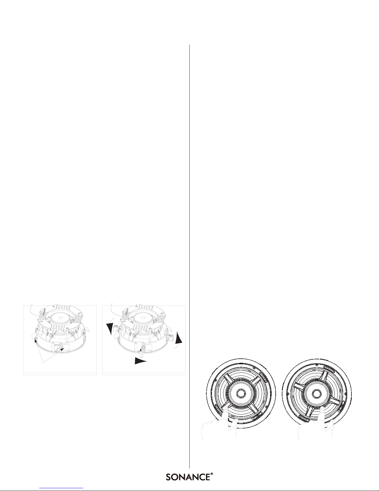
-(3-11'$--%$/
Apply pressure on the outer edge of the Sonic Eye support bracket, as
shown below in
Figure 6
. Do not touch or apply pressure to the woofer
cone.
Figu e 5: O iginal Se ies La ge Installation
ORIGINAL SERIES LARGE ROuNd SPEAKERS
Figu e 6: Pivoting the Woofe and Sonic Eye