manuals.online logo
Brands
  1. Home
  2. •
  3. Brands
  4. •
  5. Sonance
  6. •
  7. Speakers
  8. •
  9. Sonance PROFESSIONAL MKII Series User manual

Sonance PROFESSIONAL MKII Series User manual

1
PROFESSIONAL SERIES SURFACE MOUNT MKII
MANUAL
2
TABLE OF CONTENTS
2 Product Description
2 Box and Contents
3 Product Features
4 Product Preparation
4 Amplifier Selection
4 Wire Selection
4 70V/100V System
4 8 ohm System
4 Speaker Placement
4 Pivoting the Speaker
5 Grille and Speaker Shell Painting
6 Installation
8 Technical Specifications
8 PS-S43T MKII
9 PS-S53T MKII
10 PS-S63T MKII
10 PS-S83T MKII
11 PS-S83WT MKII
12 Certifications and Safety Agency
12 Technical Assistance and Service
13 Warranty
IMPORTANT SAFETY INSTRUCTIONS
This product is intended to be installed by professional
AV integrators and installers only. This product manual
is intended to serve as a general guideline for most
applications. It is the installer’s responsibility to ensure
this product is installed in accordance with local
building codes and regulations. Consult a local authority
for specific requirements, regulations, and building
codes of the jurisdiction in which this product is to be
installed.
READ THIS DOCUMENT IN ITS
ENTIRETY BEFORE ATTEMPTING USE.
1. Read these instructions.
2. Keep these instructions.
3. Heed all warnings.
4. Follow all instructions.
5. Clean only with a dry cloth.
6. Do not block any ventilation openings. Install in
accordance with the manufacturer’s instructions.
7. Do not install near a heat source such as radiators,
heat registers, stoves, fireplaces, or other apparatus
(including amplifiers) that produce heat.
8. Only use attachments/accessories specified by
Sonance.
9. To be installed in indoor locations only.
10. Refer all servicing to qualified service personnel.
SURFACE MOUNT
PS-S43T MKII | PS-S53T MKII | PS-S63T MKII |
PS-S83T MKII | PS-S83WT MKII
Scan QR code for additional
information and resources. For
technical support call (949) 492-
7777 or visit www.sonance.com/
professionalseries
BOX CONTENTS
2-WAY SPEAKERS
(2) PS-S43T MKII, or PS-S53T MKII, or PS-S63T MKII,
or PS-S83T MKII
(2) Speaker Grille
(2) FastMount Brackets
(2) Wiring Terminal Covers
(2) Speaker Connectors
WOOFER
(1) PS-S83WT MKII
(1) Speaker Grille
(1) FastMount Bracket
(1) Wiring Terminal Cover
(1) Speaker Connector
3
Paintable Shell (white only)
Rotation Lock
Cable Pass-Through
FastMount Bracket
Powder Coated Aluminum Grille
High Excursion Woofer
Chambered Tweeter
(excludes PS-S83WT)
Tuning Port
Transformer Tap and Bypass Selector
Euroblock Connector with Loop
Through
PRODUCT FEATURES
4
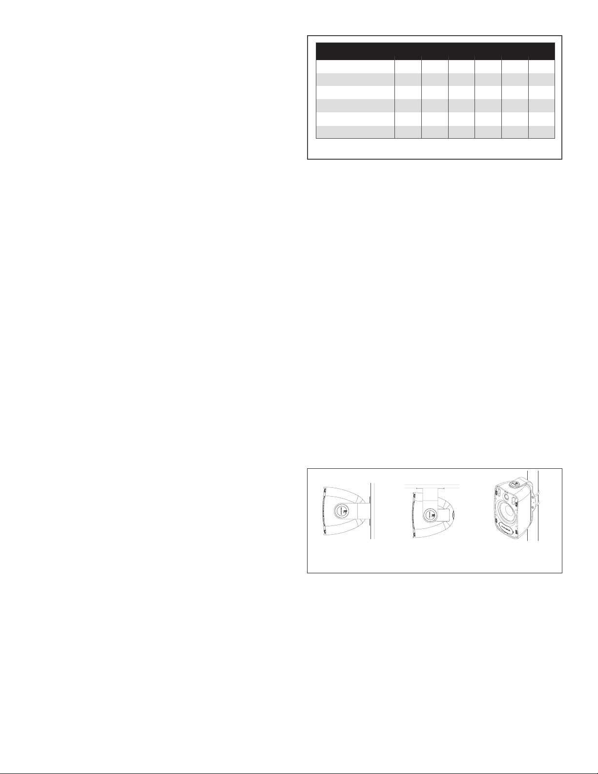
WIRE RESISTANCE IN OHMS VS. LENGTH OF CABLE RUN
20 GAUGE
50’ 100’ 150’ 200’ 250’ 300’
.86 1.73 2.59 3.45 4.32 5.18
.65 1.30 1.94 2.59 3.24 3.89
.43 .85 1.28 1.71 2.14 2.56
.27 .54 .81 1.08 1.35 1.62
.17 .34 .51 .68 .85 1.02
DISTANCE IN FEET
18 GAUGE
16 GAUGE
14 GAUGE
12 GAUGE
PIVOTING THE SPEAKERS
You can rotate the speaker in the bracket to direct the
sound towards the listeners.
1. Unlock the slide locks on the speaker pivots by
moving them towards the rear of the speaker.
2. Rotate the speakers to the desired position.
3. Lock the slide locks by moving them towards the front
of the speaker.
WALL/CEILING MOUNTING
It is important that the bracket is securely mounted onto
a structurally sound surface, capable of withstanding
the weight of the product and any vibration created
by the operation of the speaker. Four screws points
must be used at all times. A screw size of #14 to #20
diameter x 2” length or M6 to M8 diameter x 50mm
length is recommended. When mounting onto drywall
or plasterboard, the bracket should be axed to a joist
or stud. When mounting onto brick or concrete, wall
plugs or concrete anchors should be used. Install a safety
cable from one of the 1/4-20 UNC threaded holes on the
back of the speaker to a secure location on the adjoining
mounting surface (hardware not included). Optional
compatible third party mounts: OmniMount 15.0C and
OmniMount 15.0W.
POLE MOUNTING
To mount the speaker on a pole, two U-bolts and nuts
should be used to clamp around the pole and bolt through
the four holes on the back of the FastMount bracket.
Spring washers or blue thread lock are recommended to
ensure the nuts do not work loose through the vibration
of the speaker.
Wall Mount Ceiling Mount Pole Mount
Figure 2: Mounting
Figure 1: WIRE RESISTANCE
PRODUCT DESCRIPTION
Sonance Professional Series includes a range of In-Ceiling,
Pendant and Surface Mount Speakers that deliver true full
range fidelity, extremely low distortion, wide dispersion
and a smooth power response. The range also shares
consistent voicing, ensuring seamless sonic integration
when used together throughout a space. Surface Mount
MKII Speakers feature Sonance’s FastMount® bracket
and front cable connection to speed up the installation
process and provide a clean appearance. Available in 4”,
5.25”, 6.5” and 8” 2-Way and 8” Woofer in either black or
white.
AMPLIFIER SELECTION
When choosing an amplifier the maximum number of
speakers and the output level of each speaker must be
known. The sum of the tap settings should never exceed
80% of the amplifier’s rated output. For example, if there
are 5 speakers and the taps are set at 15 watts, the load
would be 75 watts (5 x 15 watts = 75 watts). To arrive at
the needed power for this number of speakers, simply
divide the total load by 0.8. In this case, 75/0.8 = 93.75
watts. A standard 100 watt amp would safely drive this
load. To calculate the amount of usable power an amp
oers, simply multiply the rated output by 0.8, i.e., 100
watts x 0.8= 80 watts.
WIRE GAUGE – 70V/100V SYSTEM
The most common wire used on commercial 70 volt
systems is 18 gauge, 2 conductor, stranded, and jacketed
without a shield. The wire starts at the amplifier location
and is paralleled at each speaker location. Wire length
using 18 gauge is appropriate up to 700 feet with a
100 watt load. If you double the load (sum of your tap
settings), you will reduce the footage by half, to 350
feet. Conversely, if you halve the load, you may double
the acceptable wire length, i.e., a 50 watt load is safe
over 1400 feet of 18 gauge. Stepping up to 16 gauge
wire extends the allowable run length by approximately
35%. For example, a 100 watt load can go 700 feet on 18
gauge; the same load may be placed on 1,100 feet of 16
gauge.
WIRE GAUGE – 8 OHM SYSTEM
The total wire resistance should be less than 10% of the
speaker impedance in an 8 Ohm system. The speakers
are nominally 8 Ohms impedance, so your total wire
resistance should be no more than 8 Ohms. The extra
resistance from the wire will have a very negative aect
on the sound quality of the speaker. The sound can
be less dynamic, definition of bass frequencies can be
reduced, and in extreme cases, the high frequencies can
be attenuated. Amplifier power is also wasted in the wire,
reducing the maximum output level of the system. Please
refer to the following chart (see Figure 1) when deciding
on the appropriate wire gauge for your installation.
SPEAKER PLACEMENT
The FastMount mounting system makes it easy to mount
the speakers in a variety of positions and locations (see
Figure 2).
5
1. Remove the speakers from the mounting brackets by
pulling the tabs on the front panels outward and away
from each other (see Figure 4).
2. Run the speaker wires from the amplifier to the
speaker locations and through the holes in the
mounting brackets.
NOTE: BE SURE TO LEAVE ENOUGH WIRE AT THE
SPEAKER LOCATION TO FEED THROUGH THE TUNNEL
IN THE SPEAKER ENCLOSURE AND WIRE TO THE
EUROBLOCK CONNECTOR ON THE FRONT.
3. Attach the mounting bracket to the mounting surface
using hardware (not included) that is appropriate
for the type of surface. Stainless hardware is
recommended.
4. If the installation requires that the speakers be
mounted on poles you can attach the bracket to poles
using 2.5” U-bolts (not included, see figure 5).
5. Feed the speaker wires from the brackets into the
wire entry grommets on the backs of the speakers,
through the wire tunnels and out the openings on the
speakers’ front panels (see Figure 6 and 7).
• The grommet forms a water-resistant seal around the
speaker wire.
• Make sure there is enough slack in the wire to allow
the speaker to pivot on the bracket.
PAINTING THE GRILLES AND SPEAKER
Sonance Professional Series Surface Mount MKII speakers
feature a tough polypropylene enclosure that can be
painted. Sonance recommends using a weather-resistant
outdoor paint and a spray gun.
1. If they have already been installed, remove the grilles
from the speakers.
2. To protect the speaker driver units during painting,
place the grilles on a piece of cardboard and trace
around their outlines. Then cut the cardboard just
inside of the trace line and fit these “paint plugs” into
the speakers’ baes. Be careful not to damage the
driver components while fitting the paint plugs.
3. Paint the speakers the desired color according to the
paint manufacturer’s instructions. Remove the paint
plugs after the paint has thoroughly dried.
4. Paint the grille separately from the speaker using very
thin paint (5:1 ratio). Avoid plugging the grille holes
with excess paint.
INSTALLING THE SPEAKERS
The best performance is obtained by placing the left and
right speakers at ear level, 6–10ft apart. The speakers
should be facing the listening area. If you are mounting
the speakers above or below ear level, pivot them up or
down to direct the sound towards the listeners.
Figure 4: Surface Mount Bracket Removal
Figure 5: Attaching Bracket
Figure 6: Wire Entry Grommet
BRACKET CARRYING CAPACITY
PS-S43T
KGS
2.81
3.63
4.88
7.02
POUNDS
6.19
8.00
10.76
15.48
MODEL
PS-S53T
PS-S63T
PS-S83T | PS-S83WT
Figure 3: Bracket Carrying Capacity
6. Slide the speakers onto the brackets until the locks
snap into place (see Figure 7).
NOTE: BE SURE THAT THE BRACKET CLIPS SNAP
COMPLETELY INTO PLACE TO PREVENT ANY
BLOCKAGE WITHIN THE SPEAKER PERIMETER WHERE
6
9. Determine the proper
wattage setting for each
speaker in the installation
and set each speaker’s
transformer tap selector
(see Figure 10).
FITTING THE TERMINAL COVER
Fit the wiring terminal covers into the recesses in the
speakers’ front panels (see Figure 11). The covers should fit
tightly, but can be removed and replaced if the speakers
need to be disconnected.
Parallel Connection To Next SpeakerFrom Power Amplifier
Loop Thru Connection To Next SpeakerFrom Power Amplifier
Parallel Connection To Next SpeakerFrom Power Amplifier
Loop Thru Connection To Next SpeakerFrom Power Amplifier
7. Connect the wires from your amplifier to the input
connector.
8. Strip approximately 0.1875” (5mm) of the insulation
o each wire. Insert the wire into the correct square
opening on the connector. Use a small flat head
screwdriver to tighten the corresponding screw to
secure the wire.
When using multiple speakers you can connect the
speakers either in parallel or in the loop through method
as shown (see Figure 8 and 9).
From Power Amplifier To Next Speaker
Figure 7: Attach Speakers to Brackets
Figure 8: Parallel Connection
Figure 9: Loop Thru Connection
Figure 10: Transformer Tap
THE GRILLE IS TO BE INSERTED. PULL ON THE FRONT
OF THE CABINET TO ENSURE THE CLIPS ARE FULLY
SEATED AND THAT THE BRACKET IS SECURE.
Pull enough wire through the front of the speaker to allow
connection to the terminals.
SETTING TRANSFORMER TAP SWITCH
Sonance Professional Series Surface Mount MKII speakers
are factory set for maximum output when used with a
Sonamp DSP 2-750 MKII or another 70V/100V amplifier.
No additional work is necessary if the speakers are
operating in 70V or 100V and can run at their full volume
capacity. Applications for changing the tap switch from
factory default:
• Speakers are to be installed in sensitive areas and
need to be “tapped down” for lower volume
• More speakers are needed to be added to a 70V/100V
amplifier already operating at full capacity
• A small zone is to be driven by an 8 Ohm amplifier
8 OHM TAP SETTINGS
Aligning the values on the dial with the arrow indicators
on either side to the “8 Ohm” setting is eective for 8
Ohm amplifier connections.
70V TAP SETTINGS
Align the arrow positioned with the 70V values to the
desired wattage setting. Turning the dial one click stop in
either direction increases or decreases the speaker’s input
power.
100V TAP SETTINGS
Align the arrow positioned with the 100V values to the
desired wattage setting. Turning the dial one click stop in
either direction increases or decreases the speaker’s input
power.
Figure 11: Attach the Connector Cover
7
FITTING AND REMOVING THE GRILLE
1. When installing the grille, align the grille trim skirt
with the groove in the enclosure.
2. To lock the grille in place apply pressure at the
locations of the four grille retention clips. An audible
click should be heard as the grille locks into place.
Figure 12: Pushing the Grille into Place
Figure 13: Removing the Grille
NOTE: To remove the grille, we suggest starting in any
one of the four corners using a grille pulling tool (not
included). Once the grille is pulled out past the retention
clip in one corner, the remainder of the grille can be
removed by working your hand around and lightly
pulling outward, being careful not to bend the grille
skirt. If the grille skirt does become bent during removal,
it can be straightened by carefully bending it back into
its original shape.
8
INCLUDED ACCESSORIES
Euroblock Connector x 2
FastMount Bracket x 2
Terminal Cover x 2
Grille x 2
OPTIONAL ACCESSORIES
PS-S43T MKII Replacement Grille White (PR) | 40209
PS-S43T MKII Replacement Grille Black (PR) | 40210
PS-S43T MKII TECHNICAL SPECIFICATIONS
Black Part # 40199 (EA)
White Part # 40200 (EA)
Frequency Range (-10dB) 57Hz–25kHz
Frequency Range (-3dB) 75Hz–20kHz
Power Capacity 60 Watts Continuous Program Power, 30 Watts Continuous Pink Noise
Nominal Sensitivity 87dB
Nominal Coverage Angle 90° x 90° coverage
Directivity Factor (Q) 7.6
Directivity (DI) 8.1dB
Rated Maximum SPL 105dB @ 1 meter (3.3 feet) average, 110dB peak
Rated Impedance 8 Ohms nominal, 6 Ohms minimum
Transformer Taps 70V: 30W, 15W, 7.5W and 3.8W; 100V: 30W, 15W and 7.5W
Crossover Point 3000Hz
Overall Dimensions (WxHxD) 5.47” x 9.25” x 4.8” (139mm x 235mm x 122mm)
Product Weight 6.79 lbs (3.08kg) /Each
Shipping Weight 19 lbs (8.62kg) /Pair
Unit of Measure Each
LF Driver 4” (100mm) Polypropylene Cone, Butyl Rubber Surround
HF Driver 1” (25mm) Cloth Dome, Ferrofluid cooled
Color Black or White
Grille Powder Coated Aluminum, Friction Fit
Input Connectors Front-mounted four pin, Euroblock with loop output connections
Mounting Bracket Aluminum U-Bracket with Sonance FastMount
Environmental and UV Conforms to MIL-STD-810 for humidity, salt spray, temperature,
IEC 529 IPX4 splash-proof rating
Safety Agency UL-1480, UL-2043, CSA-C22.2 No.205, NFPA-70, and NFPA-90A
9
INCLUDED ACCESSORIES
Euroblock Connector x 2
FastMount Bracket x 2
Terminal Cover x 2
Grille x 2
OPTIONAL ACCESSORIES
PS-S53T MKII Replacement Grille White (PR) | 40211
PS-S53T MKII Replacement Grille Black (PR) | 40212
PS-S53T MKII TECHNICAL SPECIFICATIONS
Black Part # 40201 (EA)
White Part # 40202 (EA)
Frequency Range (-10dB) 43Hz–25kHz
Frequency Range (-3dB) 70Hz–20kHz
Power Capacity 90 Watts Continuous Program Power, 45 Watts Continuous Pink Noise
Nominal Sensitivity 88dB
Nominal Coverage Angle 90° x 90° coverage
Directivity Factor (Q) 7
Directivity (DI) 8dB
Rated Maximum SPL 106dB @ 1 meter (3.3 feet) average, 113dB peak
Rated Impedance 8 Ohms nominal, 6 Ohms minimum
Transformer Taps 70V: 30W, 15W, 7.5W and 3.8W; 100V: 30W, 15W and 7.5W
Crossover Point 2750Hz
Overall Dimensions (WxHxD) 6.36” x 10.08” x 5.68” (162mm x 256mm x 144mm)
Product Weight 8.68 lbs (3.94kg) /Each
Shipping Weight 23.93 lbs (10.85kg) /Pair
Unit of Measure Each
LF Driver 5.25” (130mm) Polypropylene Cone, Butyl Rubber Surround
HF Driver 1” (25mm) Cloth Dome, Ferrofluid cooled
Color Black or White
Grille Powder Coated Aluminum, Friction Fit
Input Connectors Front-mounted four pin, Euroblock with loop output connections
Mounting Bracket Aluminum U-Bracket with Sonance FastMount
Environmental and UV Conforms to MIL-STD-810 for humidity, salt spray, temperature,
IEC 529 IPX4 splash-proof rating
Safety Agency UL-1480, UL-2043, CSA-C22.2 No.205, NFPA-70, and NFPA-90A
10
INCLUDED ACCESSORIES
Euroblock Connector x 2
FastMount Bracket x 2
Terminal Cover x 2
Grille x 2
OPTIONAL ACCESSORIES
PS-S63T MKII Replacement Grille White (PR) | 40213
PS-S63T MKII Replacement Grille Black (PR) | 40214
PS-S63T MKII TECHNICAL SPECIFICATIONS
Black Part # 40203 (EA)
White Part # 40204 (EA)
Frequency Range (-10dB) 49Hz–25kHz
Frequency Range (-3dB) 65Hz–20kHz
Power Capacity 120 Watts Continuous Program Power, 60 Watts Continuous Pink Noise
Nominal Sensitivity 88dB
Nominal Coverage Angle 90° x 90° coverage
Directivity Factor (Q) 6.5
Directivity (DI) 7.9dB
Rated Maximum SPL 108dB @ 1 meter (3.3 feet) average, 116dB peak
Rated Impedance 8 Ohms nominal, 6 Ohms minimum
Transformer Taps 70V: 60W, 30W, 15W and 7.5W; 100V: 60W, 30W and 15W
Crossover Point 2750Hz
Overall Dimensions (WxHxD) 7.51” x 12.14” x 6.86” (191mm x 308mm x 174mm)
Product Weight 11.43 lbs (5.18kg) /Each
Shipping Weight 31.26 lbs (14.18kg) /Pair
Unit of Measure Each
LF Driver 6.5” (165mm) Polypropylene Cone, Butyl Rubber Surround
HF Driver 1” (25mm) Cloth Dome, Ferrofluid cooled
Color Black or White
Grille Powder Coated Aluminum, Friction Fit
Input Connectors Front-mounted four pin, Euroblock with loop output connections
Mounting Bracket Aluminum U-Bracket with Sonance FastMount
Environmental and UV Conforms to MIL-STD-810 for humidity, salt spray, temperature,
IEC 529 IPX4 splash-proof rating
Safety Agency UL-1480, UL-2043, CSA-C22.2 No.205, NFPA-70, and NFPA-90A
11
INCLUDED ACCESSORIES
Euroblock Connector x 2
FastMount Bracket x 2
Terminal Cover x 2
Grille x 2
OPTIONAL ACCESSORIES
PS-S83T MKII Replacement Grille White (PR) | 40215
PS-S83T MKII Replacement Grille Black (PR) | 40216
PS-S83T MKII TECHNICAL SPECIFICATIONS
Black Part # 40205 (EA)
White Part # 40206 (EA)
Frequency Range (-10dB) 41Hz–25kHz
Frequency Range (-3dB) 55Hz–20kHz
Power Capacity 160 Watts Continuous Program Power, 80 Watts Continuous Pink Noise
Nominal Sensitivity 90dB
Nominal Coverage Angle 90° x 90° coverage
Directivity Factor (Q) 7.6
Directivity (DI) 8.1dB
Rated Maximum SPL 110dB @ 1 meter (3.3 feet) average, 116dB peak
Rated Impedance 8 Ohms nominal, 6 Ohms minimum
Transformer Taps 70V: 60W, 30W, 15W and 7.5W; 100V: 60W, 30W and 15W
Crossover Point 2750Hz
Overall Dimensions (WxHxD) 9.01” x 14.02” x 8.58” (229mm x 356mm x 218mm)
Product Weight 14.72 lbs (6.68kg) /Each
Shipping Weight 42.23 lbs (19.16kg) /Pair
Unit of Measure Each
LF Driver 8” (203mm) Polypropylene Cone, Butyl Rubber Surround
HF Driver 1” (25mm) Cloth Dome, Ferrofluid cooled
Color Black or White
Grille Powder Coated Aluminum, Friction Fit
Input Connectors Front-mounted four pin, Euroblock with loop output connections
Mounting Bracket Aluminum U-Bracket with Sonance FastMount
Environmental and UV Conforms to MIL-STD-810 for humidity, salt spray, temperature,
IEC 529 IPX4 splash-proof rating
Safety Agency UL-1480, UL-2043, CSA-C22.2 No.205, NFPA-70, and NFPA-90A
12
INCLUDED ACCESSORIES
Euroblock Connector x 1
FastMount Bracket x 1
Terminal Cover x 1
Grille x 1
OPTIONAL ACCESSORIES
PS-S83T MKII Replacement Grille White (PR) | 40215
PS-S83T MKII Replacement Grille Black (PR) | 40216
PS-S83WT MKII TECHNICAL SPECIFICATIONS
Black Part # 40207 (EA)
White Part # 40208 (EA)
Frequency Range (-10dB) 32Hz–300kHz
Frequency Range (-3dB) 50Hz–150kHz
Power Capacity 200 Watts Continuous Program Power, 125 Watts Continuous Pink Noise
Nominal Sensitivity 89dB
Nominal Coverage Angle 90° x 90° coverage
Rated Maximum SPL 110dB @ 1 meter (3.3 feet) average, 116dB peak
Rated Impedance 8 Ohms nominal, 6 Ohms minimum
Transformer Taps 70V: 120W, 60W, 30W and 15W; 100V: 120W, 60W and 30W
Crossover Point 150Hz
Overall Dimensions (WxHxD) 9.01” x 14.02” x 8.58” (229mm x 356mm x 218mm)
Product Weight 16.08 lbs (7.62kg) /Each
Shipping Weight 21.49 lbs (9.75kg) /Each
Unit of Measure Each
LF Driver 8” (203mm) Polypropylene Cone, Butyl Rubber Surround
Color Black or White
Grille Powder Coated Aluminum, Friction Fit
Input Connectors Front-mounted four pin, Euroblock with loop output connections
Mounting Bracket Aluminum U-Bracket with Sonance FastMount
Environmental and UV Conforms to MIL-STD-810 for humidity, salt spray, temperature,
IEC 529 IPX4 splash-proof rating
Safety Agency UL-1480, UL-2043, CSA-C22.2 No.205, NFPA-70, and NFPA-90A
13
CERTIFICATIONS
SAFETY AGENCY COMPLIANCE
Sonance Professional Series loudspeakers models
PS-S43T MKII, PS-S53T MKII, PS-S63T MKII, PS-S83T MKII
and PS-S83WT MKII meet the following standards:
UL 1480: Listed Standard For Safety For Speakers for
Fire Alarm, Emergency, Commercial and Professional Use.
NFPA 70: 2002 National Electrical Code
Environmental AND UV: Conforms to Mil Spec 810 for
humidity, salt spray, temperature, IEC 529 IP-X4 splash-
proof rating.
TECHNICAL ASSISTANCE AND
SERVICE
The Technical Assistance Department at Sonance is
available at (949) 492-7777 to answer any questions
concerning the operation and installation of your speakers
between the hours of 7:00 AM and 5:00 PM Pacific time,
Monday through Friday, except holidays.
In the event your unit should need repair or service, you
may return the unit to your authorized dealer or use the
following guidelines:
Please keep original packaging when possible.
1. Be prepared to state the model number and / or serial
number, date of purchase, and dealer’s name and
address when calling.
2. Contact Sonance directly at (949) 492-7777 or at
www.sonance.com
YOU MUST HAVE PRIOR AUTHORIZATION TO RETURN
YOUR UNIT.
3. If you are returning the product directly to Sonance,
call us to obtain a return authorization number before
shipping.
4. Ship the product via United Parcel Service, Federal
Express, or other package delivery service. Please do
not use the U.S. Postal Service.
Write the Return Authorization Number on the shipping
label. Do not write it on the outside of the box.
Ship to:
Attn: Quality Assurance Department
Sonance
11016 Mulberry Ave
Fontana, CA 92337
14
LIMITED FIVE (5) YEAR WARRANTY
Sonance warrants to the first end-user purchaser that this Sonance-brand product (“Product”), when purchased from
an authorized Sonance Dealer/Distributor, will be free from defective workmanship and materials for the period stated
below. Sonance will at its option and expense during the warranty period, either repair the defect or replace the Product
with a new or re-manufactured Product or a reasonable equivalent.
EXCLUSIONS
TO THE EXTENT PERMITTED BY LAW, THE WARRANTY SET FORTH ABOVE IS IN LIEU OF, AND EXCLUSIVE OF,
ALL OTHER WARRANTIES, EXPRESS OR IMPLIED, AND IS THE SOLE AND EXCLUSIVE WARRANTY PROVIDED
BY SONANCE. ALL OTHER EXPRESS AND IMPLIED WARRANTIES, INCLUDING THE IMPLIED WARRANTIES OF
MERCHANTABILITY, IMPLIED WARRANTY OF FITNESS FOR USE, AND IMPLIED WARRANTY OF FITNESS FOR A
PARTICULAR PURPOSE ARE SPECIFICALLY EXCLUDED.
No one is authorized to make or modify any warranties on behalf of Sonance. The warranty stated above is the sole and
exclusive remedy, and Sonance’s performance shall constitute full and final satisfaction of all obligations, liabilities, and
claims with respect to the Product.
IN ANY EVENT, SONANCE SHALL NOT BE LIABLE FOR CONSEQUENTIAL, INCIDENTAL, ECONOMIC, PROPERTY,
BODILY INJURY, OR PERSONAL INJURY DAMAGES ARISING FROM THE PRODUCT, ANY BREACH OF THIS WARRANTY,
OR OTHERWISE.
This warranty statement gives you specific legal rights, and you may have other rights which vary from state to state.
Some states do not allow the exclusion of implied warranties or limitations of remedies, so the above exclusions and
limitations may not apply. If your state does not allow disclaimer of implied warranties, the duration of such implied
warranties is limited to period of Sonance’s express warranty. Your Product Model and Description: Professional Series
Surface Mount MKII. Warranty Period for this Product: Five (5) years from the date on the original sales receipt or invoice
or other satisfactory proof of purchase. Additional Limitations and Exclusions from Warranty Coverage: The warranty
described above is nontransferable, applies only to the initial installation of the Product, does not include installation
of any repaired or replaced Product, does not include damage to allied or associated equipment which may result for
any reason from use with this Product, and does not include labor or parts caused by accident, disaster, negligence,
improper installation, misuse (e.g. overdriving the amplifier or speaker, excessive heat, cold or humidity, mishandling,
etc.), or from service or repair which has not been authorized by Sonance. Obtaining Authorized Service: To qualify for
the warranty, you must contact your authorized Sonance Dealer/Installer or call Sonance Customer Service at (949)
492-7777 within the warranty period, must obtain a return merchandise number (RMA), and must deliver the Product
to Sonance shipping prepaid during the warranty period, together with the original sales receipt, or invoice or other
satisfactory proof of purchase.
©2022 Sonance. All rights reserved. Sonance is a registered trademarks of Dana Innovations. Due to continuous product improvement,
all features and specifications are subject to change without notice. For the latest Sonance product specification information visit our
website: www.sonance.com
SONANCE • 991 Calle Amanecer • San Clemente, CA 92673 USA
PHONE: (949) 492-7777 • FAX: (949) 361-5151 • Technical Support: (949) 492-7777 • www.sonance.com
02.23.2022

This manual suits for next models

5

Other Sonance Speakers manuals

Sonance C201SQ User manual

Sonance

Sonance C201SQ User manual

Sonance INVISIBLE IS8T Series User manual

Sonance

Sonance INVISIBLE IS8T Series User manual

Sonance 623R User manual

Sonance

Sonance 623R User manual

Sonance SST User manual

Sonance

Sonance SST User manual

Sonance LS47SAT User manual

Sonance

Sonance LS47SAT User manual

Sonance VISUAL PERFORMANCE LCR.5S User manual

Sonance

Sonance VISUAL PERFORMANCE LCR.5S User manual

Sonance SB46-55 User manual

Sonance

Sonance SB46-55 User manual

Sonance LS47SAT User manual

Sonance

Sonance LS47SAT User manual

Sonance SONANCE ARCHITECTURAL SERIES ASBPC3RS User manual

Sonance

Sonance SONANCE ARCHITECTURAL SERIES ASBPC3RS User manual

Sonance Visual Performance VP45 User manual

Sonance

Sonance Visual Performance VP45 User manual

Sonance SM55 User manual

Sonance

Sonance SM55 User manual

Sonance IS4 C User manual

Sonance

Sonance IS4 C User manual

Sonance 625 User manual

Sonance

Sonance 625 User manual

Sonance SONANCE ARCHITECTURAL SERIES AS38RS User manual

Sonance

Sonance SONANCE ARCHITECTURAL SERIES AS38RS User manual

Sonance Symphony S623TR User manual

Sonance

Sonance Symphony S623TR User manual

Sonance VISUAL EXPERIENCE Series Installation instructions

Sonance

Sonance VISUAL EXPERIENCE Series Installation instructions

Sonance PS-C41RT User manual

Sonance

Sonance PS-C41RT User manual

Sonance Mariner 51 User manual

Sonance

Sonance Mariner 51 User manual

Sonance MERLOT 422M User manual

Sonance

Sonance MERLOT 422M User manual

Sonance Ellipse SUR 33-2931 User manual

Sonance

Sonance Ellipse SUR 33-2931 User manual

Sonance Visual Performance VP69 User manual

Sonance

Sonance Visual Performance VP69 User manual

Sonance DR Series User manual

Sonance

Sonance DR Series User manual

Sonance Visual Performance VP85 User manual

Sonance

Sonance Visual Performance VP85 User manual

Sonance Symphony SSTR Series User manual

Sonance

Sonance Symphony SSTR Series User manual

Popular Speakers manuals by other brands

thomann the box pro Achat 115MA user manual

thomann

thomann the box pro Achat 115MA user manual

NIME audiodesign Elite Two owner's manual

NIME audiodesign

NIME audiodesign Elite Two owner's manual

AudioSource S3D650 owner's manual

AudioSource

AudioSource S3D650 owner's manual

Niles CM5PR Installation & operation guide

Niles

Niles CM5PR Installation & operation guide

Soundstage 3D50 user guide

Soundstage

Soundstage 3D50 user guide

Nexo eLS600 user manual

Nexo

Nexo eLS600 user manual

Leicke EP18125 manual

Leicke

Leicke EP18125 manual

NAIM OVATOR S-400 Reference manual

NAIM

NAIM OVATOR S-400 Reference manual

Power Dynamics 952.628 instruction manual

Power Dynamics

Power Dynamics 952.628 instruction manual

Wohler VMSDA-1 user manual

Wohler

Wohler VMSDA-1 user manual

AmpliVox WP609R user guide

AmpliVox

AmpliVox WP609R user guide

Christie LA4C user manual

Christie

Christie LA4C user manual

Fusion CS-FR4020 quick guide

Fusion

Fusion CS-FR4020 quick guide

YORKVILLE YXL15SP Service manual

YORKVILLE

YORKVILLE YXL15SP Service manual

Polk Mono SR2 quick start guide

Polk Mono

Polk Mono SR2 quick start guide

AAD S-7 Owner's Information

AAD

AAD S-7 Owner's Information

Fyne Audio F500 Series Information guide

Fyne Audio

Fyne Audio F500 Series Information guide

Creative Gigaworks T40 series II quick start guide

Creative

Creative Gigaworks T40 series II quick start guide

manuals.online logo
manuals.online logoBrands
  • About & Mission
  • Contact us
  • Privacy Policy
  • Terms and Conditions

Copyright 2025 Manuals.Online. All Rights Reserved.