Sonel LKZ-700 User manual


OPERATING MANUAL
WIRE TRACER
LKZ-700
Version 4.2 17/05/2013

Sonel S.A.
2
Wire tracer LKZ-700 is intended to locate electrical cabling embedded in
different materials (concrete, bricks, timber) in buildings. It can be also used to
detect cabling located underground. The cables can be detected regardless
whether they are live or not.
Tracer’s main features:
•Detection of cables in ceilings, walls and floors
•Detections of breaks in cabling, switches and fuses
•Locating routes of shorted circuits
•Locating faults in grounding conductors in three phase installations
•Detection of constrictions in cable ducts
•Tracing underground cables up to 2m below the surface (in the power
mode)
•Tracing conductive water and heating pipelines
•Identification of cables in an installation

Sonel S.A. 3
TABLE OF CONTENTS
1
INTRODUCTION..................................................................5
2
SAFETY..................................................................................6
3
PREPARING THE DEVICE FOR WORK.........................8
4
EQUIPMENT DESCRIPTION.............................................9
4.1
T
RANSMITTER
LKN-700 ....................................................9
4.1.1
Front Panel..................................................................9
4.1.2
Audible signals ..........................................................10
4.2
R
ECEIVER
LKO-700.........................................................11
4.2.1
Front Panel................................................................11
4.2.2
Audible signals ..........................................................12
4.3
L
EADS
...............................................................................13
5
WORKING PRINCIPLES..................................................13
5.1
G
ENERAL
I
NFORMATION
...................................................13
5.2
T
RANSMITTER
...................................................................13
5.3
R
ECEIVER
.........................................................................13
5.4
C
LOSED
-C
IRCUIT
M
EASUREMENTS
...................................14
5.5
O
PEN
-C
IRCUIT
M
EASUREMENTS
.......................................15
6
WORK MODES...................................................................16
6.1
G
ENERAL
I
NFORMATION
...................................................16
6.2
“M”
M
ODE
........................................................................16
6.3
„E”
M
ODE
.........................................................................17
6.4
„M+E”
M
ODE
...................................................................17
6.5
“AUTO”
M
ODE
................................................................17
6.6
„E”
(“P
OWER
”)
M
ODE
......................................................18
6.7
A
UDIBLE SIGNALLIZATION OF FIELD INTENSITY
................18
7
MEASUREMENTS..............................................................18
7.1
ZOOM
F
UNCTION
............................................................19
7.2
D
ETECTION OF
C
ABLES IN
C
EILINGS
,
W
ALLS AND
F
LOORS
.............................................................................20
7.2.1
Live Cables................................................................20
7.2.2
Dead Cables ..............................................................21
7.2.3
Using „M+E” and “Power” „E” modes..................22
7.3
L
OCATING
B
REAKS IN
C
ABLES
.........................................23
7.4
T
RACING OF THE
E
NTIRE
B
UILDING
I
NSTALLATION
..........23
7.5
L
OCATING
P
OWER
P
OINTS AND
S
WITCHES IN
B
UILDINGS
.24
7.6
I
DENTIFICATION OF
F
USES ON THE
D
ISTRIBUTION
B
OARD
24

Sonel S.A.
4
7.7
L
OCATING
S
HORT
C
IRCUITS BETWEEN
L
EADS
................. 25
7.8
L
OCATING
U
NDERGROUND
D
EAD
C
ABLES
(N
OT IN
U
SE
). 28
7.9
T
RACING
S
HIELDED
C
ABLES
............................................ 32
7.10
T
RACING
C
ABLES IN
M
ETAL
D
UCTS
................................ 34
7.11
T
RACING
W
ATER
P
IPES AND
H
EATING
P
IPELINES
............ 34
7.11.1
Closed Circuit. .......................................................... 34
7.11.2
Open Circuit.............................................................. 35
7.12
I
NVESTIGATING
C
HANNELS AND
H
OLES
R
OUTINGS
......... 36
8
TROUBLE SHOOTING..................................................... 37
9
POWER SUPPLY................................................................ 37
9.1
B
ATTERIES
....................................................................... 37
9.1.1
Replacement of the Battery Pack............................... 37
9.1.2
Charging the Battery Pack........................................ 37
9.1.3
General principles of using nickel metal hydride
(Ni-MH) accumulators.............................................. 39
9.2
R
EPLACEMENT OF
B
ATTERIES IN THE
R
ECEIVER
.............. 40
10
CLEANING AND MAINTENANCE................................. 41
11
STORAGE............................................................................ 41
12
DECOMMISSIONING AND RECYCLING..................... 41
13
APPENDICES...................................................................... 42
13.1
T
ECHNICAL
S
PECIFICATIONS
............................................ 42
13.2
S
TANDARD
A
CCESSORIES
................................................. 42
13.3
O
PTIONAL
A
CCESSORIES
.................................................. 43
13.4
T
HE
M
ANUFACTURER
...................................................... 43

Sonel S.A. 5
1 Introduction
Thank you for choosing our wire tracer. LKZ-700 is a state of the art, high
quality device that is simple and safe to operate. Nevertheless familiarization
with this manual will help you avoid errors and possible problems that might oc-
cur while using the device.
This instruction manual uses three types of warnings. They are framed
texts describing possible threats for a user and for the equipment. Texts that
start with a word “WARNING:” describe situations that can become hazardous if
the instructions are not followed. The word “NOTE!” at the beginning of the
framed text signals a situation where non-adherence to the instruction can
damage the equipment. Other possible problems are signalled by a “Note:” flag.
WARNING:
Before using the device read carefully this manual, follow all occupa-
tional health and safety rules and manufacturer’s recommendations.
WARNING:
LKZ-700 is intended for searching and locating power lines in walls, in
the ground etc. Using the device for purposes other then described in
this manual can cause an injury to the operator and/or can damage the
device.
WARNING:
LKZ-700 may be used only by qualified personnel who are certified to
work with electrical installations. Operating the instrument by a person
who is not qualified, can result in a hazardous situation and/or can
cause damage to the device.
Sonel S.A.
6
2 Safety
WARNING:
Using a device that has damaged housing or with leads that have dam-
aged insulation can be a source of a safety hazard.
To ensure proper use and correctness of obtained results adhere to the
following recommendations:
•Before starting to use the device, you have to become thoroughly familiar
with this manual.
•The device should be operated only by persons holding appropriate quali-
fications and who attended appropriate occupational health and safety
training.
•It is not acceptable to:
ouse the device that is damaged in any way and is partially or fully in-
operative
ouse leads with damaged insulation
ouse the meter stored in inappropriate conditions (e.g. high humidity)
for a prolonged period of time
•Before connecting to the tested network, select correct parameters for the
device.
•Repairs can be performed by authorised service agents only.
Additionally remember that
•Flashing icon in the transmitter means too low power supply voltage
and signals a need to recharge the batteries.
NOTE!
The transmitter is designed to work with a rated voltage of 230/400V.
Connecting the device to a voltage that exceeds 500VAC can damage
the instrument.
WARNING:
The instrument must not be used with installations or equipment situ-
ated in dangerous environments, e.g. where fire or explosion hazards
exists.

Sonel S.A. 7
WARNING:
Disconnecting the protective cable can endan-
ger lives of the user as well as other persons
present during the measurements. Wherever it
is possible disconnect the mains voltage and
the phase cable(s) first. You should be particu-
larly careful when disconnecting the protective
wire or the protective wire earthing from the in-
stallation that has to be live. You have to en-
sure that there are no other persons in the
danger zone. After completing the task you
must restore the PE or N wire connection.

Sonel S.A.
8
3 Preparing the Device for Work
Before you start locating cables:
•Ensure that the transmitter’s and receiver’s batteries are charged suffi-
ciently to carry out the measurements.
•Check if the transmitter’s housing and leads’ insulation are not damaged
WARNING:
Using leads with damaged insulation can case electrocution.
WARNING:
You must not use the device with
fully or partially open battery cover.
You must not power the device from sources other than those specified
in this instruction.
WARNING:
You must not leave one lead disconnected from the device while the
other one is connected to the tested installation.
You must not leave the device connected to the tested installation with-
out supervision.
WARNING:
Do not use a device that was stored for a prolonged period of time in
unsuitable (e.g. humid) conditions.
Sonel S.A. 9
4 Equipment Description
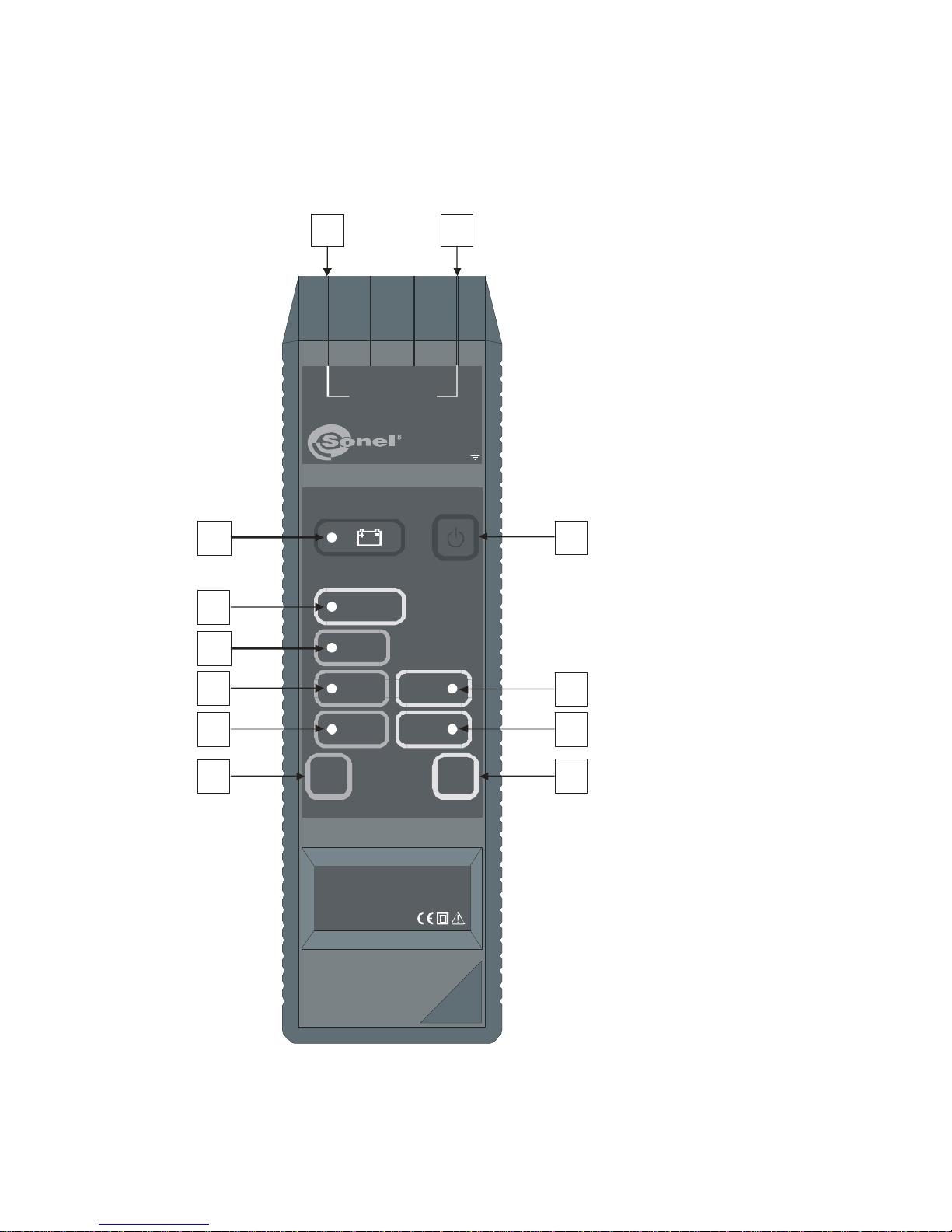
4.1 Transmitter LKN-700
4.1.1 Front Panel
1 2
3
8
9
1
1
1
1
0
2
5
7
4
6
MAX 500V RMS
CAT. III 600V
OUTPUT
POWER
OUTPUT
OK
MODE
AUTO
E
M1
2
LKN-700
Fig.1. Detector’s transmitter (front panel)
Sonel S.A.
10
NOTE!
The transmitter is designed to work with the rated voltage of 230/400V.
Connecting the device to voltage that exceeds 500VAC can damage
the instrument.
1 Jack plug
A socket for connecting the tested installation.
2 Jack plug
A socket for connecting the tested installation.
3 Button
On/Off switch.
4 Button
MODE
Mode switch.
5 Button
OUTPUT
POWER
Output power setting.
6 LED M
Signals that the device entered a current (“M”)mode.
7LED E
Signals that the device entered a voltage (“E”) mode.
LEDs 6 and 7 glowing simultaneously signal that the device is in a mixed
(current-voltage „M+E”) mode.
8 LED AUTO
Signals that the device is in an auto mode.
9LED OUTPUT OK
Signals that the device is working OK.
10 LED 1
Signals that the low output power was selected.
11 LED 2
Signals that the medium output power was selected.
LEDs 10 and 11 glowing simultaneously signal that the high output power
was selected.
12 LED
Battery discharged.
4.1.2 Audible signals
Warning signals:
Short (ca 0.25 sec.) audible signal repeated every 1s
•Detected voltage in the tested installation (in voltage mode „E”)

Sonel S.A. 11
•The transmitter is unable to generate sufficient current in the current „M” or
current-voltage “M+E”mode
Confirmation and other signals:
Short audible signal
•Button press confirmation
•Change of broadcasting mode in the AUTO mode
Long audible signal (ca 0.5s)
•Self test completed after the transmitter was switched on (signalling of ir-
regularities – see section 8.2)
•Button disabled
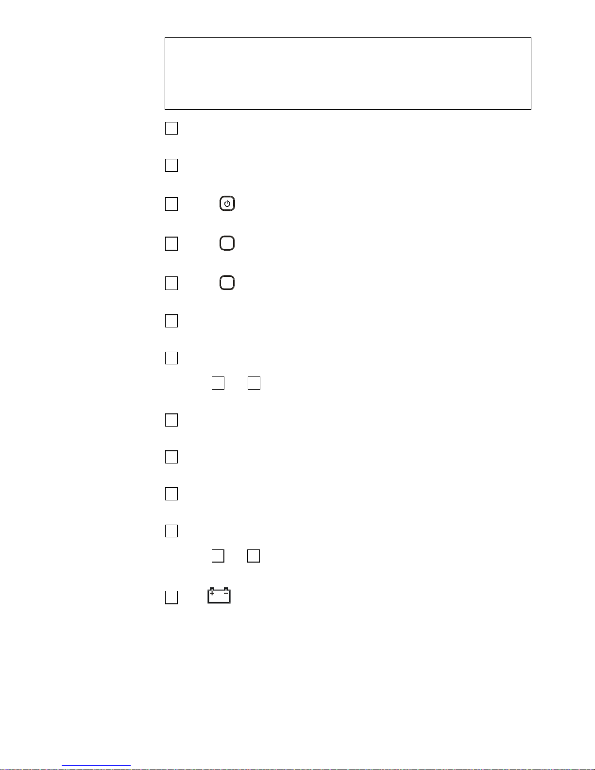
4.2 Receiver LKO-700
4.2.1 Front Panel
17
18
19
22
16
14
21
24
23
15
13
MODE
ZOOM
E M
EM
LKO-700
TRANSMITTER
20
Fig.2. Detector’s receiver (front panel)
Sonel S.A.
12
13 Antenna
Houses device’s magnetic and electric field detectors
14 Button
ON/OFF switch.
15 Button
MODE
Alternating between channels: current or voltage.
16 Button
ZOOM
Turning the precision positioning function on (amplified visualization of
changes in magnetic or electric field).
17 LED gauge
Magnetic/electric field indicator.
18 LED E
Signals that the device is using a voltage channel.
19 LED M
Signals that the device is using a current channel.
20 LED
Signals the neon indicator being activated.
21 LED
Battery discharged.
22 LED TRANSMITTER E
Signals detection of the transmitter’s voltage mode.
23 LED TRANSMITTER M
Signals detection of the transmitter’s current mode.
LEDs 22 and 23 glowing simultaneously signal detection of transmitter’s
mixed (current-voltage „M+E”) mode.
24 LED
Signals detection of an electric field 50/60Hz that originates from phase ca-
bles (neon indicator).
4.2.2 Audible signals
Confirmations and others:
Short audible signal
•Button pressed
•Change in sensitivity sub-range in the ZOOM mode
Long audible signal (ca 0.5s)
•Completion of self test after turning the transmitter on
Modular audible signal
•With frequency directly proporcional to signal level

Sonel S.A. 13
4.3 Leads
Crocodile clips and probes provided with the leads can be placed on cable ter-
minators.
WARNING:
Connecting to the device leads that are inadequately insulated or fea-
ture unsuitable plugs can be dangerous for the operator.
5 Working Principles
5.1 General Information
LKZ-700 system consists of two components: transmitter and receiver.
The transmitter connected to the circuit being traced generates magnetic („M”
mode) or electric („E” mode) field around the circuit.
Magnetic field is created as a result of a suitably modulated current flow-
ing through the tested (closed) circuit.
Electric field is created as a result of a suitably modulated voltage being
applied to the tested (open) circuit (the intensity and the shape of the field de-
pends on the environment in which it is created).
The transmitter placed alongside the tested circuit detects the modulated
field and notifies the user. Mapping of the circuit (cable) route or its defects is
possible through observation of the detected signal intensity level.
5.2 Transmitter
Electromagnetic signals broadcast by the transmitter are appropriately
modulated. Therefore it is possible to differentiate between them and other sig-
nals that may be present in the tested circuit or its immediate vicinity. The signal
has also different signatures for different broadcast modes to enable the re-
ceiver their remote interpretation. Broadcast modes can be switched sequen-
tially from one to another by pressing the 4
MODE
button. Pressing the button ac-
tivates an appropriate LED 6 , 7 , 8 (different work modes are described in
section 6). The 5
OUTPUT
POWER
button can be also used to set (also sequentially) one of
three power levels:
•low – LED 10 1 on
•middle – LED 11 2 on
•high – LEDs 10 1and 11 2 on
Blinking LED 9 OUTPUT OK informs that a test signal is being sent by
the transmitter. LED remaining switched off signals that the broadcast mode
has been incorrectly selected for conditions in the tested circuit.
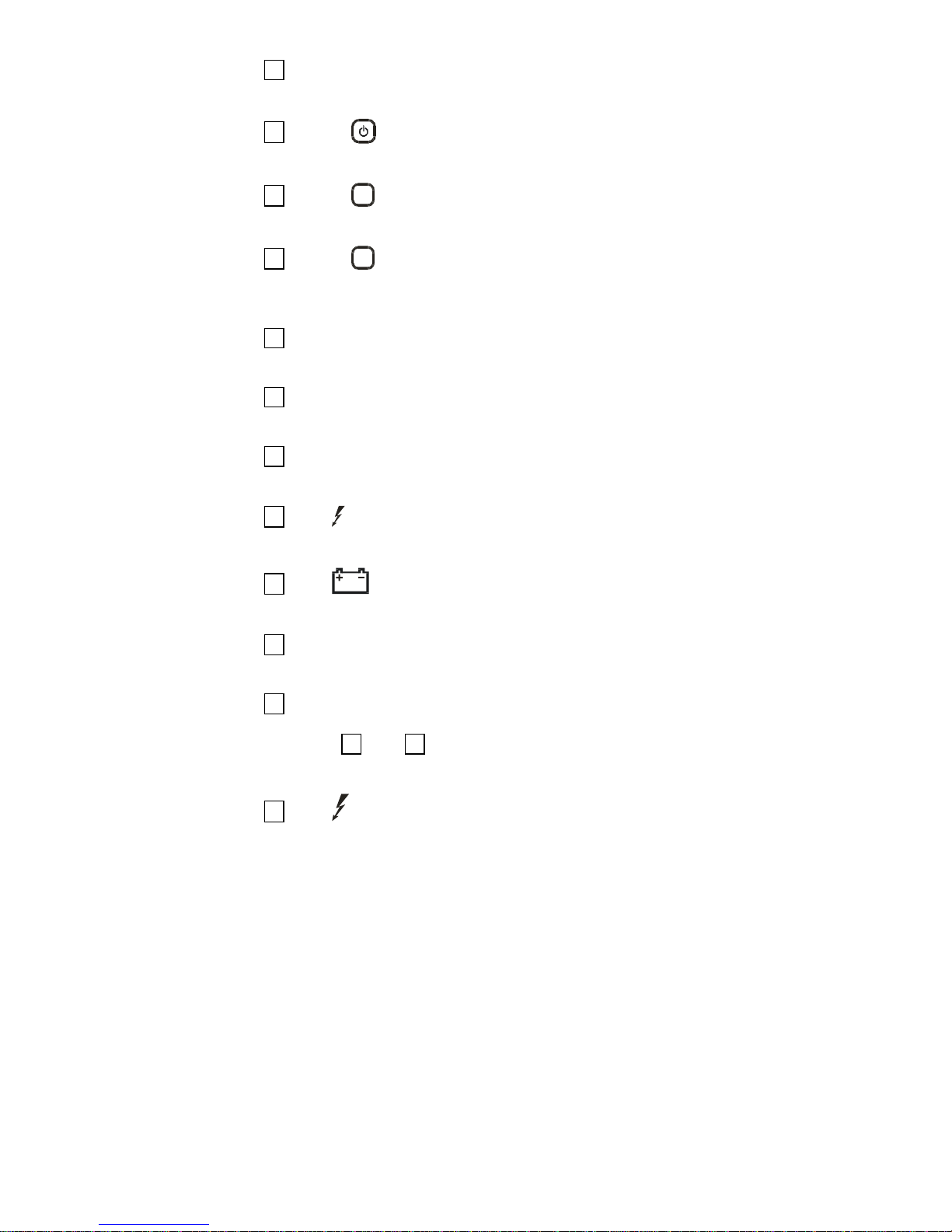
5.3 Receiver
Receiver’s antenna 13 hides two sensors: an electric field detector and a
magnetic field detector. The electric field detector has an aerial shaped in a
form of a metal plate. The magnetic field detector has an aerial shaped as a
coil. The way the aerials are located (Fig. 3) influences directional characteris-
Sonel S.A.
14
tics of the receiver.
An electric field detector’s antenna
Amagnetic fielddetector’s antenna
Fig.3 Location of sensors in receiver’s antenna
Electric or magnetic field strength is indicated by the LED indicator 17
“deflection”. Sensitivity of the receiver is set automatically. To increase instru-
ment’s precision, use the 16
ZOOM
button. Pressing the button causes amplifica-
tion of the LED gauge indications representing changes in the field’s strength
i.e. the range of changes that might be represented by only one or two LEDs
being lit is now illustrated using the entire indication range of the gauge (more
detailed description of this function can be found in section 7.1).
Receiver’s work mode is switched sequentially using the 15
MODE
button
which is accompanied by LED 18 Eor 19 Mor 23 being lit.
Two LEDs 22 TRANSMITTER E and 23 TRANSMITTER M indicate the
currently used transmitter mode.
In the non-contact neon mode the receiver can detect if the tested line is
live and can also locate a live cable. The receiver detects an electric field
50/60Hz displaying its strength on the LED gauge 17 and after exceeding cer-
tain level it turns on the 24 . In this mode the ZOOM function does not work.
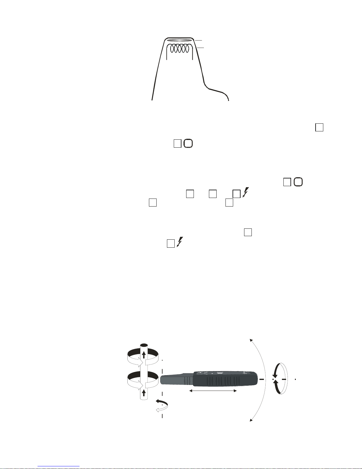
5.4 Closed-Circuit Measurements
Measurements can be performed in a closed circuit provided that a cur-
rent flow can be induced in the circuit. This is the case in a healthy line with
line’s voltage exceeding 9V (the circuit is closed by a transformer) and also in a
shorted line, using the „M+E” mode or and external power source. In all de-
scribed situations the detection is done by evaluating the magnetic component
of the field. Fig.4 illustrates the direction of the magnetic field lines around the
cable in which the modulated current flows, and the placement of the receiver
allowing for the highest possible intensity of the received signal.
A
B
C
MODEZOOMUIUTIT
LK O- 70 0
D
Fig.4 Magnetic field detection
Sonel S.A. 15
Directional properties of the receiver can be observed when we try to
change its position in relation to the cable in directions indicated by the arrows.
Swinging the receiver only in directions “A” does not change the signal level
since the magnetic field detector does not change is position in relation to the
magnetic field lines. On the other hand, rotating the receiver around its axis (ar-
row “C”) will cause gradual signal deterioration until it disappears when rotating
the device by 90º. Similarly, when swinging the receiver in direction “D” (around
the axis of the receiver’s aerial). Also moving the receiver away from the cable
(“B”) will weaken the signal as a result of a decrease in field’s strength with an
increase of the distance.
For a 2-core cable in which the current flows through one of the cores in
one direction and in the opposite direction through the other core, the magnetic
field strength is much lower than in a single-core cable since the fields gener-
ated by the cores cancel each other out. The greater the distance between the
cores, the stronger is the magnetic field. This phenomenon is utilised for detect-
ing all sorts of inconsistencies in power lines e.g. cable boxes, switches, stub
cables, cable ducts constrictions etc.
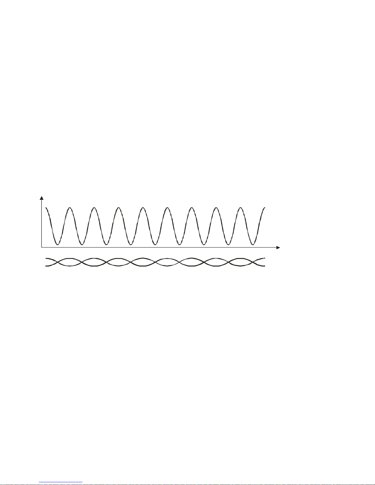
A different field distribution is created around a twisted pair cable. It is not
uniform and changes periodically depending on the relative position of the cores
(Fig. 5). It has to be taken into account when tracking a cable or locating cable
faults.
Twisted pair cable
Magnetic field intensity
Cable length
Fig.5 Magnetic field distribution around a twisted pair cable
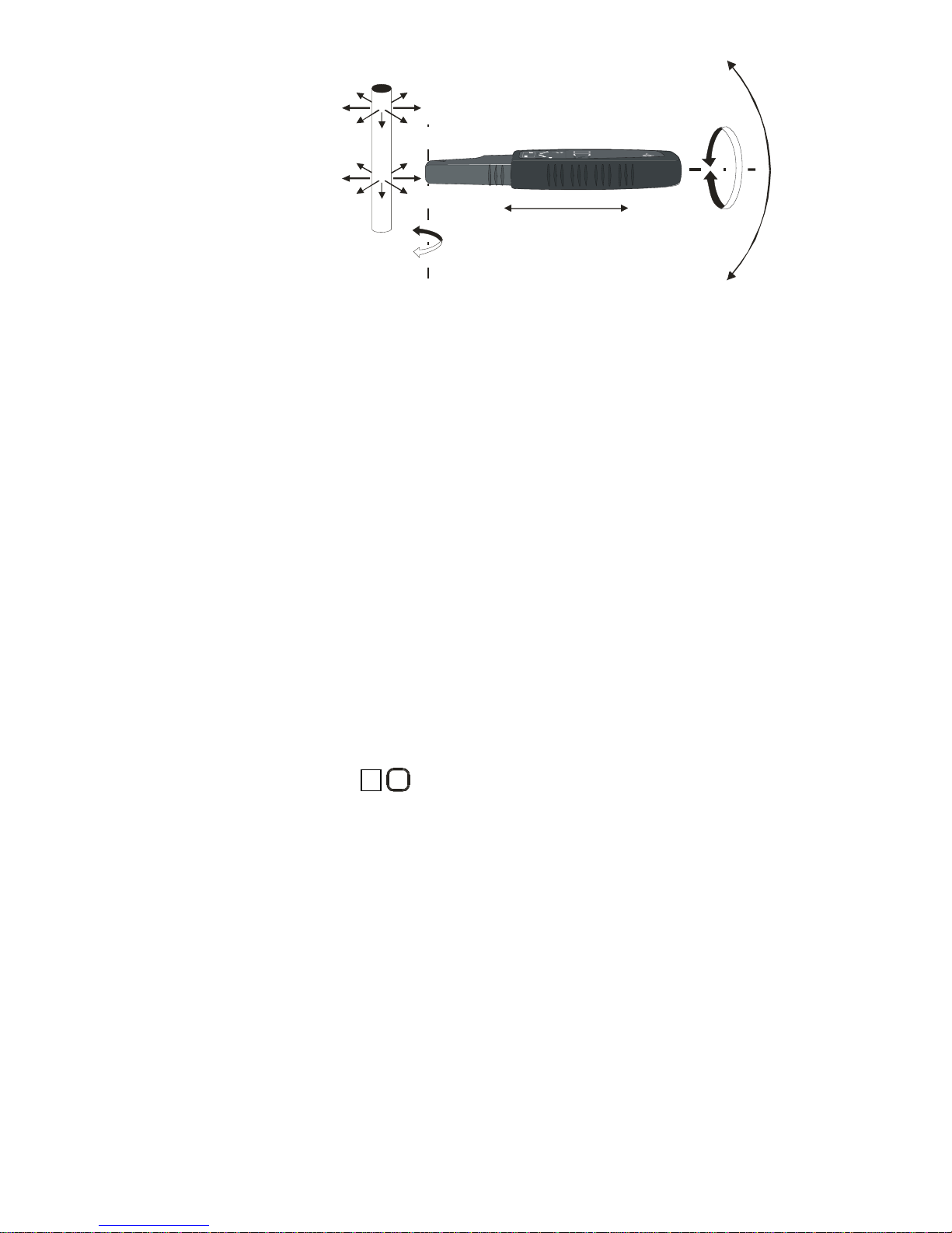
5.5 Open-Circuit Measurements
Measurements in an open-circuit should be carried out if there is no way
to force a current flow through the circuit. This is the case in a healthy long line
that is not live, where using an external power source capable of generating suf-
ficient current would be cumbersome or where the line is interrupted. In both
cases the detection is through evaluation of the electric component of the field.
Fig.6 illustrates the direction of the electric field lines around a live cable, and
the placement of the receiver allowing for the highest possible intensity of the
received signal.
Sonel S.A.
16
A
B
CD
MODEZOOMUIUTIT
LKO- 70 0
Fig.6 Electric field detection
Directional properties of the receiver can be observed when we try to
change its position in relation to the cable in directions indicated by the arrows.
Rotating the receiver around its own axis (“A”) does not change the signal’s
strength since the electric field sensor will not change its position in relation to
the electric field lines. On the other hand, swinging the receiver as indicated by
“B” and “C” (around the axis of the receiver’s aerial) and also in other directions
will cause gradual signal deterioration until it disappears when the field lines
and surface of the receiver are on planes that are parallel to each other. Also
moving the receiver away from the cable (“D”) will weaken the signal as a result
of a decrease in field’s strength with an increase of the distance.
In an open-circuit mode the line powered by the transmitter functions as
an aerial and the earth becomes a reference potential.
6 Work Modes
6.1 General Information
The equipment can work in one of three modes: a current (“M”) mode, a
voltage („E”) mode and a current-voltage („M+E”) mode. In the „AUTO” mode
the receiver automatically selects a mode in accordance with conditions that ex-
ist in the tested line.
Button 15
MODE
of the receiver is used to change the work mode i.e. a volt-
age channel (using the electric field sensor) or a current channel (using the
electric field sensor) is selected or the device is switched into a non-contact
neon mode. In a majority of cases the voltage channel is activated for the trans-
mitter working in a voltage mode and the current channel is activated for the
transmitter working in the current or current-voltage mode. However, in some
circumstances the stronger field is not necessarily the one that would be sug-
gested by the transmitter’s work mode. Therefore a selection can be made.
6.2 “M” Mode
“M” mode is used when working with healthy live cables with the con-
nected voltage not less than 9V.

Sonel S.A. 17
NOTE!
The transmitter is designed to work with the rated voltage of 230/400V.
Connecting the device to a voltage that exceeds 500VAC can damage
the instrument.
One of the transmitter’s output terminals is connected to the phase wire of
the tested cable and the other one to the neutral wire. The voltage that exists in
this circuit is used by the transmitter to generate a current signal (max 40mA) in
a form of high frequency impulses with the amplitude modulated by a lower fre-
quency signal distributed over the time in the way that is specific for the current
mode. The magnetic component of the field generated in this way is then de-
tected by the receiver.
6.3 „E” Mode
“E”mode is used in dead cables where no closed circuit can be estab-
lished (e.g. a break in the cable).
One of the output terminals of the transmitter is connected to the tested
cable and the other to the earth. The transmitter generates a voltage signal in a
form of high frequency impulses with the amplitude modulated by a lower fre-
quency signal distributed over the time in a way that is specific for the voltage
mode. The electric field generated in this way is then detected by the receiver.
6.4 „M+E” Mode
„M+E” mode is used in dead cables where a closed circuit can be estab-
lished (e.g. dead healthy cable, shorted circuit).
One of the output terminals of the transmitter is connected to the phase
wire of the tested circuit and the other one to the neutral wire. Using its own
power supply the transmitter generates a current signal (max 40mA) in a form of
high frequency impulses with the amplitude modulated by a lower frequency
signal distributed over the time in the way that is specific for the current-voltage
mode. The magnetic component of the field generated in this way is then de-
tected by the receiver.
6.5 “AUTO” Mode
In “AUTO” mode the transmitter examines the conditions that exist in the
tested line and selects a mode accordingly:
•If a voltage exceeding 9VAC is detected, a current mode is selected
•If no voltage is detected or the voltage detected is lower than 9VAC and
there is a possibility to force a current flow, a current-voltage mode is se-
lected
•If there is no voltage detected or the voltage is below 9VAC and there is no
way to force a current flow, a voltage mode is selected
Note:
In an “AUTO” mode the AUTO LED and LED(s) corresponding to the
mode selected by the transmitter are on.
Sonel S.A.
18
Note:
If receivers are connected to a tested dead line, then the transmitter in
“AUTO” can select the „M+E” mode. To work in the „E” mode you need
to activate it manually by pressing the 4
MODE
button or to disconnect
all receivers from the tested line.
6.6 „E” (“Power”) Mode
LKZ-700 can also work in a “power” „E” mode. In this configuration the
transmitter in „E” mode is connected to a dead closed circuit. The current
drained from the transmitter is then much higher than in the „M” mode using
maximum power (I
T
>1A for R=0Ωi.e. short circuit). It allows a significant in-
crease of the detection range. In the receiver the „M” mode should be selected
with the voltage signal identified as the transmitted signal (LED 22
TRANSMITTER E on).
This mode is especially recommended for the location of underground
cable routes.
6.7 Audible signallization of field intensity
Receiver has possibility of emitting modular audible signal with frequency
directly proportional to signal level, which additionally is displayed on the rough
scale. To switch off or switch on audible signalization press button 15
MODE
and
16
ZOOM
while keeping power button.
7 Measurements
NOTE!
The transmitter is designed to work with the rated voltage of 230/400V.
Connecting the device to a voltage that exceeds 500VAC can damage
the instrument.
WARNING:
You must not leave one lead disconnected from the device while the
other one is connected to the tested installation.
You must not leave the device connected to tested installation without
supervision.
WARNING:
Always connect the transmitter to the ground first and only than to the
phase wire.
Table of contents
Other Sonel GPS manuals


