Sonetics SON150 User manual


Table of Contents
Overview.................................................................................................................... 1
Contents in Box.......................................................................................................... 2
Accessories (not included)......................................................................................... 2
Features ..................................................................................................................... 3
Wireless DECT7 Communications .......................................................................... 3
Mounting ................................................................................................................... 4
Antennas.................................................................................................................... 5
Duck Antenna......................................................................................................... 5
Accessory Antennas ............................................................................................... 6
Power......................................................................................................................... 7
Option 1: DC Jack Power ........................................................................................ 7
Option 2: Digital Intercom Power .......................................................................... 8
Modular Plug Installation .......................................................................................... 9
LED Indicators .......................................................................................................... 10
Top ....................................................................................................................... 10
Front..................................................................................................................... 10
Use with a Digital Intercom ..................................................................................... 11
Setting up Digital Intercom Mode (default setting) ............................................. 11
Digital Intercom Radio Transmit .......................................................................... 11
Intercom Only ...................................................................................................... 11
Base Station connected to a Sonetics Digital Intercom ....................................... 12
Use with a Legacy Intercom..................................................................................... 13
Setting up Legacy Intercom Mode ....................................................................... 13
Intercom Connections.......................................................................................... 13
Base Station connected to a Sonetics Legacy Intercom....................................... 14
Use in a Comhub...................................................................................................... 15
Setting up Comhub mode, and the number of channels..................................... 15
Pairing...................................................................................................................... 16
Full-Duplex Pairing ............................................................................................... 16
Broadcast Only Pairing ......................................................................................... 16
Example:............................................................................................................... 16
PC Programming ...................................................................................................... 17
Locating the USB Port .......................................................................................... 17
Installation of the Sonetics Configurator Windows Program............................... 17
Troubleshooting....................................................................................................... 18
Service Contact: ................................................................................................... 18
SON150 Specifications............................................................................................. 19
DECT Specifications.............................................................................................. 20
Important Safety Information.................................................................................. 21
Sonetics Standard Limited Warranty....................................................................... 26


1 | Page
Overview
Sonetics Wireless Base Stations support the RF connections of Sonetics wireless
communication systems. The Base Station supports full duplex, conference call
like digital communication for up to five Sonetics DECT7 Wireless Headsets.
Radio PTT capable Headsets can be set up to transmit on a mobile radio via a
Sonetics Digital Intercom. For installations which need a greater number of
users, such as education or tour groups, Broadcast mode supports up to 100
users. Broadcast users share connections to take turns talking with the group.
Sonetics DECT7 wireless, operating on the 1.9GHz band provides secure,
interference-free, full-duplex communication. Wireless Headsets have a
wideband connection of up to 7kHz. This gives a line-of-sight range of up to 1,600
feet. With internal and external antennas, the Wireless Base Station configures
itself for the best reception. Multiple Wireless Base Stations and Intercoms can
be combined to support up to 60 users in a single audio network. USB
programming allows complete customization.

2 | Page
Contents in Box
Base Station
1 ea x Wireless Base Station
Antenna
1 ea x Duck Antenna
1 ea x Duck Antenna Mount
1 ea x Wire Tie
Manual and Reference
1 ea x Manual
1 ea x FCC/IC certification sheet
1 ea x ComCare sheet
Power
1 ea x AC Wall Adaptor
1 ea x DC Power Cable
1 ea x in-line Fuse Holder & Fuse
1 ea x DC Cigarette Lighter Adaptor
Accessories
1 ea x RJ45 Intercom Interface Kit
1 ea x RJ12 Intercom Interface Kit
8 ea x RJ12 Connectors
1 ea x Mounting Feet Kit
1 ea x USB Cable
Accessories (not included)
Magnet Mount Remote Antenna
RJ12 Flat Cable
Permanent Antenna
Auxiliary Input Radio Interface - Connect to virtually any radio
and many other devices
Worldwide Power Adaptor

3 | Page
Features
USB Programmable
Using its USB port, a Base Station can be configured using a Windows PC.
Features may be customized and saved. Refer to the Sonetics Headset Software
for details.
Wireless DECT7 Communications
The Base Station features wireless DECT7, enabling conference call-like full
duplex communication. The Sonetics wireless DECT7 Base Station will connect
with Sonetics Wireless Headsets and Belt Packs. DECT7 networks have up to
1600ft line-of-sight range in Region 1 (US) and up to 800 meters in Region 2 (EU).
DECT7 ensures interference free, digitally encrypted communications for all
parties.
Backwards Compatibility
The Sonetics wireless Base Station is backwards compatible with the Sonetics
first generation wireless DECT and DECT6 bases, with minimal loss in
functionality.
Wide Band Audio
The Wireless DECT7 communications are transmitted in a high definition wide
band audio format. This gives greater clarity of voice, and allows for integration
with voice activated control systems. It can be switched to narrow band audio
when necessary.
Dual Antenna Design
The Base Station has internal and external antennas for diversity switching to
lock onto the best signal. This allows the installer to place the Wireless Base
Station and antenna in different locations for system optimization in custom
installations.
Multi-Channel System
The Wireless Base Station can be configured for multiple channels. These can be
remotely selected by paired Wireless Headsets.
Broadcast Mode
The Headset may be paired into a listen only mode of operation, reducing power
consumption considerably. This also allows many more headsets to be
connected to a Wireless Base Station simultaneously. Pressing the Radio PTT
button allows the headset to momentarily talk on any available slot. A tone will
let the user know when they can talk. After talking, there will be a slight delay
when other users cannot be heard.
4 | Page
Mounting
The Wireless Base Station is designed to mount on a variety of surfaces. The
unit includes internal and external antennas. Consideration must be given to
antenna location optimize performance.
WARNING: Do not locate the Wireless Base Station within 4” of any
metal.
If the Wireless Base Station must be located in a non-optimal location, use an
external accessory remote antenna.
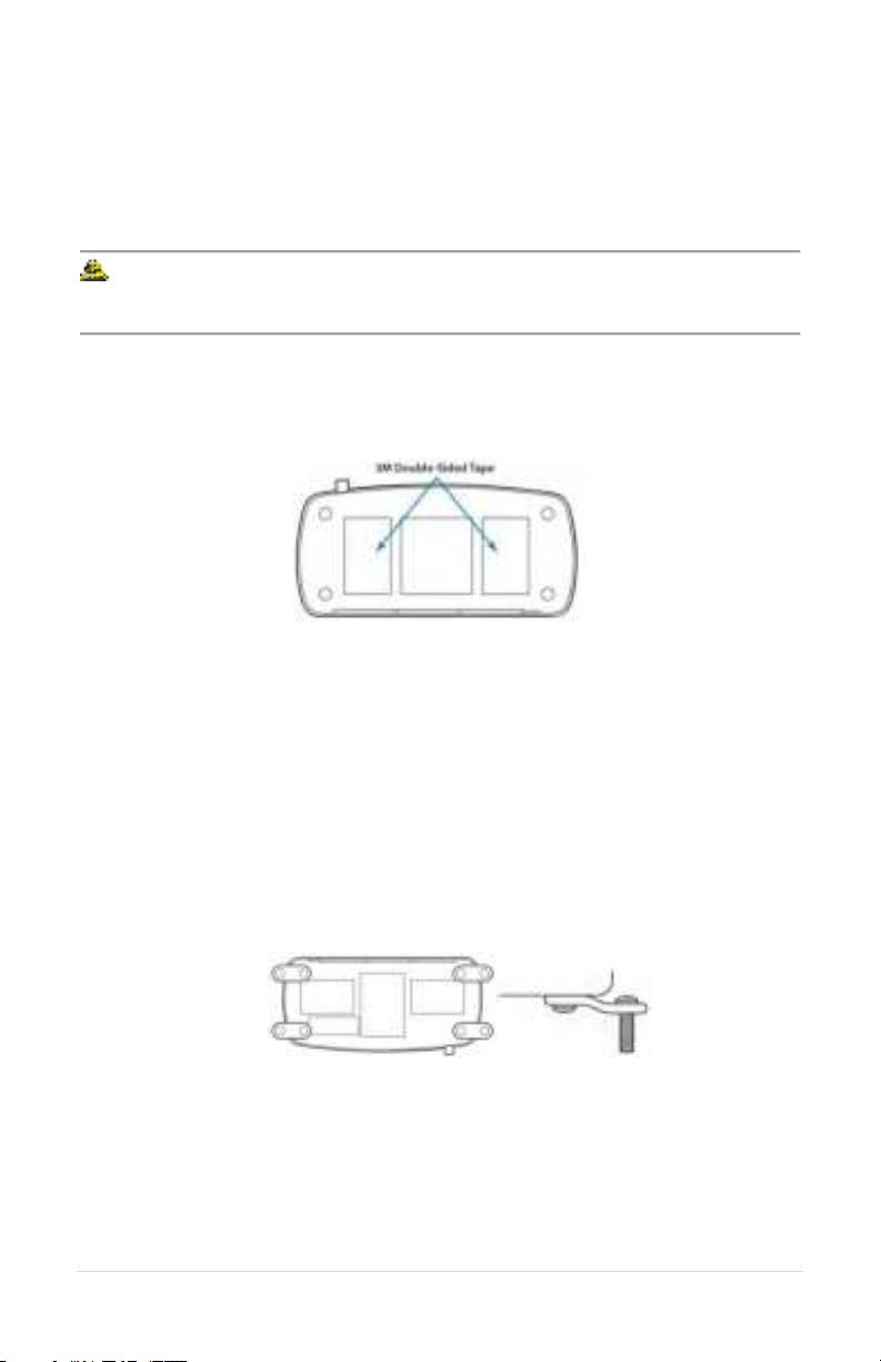
Option 1: Window Glue Mount
1. Remove duck antenna.
2. Clean the location where the wireless base will be installed.
3. Remove the protective backing from the 3M double-sided tape on the
bottom of the wireless base.
4. Press firmly to the window.
Option 2: Fixed mount with Feet
1. Remove one of the screws on the bottom of the Base Station.
2. Place a mounting foot, and attach it using a replacement screw.
3. Repeat for the other three screws.
4. Mount the Wireless Base Station using the mounting feet.
5. Position antenna and use antenna mount to secure it. Alternatively, use a
remote antenna.
Option 3: Desk
1. Place on Desk.
2. Orient the external duck antenna vertically or use a remote antenna.

5 | Page
Antennas
An external antenna can provide a performance increase in some locations, and
affords greater installation flexibility.
To optimize performance:
1. Position the antenna at least 12 inches from any other antenna, metal,
electrical power, radio equipment, or obstructions.
2. Choose a location in the center of the vehicle’s roof (if mounting
outside).
WARNING: For FCC and other Radio Frequency regulatory compliance,
use only Sonetics approved wireless antennas.
Duck Antenna
Always position the Duck antenna at 90 degrees from the internal antenna. The
internal antenna is shown below.
The duck antenna needs to be supported when used in a vehicle or any
environment when the Wireless Base Station may be subjected to vibration.

6 | Page
Accessory Antennas
Sonetics has accessory antennas for temporary and permanent installation on
the exterior of a vehicle or building. To ensure the best system performance,
external antennas must not be mounted inside metal enclosures.
Magnet Mount Antenna
This antenna is designed for non-permanent installations on metallic surfaces.
1. Temporarily mark the center of the vehicle’s roof or trunk. Centering the
antenna on a flat metal area will improve ground plane and increase range.
2. Clean the marked area with rubbing alcohol or other non-corrosive cleaner
to prepare the surface. Let it dry completely.
3. Cut a round piece of felt the same size as the bottom of the magnet mount
and place it on your center mark. Set the magnetic antenna on top of the
felt to protect to the vehicle’s paint from scratches. Use of a felt patch will
slightly reduce the strength of the magnet. Make sure the coaxial cable is
pointed toward where it will enter the vehicle.
4. Open the hood or the trunk. Route the cable through a body panel gap to
get to the base station location.
5. Connect the cable to the antenna connector on your Wireless Base Station.
Do not over tighten the antenna! Finger tight plus 1/8th a turn is sufficient.
Permanent Mount Antenna
This antenna is designed for permanent installation. Have a qualified radio
installer perform the installation.

7 | Page
Power
The Wireless Base Station can be powered from the DC Jack or directly from a
Digital intercom. The unit will automatically power on when power is applied.
WARNING: Use only one power option to prevent ground loops.
Option 1: DC Jack Power
Wall Adapter Charging
Only charge the base station using the supplied 12VDC regulated wall adapter.
WARNING: Use only approved wall adaptors.
Vehicle Charging
Connect the BLACK wire with WHITE dashes to +12V and the BLACK wire to
chassis ground. Install the fuse no further than 18" from the battery.
WARNING: Only replace fuse with the same type, 0.5A AGU.
WARNING: Voltages exceeding the Base Station charging specification
will damage the Base Station.

8 | Page
Option 2: Digital Intercom Power
1. Connect one RJ-45 modular plug as shown above. Both the Power and
Ground will be connected from the Digital Intercom to the Wireless Base
Station. Any input will power the Wireless Base Station.
2. Adjust the fuse of the Digital Intercom to include the current draw from
the Wireless Base Station.
3. Additional connections to the Digital Intercom using a 6 pin wire, and RJ-12
connectors.

9 | Page
Modular Plug Installation
1. Using the cutter blade on the crimping tool (A), cut the flat CA Cable so the
cut is clean and 90 degrees to the sides of the cable.
2. Insert one end of the CA Cable between the stripping blades (C) until the
end of the cable hits the stop (B).
3. Squeeze the handles of the crimping tool together until the tool bottoms
out.
4. While holding the handles together, pull the cable out of the tool.
5. The stripped insulation should expose approximately 3/16” of wire.
6. Push a RJ Modular Plug into the plug holder on the crimping tool (D) until
the release tab on the plug locks into position.
7. Holding the cable so that the printed side (or smooth side) of the cable is
toward the release-tab on the plug, push the cable into the plug as far as it
will go.
ALWAYS make sure the printed side (or smooth side) of
the cable is facing the release-tab on the RJ Modular Plug.
8. Squeeze the tool handles COMPLETELY together. You may feel the crimper
finish punching the contacts through the insulation on the wires.
9. Let the handles spring open.
10. Push down on the release-tab on the RJ Modular Plug and remove the RJ
Modular Plug from the crimping tool.
11. Inspect the plug to ensure that the cable is held securely in place.
10 | Page
LED Indicators
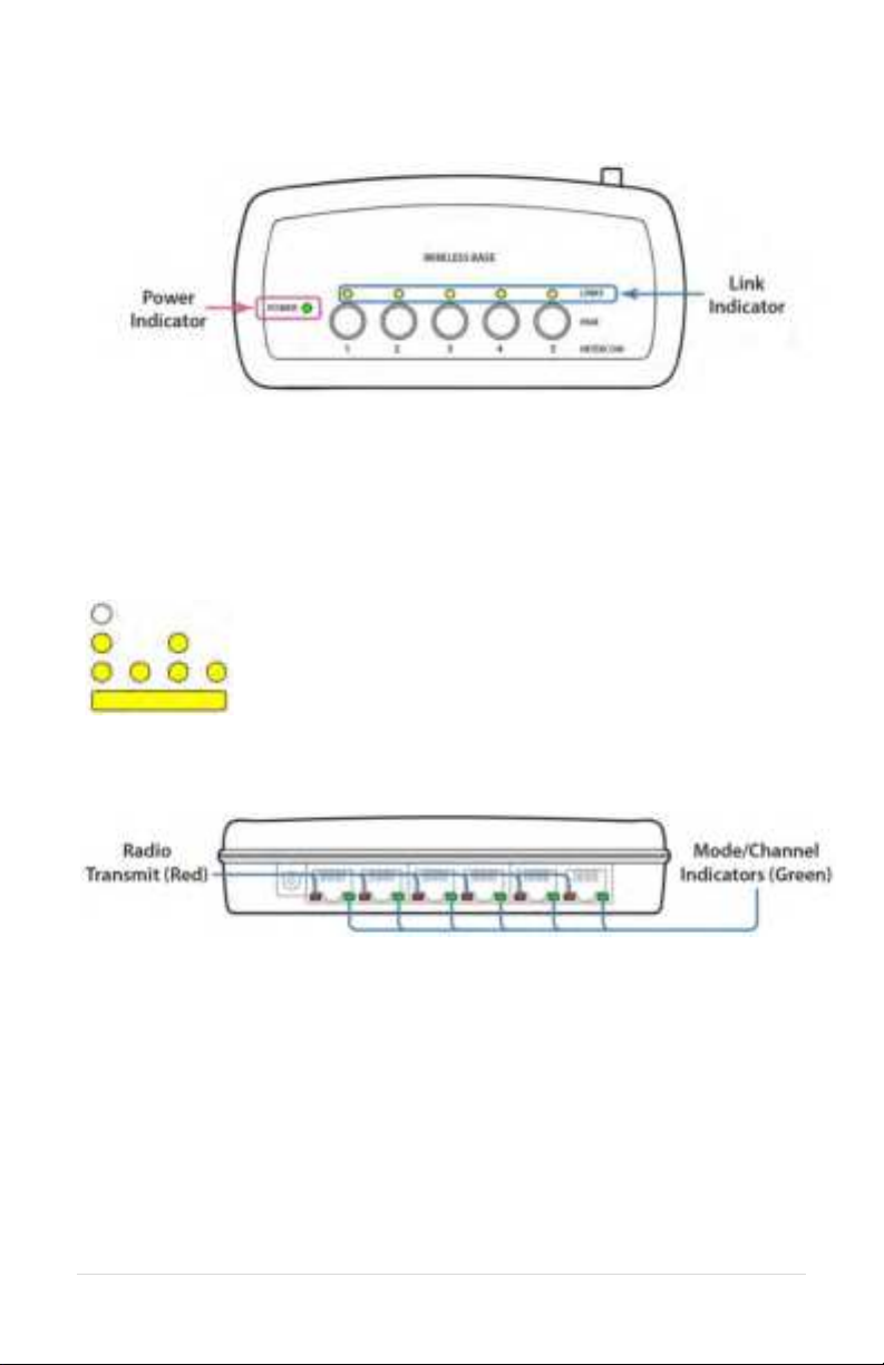
Top
Power Indicator
Lights when unit has power and is turned on.
Link Indicators
There is one light per wireless position. These indicate the connection status of
the wireless devices paired onto the Wireless Base.
Off – No wireless device is paired to this position
Slow Flashing – Pairing Mode Active
Fast Flash – Device paired, no connection.
Solid Light – Device paired and connected
Front
Radio Transmit (Red LEDs)
Indicates the radio transmit activity for each output.
Mode/Channel Indicators (Green LEDs)
These are used to set up the Base Station for Comhub, Intercom, or Legacy
Intercom functionality.

11 | Page
Use with a Digital Intercom
(SON200 Series Digital Intercoms)
The Wireless Base Station is designed to integrate into a Sonetics Intercom
system. This lets the user operate two-way-radios with a Wireless Headset.
When used in Intercom mode, the Base Station must be connected to a Sonetics
Intercom for Headsets to communicate with one another. Only one channel is
available in Digital Intercom Mode.
Setting up Digital Intercom Mode (default setting)
1. Unplug the Base Station, then plug it back in while holding the Pairing
buttons for positions 1 and 2 until the green channel indicator LEDs for
positions 1 and 2 light up (about 5 seconds).
2. The Base Station is now in Digital Intercom mode.
3. Unplug the Base Station, then plug it back in. The Base Station is now ready
to use.
Digital Intercom Radio Transmit
Some models of Wireless Headsets have radio transmit capability built in.
Headsets can receive and transmit via the built in PTT button. The Wireless Base
Station must be connected to a Sonetics intercom that is connected to a two-
way-radio. Consult your Intercom manual for instructions on how to connect
them.
1. Make sure your Headset is a radio transmit model and that it is configured
to transmit radio over DECT. Consult your Headset manual for instructions.
2. Pair the Headset to the desired position on the Base Station.
3. Connect the port for that position to a Sonetics Intercom using a flat cable.
4. Repeat for other positions needing Radio transmit capability.
5. Test and verify each position. The Red LED next to the connected port on
your base station will light when the Headset is radio transmitting.
Intercom Only
For Intercom only functionality, the Wireless Base can be connected to the
Sonetics Intercom using the intercom port. All Headsets will communicate over
the intercom using only position 6. No radio push to talk function will be
available.
1. Pair the Headset to the desired position on the Base Station.
2. If radio transmit capability is needed for a headset, follow the instructions
above under "Digital Intercom Radio Transmit".

12 | Page
Base Station connected to a Sonetics Digital Intercom
Examples:
Stand Alone, No Radio Interface
All positions communicate locally via the Base Station
only. With no connection to a Digital Intercom, the
Headsets will only be able to communicate with other
Headsets connected to the Wireless Base Station.
Intercom Only Connected to Digital Intercom
All positions communicate over the Intercom only. No
radio transmit is available.
Mixed mode, Radio PTT with Intercom only Connected to Digital
Intercom
Positions 1 & 2 have radio transmit capability. All
positions have intercom communications through the
intercom port. Positions 3, 4, and 5 do not have radio
transmit capability (any position connected via its own
cable will have radio transmit capability).

13 | Page
Use with a Legacy Intercom
(30XXR, 110, and 210 Intercoms)
The Wireless Base Station is designed to integrate into older Legacy Sonetics
Intercom systems. This lets the user operate two-way-radios with a Wireless
Headset. When used in Legacy Intercom mode, the Wireless Base Station must
have Ports 1 and 6 connected to the Sonetics Intercom. This allows Intercom
Only Headsets to hear the communications of a Headset utilizing radio transmit.
Only one channel is available in Legacy Intercom Mode.
Setting up Legacy Intercom Mode
1. Unplug the Base Station, then plug it back in while holding the Pairing
buttons for positions 2 and 3 until the green channel indicator LEDs for
positions 2 and 3 light up (about 5 seconds).
2. The Base Station is now in Legacy Intercom mode.
3. Unplug the Base Station, then plug it back in. The Base Station is now ready
to use. In this mode, the position a Headset is paired to does not impact its
operation.
Intercom Connections
1. In this mode port 6 must be connected to a Sonetics Intercom using the
supplied flat cable.
2. Pair the Headset(s) to the Base Station. For Radio Transmit operation, make
sure your Headset is a radio transmit model and that it is configured to
transmit radio over DECT. Consult your Headset manual for instructions.
If Radio Transmit operation is required, connect port 1 to the Sonetics
Intercom using the correct type flat cable. The Sonetics Intercom must be
connected to a two-way-radio.
Operation
All non-radio transmit audio is through Port 6 of the Base Station. When a Radio
Transmit Headset initiates a transmission by activating its PTT button, its audio
is switched to Port 1 along with the PTT signal.

14 | Page
Base Station connected to a Sonetics Legacy Intercom
Examples:
Intercom Only Connected to Digital Intercom
The Intercom port only is connected. All paired
devices will only transmit over the Intercom. No
intercom radio transmit is available. Make sure all
Headsets are set to intercom only modes.
Radio PTT Connected to Digital Intercom
Positions 1 through 5 are radio transmit capable. PTT
signal for all paired devices operate through the
position 1 connection. The Intercom continues to
operate through the Intercom Port.

15 | Page
Use in a Comhub
In addition to being used in an installed system, your Base Station can be used in
a portable Comhub. Up to 5 channels are available through the Wireless Base
Station when used in this configuration.
Setting up Comhub mode, and the number of channels
To enter configuration mode:
1. Unplug the Base Station, then plug it back in while holding the position 3
pairing button.
2. Hold the pairing button until the green channel indicator LED turns on (see
"Mode/Channel Indicators" on page 10).
3. The Base Station is now in Comhub mode.
4. To set the number of available channels, press the pair button
corresponding to the number of channels desired (button 2 = 2 channels,
etc). The current number of channels is shown with a green LED on the
associated Mode/Channel Indicator (e.g. Port 5 = 5 channels).
5. To exit configuration mode, unplug your base station from power, then plug
it back in. The Base Station is now ready to use.
16 | Page
Pairing
Pairing creates a connection between the Wireless Base Station and the Headset.
This is only required once. After pairing, Headsets will connect automatically.
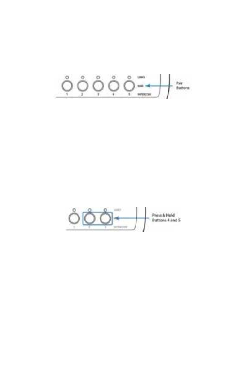
Full-Duplex Pairing
1. Press and hold the desired pairing button until its link indicator begins to
flash slowly. Any previous pairing will be forgotten.
2. Place the Sonetics Headset into pairing mode by pressing the right PTT
button and the power button until you hear "base station registering".
3. The Base Station will automatically connect, showing a solid link led.
4. If the pairing was unsuccessful, repeat all steps above.
Broadcast Only Pairing
Broadcast Only allows up to 100 devices to be paired. One active full duplex
pairing must exist for the Broadcast channel to be opened. Broadcast users never
have Radio Transmit capability.
Example: Position 1 has a Full Duplex Headset pairing. Positions 2-4 are available
for devices to share. Position 5 broadcasts back to the group.
1. Press and hold Buttons 4 & 5 until 4 & 5 link LEDs begin to flash slowly.
2. Place the wireless device you wish to link into pairing mode.
3. The wireless base will automatically connect showing a solid link LED on
position 5 and the device will show connected (refer to the Sonetics device
manual).
4. If the pairing was unsuccessful, repeat steps 1-3.
5. To pair additional devices, repeat steps 1-4.
Because Broadcast Only Headsets share communication positions, there can be
slight delays in communication. To talk, the Push-To-Talk button must be held
until a position opens. After a Broadcast call is made, there will be a pause in
which incoming communications cannot be heard.
To exit Broadcast Only mode:
Press and hold 4 or 5 until the link LED flashes slowly indicating pairing mode.
Other manuals for SON150
1
Table of contents
Other Sonetics Accessories manuals


