Sonetics SON150 User manual


Table of Contents
Overview.................................................................................................................... 1
Contents in Box.......................................................................................................... 2
Accessories (not included)......................................................................................... 2
Features ..................................................................................................................... 3
Wireless DECT Communications ............................................................................ 3
Mounting ................................................................................................................... 4
Option 1: Window Glue Mount.............................................................................. 4
Option 2: Fixed mount with Feet ........................................................................... 4
Option 3: Desk........................................................................................................ 4
Antennas.................................................................................................................... 5
Duck Antenna......................................................................................................... 5
Accessory Antennas ............................................................................................... 6
Power......................................................................................................................... 7
Option 1: DC Jack Power ........................................................................................ 7
Option 2: Digital Intercom Power .......................................................................... 7
Modular Plug Installation .......................................................................................... 8
Connecting to an Intercom ........................................................................................ 9
Radio Transmit ....................................................................................................... 9
Intercom Only ........................................................................................................ 9
Examples: ............................................................................................................. 10
LED Indicators .......................................................................................................... 11
Top Indicators ...................................................................................................... 11
Front Indicators.................................................................................................... 11
Paring....................................................................................................................... 12
Full-Duplex Paring ................................................................................................ 12
Listen Only Paring ................................................................................................ 12
PC Programming ...................................................................................................... 13
Locating the USB Port .......................................................................................... 13
Installation of the Sonetics Configurator Windows Program .............................. 13
Troubleshooting....................................................................................................... 14
Service Contact: ................................................................................................... 14
Specifications........................................................................................................... 16
DECT Specifications .............................................................................................. 17
Important Safety Information.................................................................................. 18
General Communication Privacy Notice .............................................................. 18
Sonetics Standard Limited Warranty....................................................................... 23

1 | Page
Overview
Wireless base stations support the RF connections of Sonetics wireless
communication systems. Housed in a compact rugged case, the Multiple-User
Base Station maintains digital communication with up to five Sonetics wireless
headsets in full duplex(like a conference call) with each able to activate a radio
PTT remotely thru the Sonetics Digital Intercoms. For additional users, the
wireless base has the ability to have up to 100 users in listen only mode for use
in applications like tour groups. The listen only users also have the ability to
take turns to talk with the rest of the group. Sonetics DECT7 operating on the
1.9GHz, the base station provides secure, interference-free, full-duplex
communication, and wide band up to 7kHz with Sonetics wireless headsets up
to a 1,600-foot line-of-sight radius. With an internal and external antenna, the
wireless base configures the user’s application for best wireless results.
Multiple base stations can be combined with one or more intercom units to
support up to 60 users in a single local digital audio network. USB
programmable enables the site administrator extended control like adding
channels and specific connection profiles.
2 | Page
Contents in Box
Base Station
1 ea x Wireless Base Station
Antenna
1 ea x Duck Antenna
1 ea x Duck Antenna Mount
Manual and Reference
1 ea x Quick Reference Guide
1 ea x Manual
Power
1 ea x AC Wall Adaptor
1 ea x DC Power Cable
1 ea x in-line Fuse Holder & Fuse
Accessories
1 ea x Intercom Interface Kit
4 ea x Mounting Feet
1 ea x USB Cable
Accessories (not included)
Magnet Mount Remote Antenna
Permanent Antenna
Auxiliary Input Radio Interface - Connect to virtually any radio
and many other devices
Worldwide Power Adaptor

3 | Page
Features
USB Programmable
The wireless base has a built in USB port for configuring with your Windows PC.
Each feature and setting may be customized to your individual application.
Wireless DECT Communications
The headset features a wireless DECT communication channel enabling full
duplex communication, like a phone call, to others on the same channel. The
Sonetics wireless DECT base station will connect with Sonetics wireless
headsets and belt packs. This DECT communication network gives the user up
to 1600ft line-of-sight to the wireless base in Region 1 (US) and up to 800
meters in Region 2 (EU). The standard further ensures interference free and
digitally encrypted communications amongst all parties.
Backwards Compatibility
The wireless headset is backwards compatible with the Sonetics first
generation wireless bases with minimal loss in functionality.
Wide Band Audio
The wireless DECT communications are transmitted in a high definition wide
band audio format. This allows greater intelligibility of the user and integration
with voice activated control systems. This feature is defeatable to allow the
user to be in a narrow band audio communication.
Dual Antenna Design
There is an internal antenna and an external antenna for diversity switching to
lock onto the best signal. This allows the installer to place the wireless base in
optimal location while being able to remotely locate the antenna if needed.
Two-Channel System
The wireless base has 2 channels able to be remotely selected by the wireless
headsets.
Listen Only Mode
The headset may be paired into a listen only mode of operation reducing the
power consumption considerably. Up to 100 wireless headsets may be paired
and active in listen only mode. A headset may transition to talk mode
momentarily in a first in first out basis.

4 | Page
Mounting
The wireless base is designed to mount on a variety of surfaces. The unit
includes an internal antenna and an external antenna. Consideration must be
made to optimize the antenna performance.
WARNING: Do not locate the wireless base within 4” of any metal.
If the wireless base must be located in a non-optimal location, use an external
accessory remote antenna.
Option 1: Window Glue Mount
1. Remove duck antenna.
2. Clean the location where the wireless base will be installed.
3. Remove the protective backing from the 3M double-sided tape on the
bottom of the wireless base.
4. Press firmly to the window.
Option 2: Fixed mount with Feet
1. One at a time, remove the wireless base screw.
2. Replace with the supplied foot and replacement screw.
3. Repeat for all 4 wireless base screws.
4. Affix the wireless base to the location using the feet.
5. Position antenna and use antenna mount to affix into place or use
external remote antenna.
Option 3: Desk
1. Place on Desk.
2. Orient the external duck antenna vertically or use a remote antenna.
WARNING: Only use approved external antennas.

5 | Page
Antennas
The external antenna provides performance increase and flexibility in
installation.
To optimize performance:
1. Position the antenna at least 12 inches from any other antenna, metal,
electrical power, radio equipment, or obstructions.
2. Choose a location in the center of the vehicle’s roof (if mounting
outside).
WARNING: For FCC and other Radio Frequency regulatory compliance,
use only Sonetics approved wireless antennas.
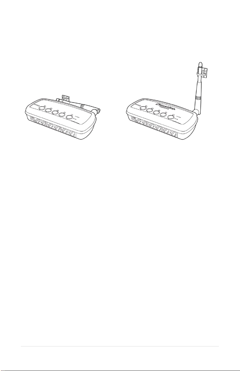
Duck Antenna
Always position the Duck antenna at 90 degrees from the internal antenna. The
internal antenna is shown below.
6 | Page
The duck antenna needs to be supported when used in a vehicle or any
environment when the wireless base may be subjected to vibration.
Accessory Antennas
Sonetics has accessory antennas for temporary and permanent installation on
the exterior of a vehicle or building.
Magnet Mount Antenna
This antenna is designed for non-permanent installations on metallic surfaces.
1. For optimal results, find the center of the vehicle’s roof or trunk where you
will locate the antenna. Temporarily mark this location. This will provide
you with ground plane by giving equal distance around the sides of the
antenna.
2. Clean the marked area with rubbing alcohol or other non-corrosive cleaner
to prepare the surface for the mount. Let it dry for a few minutes.
3. Cut a round piece from a felt sheet the same size as the magnet mount
bottom. Put the felt on the center of the ground plane and place the mag
antenna on top of the felt. This is to protect to the vehicle’s paint from
scratches. While placing the antenna, make sure the coaxial cable is facing
the vehicle's front.
4. Open the hood or the trunk. Run the cable through the crevice that is
closest to the rear window. Route this cable to the base station’s location.
5. Insert the cable into the base station’s antenna port.
Permanent Mount Antenna
This antenna is designed for permanent installation. Have a qualified radio
installer perform the installation.

7 | Page
Power
The wireless base station can be powered from the DC Jack or directly from a
Digital intercom. The unit will automatically power on when power is applied.
WARNING: Use only one option to power the wireless base to prevent
ground loops.
Option 1: DC Jack Power
Wall Adapter Charging
Only charge the headset using the supplied 12VDC regulated wall adapter.
WARNING: Use only approved wall adaptors.
Vehicle Charging
Connect the RED wire to +12V and the BLACK wire to battery chassis ground.
Install the fuse no further than 18" from the battery.
WARNING: Only replace fuse with the same type, 1.5A AGU.
WARNING: Voltages exceeding the headset charging specification will
damage the headset.
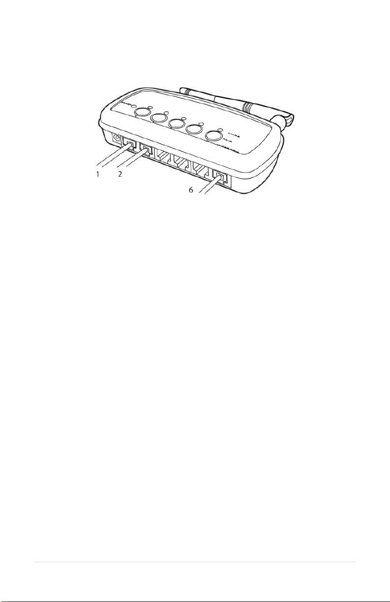
Option 2: Digital Intercom Power
1. Connect one RJ-45 modular plug as shown above. Both the Power and
Ground will be connected from the Digital Intercom to the Wireless Base. Any
input will power the wireless base.
2. Adjust the fuse of the Digital intercom to include the current draw from the
wireless base.
3. Additional connections to the digital intercom need only the middle
connections using a 6 pin RJ-12 connector.
8 | Page
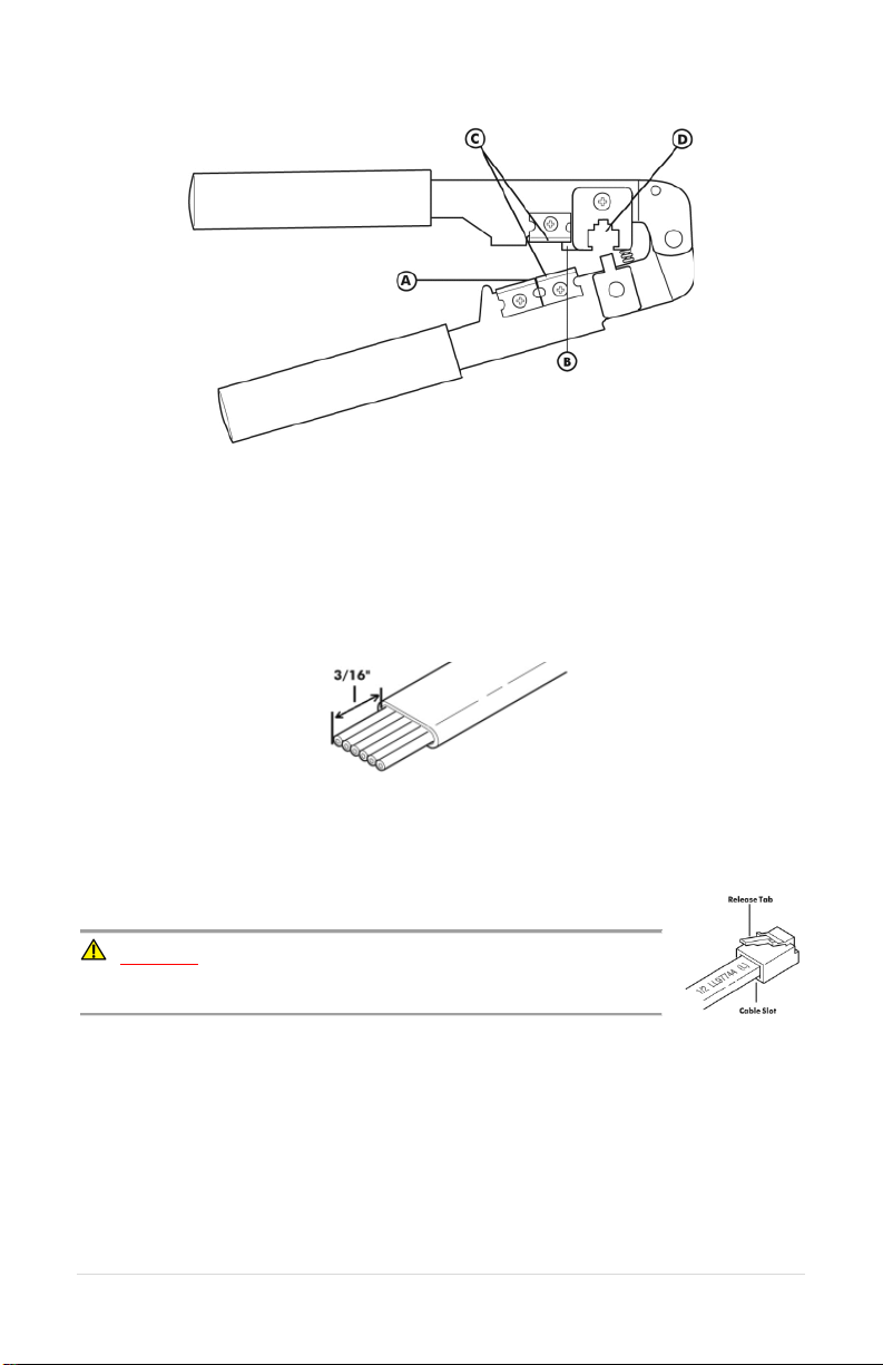
Modular Plug Installation
1. Using the cutter blade on the crimping tool (A), cut the flat CA Cable so the
cut is clean and 90 degrees to the sides of the cable.
2. Insert one end of the CA Cable between the stripping blades (C) until the
end of the cable hits the stop (B).
3. Squeeze the handles of the crimping tool together until the tool bottoms
out.
4. While holding the handles together, pull the cable out of the tool.
5. The stripped insulation should expose approximately 3/16” of wire.
6. Push a RJ Modular Plug into the plug holder on the crimping tool (D) until
the release tab on the plug locks into position.
7. Holding the cable so that the printed side (or smooth side) of the cable is
toward the release-tab on the plug, push the cable into the plug as far as it
will go.
ALWAYS make sure the printed side (or smooth side) of
the cable is facing the release-tab on the RJ Modular Plug.
8. Squeeze the tool handles COMPLETELY together. You may feel the crimper
finish punching the contacts through the insulation on the wires.
9. Let the handles spring open.
10. Push down on the release-tab on the RJ Modular Plug and remove the RJ
Modular Plug from the crimping tool.
11. Inspect the plug to ensure that the cable is held securely in place.

9 | Page
Connecting to an Intercom
The wireless base is designed to integrate into a Sonetics intercom system. This
flexibility gives the user the ability to connect two-way-radios to the intercom
and have full use from a wireless headset.
Any position connected to the intercom, except 6, will have radio transmit
capability.
Any position using the intercom connection, position 6, will hear and be heard,
but will not have radio transmit capability.
Any position not connected to the intercom will not be able to hear or be heard
on the intercom.
Radio Transmit
This enables the wireless headset to have radio transmit capability wirelessly at
the headset. The headset will hear everything received from the radio and will
be able to radio transmit over the radio via the PTT button on the headset. The
wireless base must be connected to a Sonetics intercom with the intercom
connected to a two-way-radio for proper operation. Consult your intercom
manual for instruction on how to connect to a radio.
1. Ensure you have a radio transmit wireless headset model or configure the
wireless headset for radio transmit over DECT. Consult your wireless
headset manual for instructions.
2. Pair the radio transmit wireless headset to position 1.
3. Connect the wireless base position 1 port to the Sonetics intercom using
the supplied flat cable.
4. Repeat for other positions needing Radio transmit capability.
5. Test and verify each position.
a. The Red LED adjacent to the base station position will light up
when the headset is in Radio Transmit mode.
Intercom Only
The wireless base can conserve cable connection with the Sonetics intercom
from the intercom only port. All wireless devices will transmit over the
intercom only position 6. No radio PTT signals will be sent over the position 6
location.
1. Pair the wireless headset to position 1.
2. Connect the wireless base position 1 port to the Sonetics intercom.
3. Repeat for other positions needing Radio transmit capability.
10 | Page
Examples:
Mixed mode, Radio PTT with Intercom only
The positions 1 & 2 are configured for radio transmit to the intercom. Pair the
radio transmit headsets to positions 1 & 2. Wireless headsets on positions 1 & 2
will radio transmit out positions 1 & 2 respectively.
Position 6, labeled as intercom, is also connected to the intercom. Headsets
connected to positions 3, 4, and 5 are intercom only and do not have the ability
to radio transmit under any circumstance.

11 | Page
LED Indicators
Top Indicators
Power Indicator
On when unit has power and is on.
Link Indicators
One per wireless position. These indicate the connection status of the wireless
devices paired onto the wireless base.
Off – No wireless device is paired to this position
Slow Flashing – Pairing Mode Active
Fast Flash – Device paired, no connection.
Solid Light – Device paired and connected
Front Indicators
Radio Transmit
Indicates the radio transmit active per output.

12 | Page
Paring
Paring creates a semi-permanent connection between the wireless base and
the device paired. This procedure is only required once to create the link. Each
time the devices turn on, they will automatically remember the last link and
make connection.
Full-Duplex Paring
1. Press and hold one of the paring buttons till the link indicators begins
to flash slowly. Any other device that was previously paired into the
link location will be forgotten.
2. Place the wireless device you wish to link into pairing mode.
3. The wireless base will automatically connect showing a solid link led.
4. If the pairing was unsuccessful. Repeat.
Listen Only Paring
Listen only allows up to 100 devices to be paired and linked to the wireless
base station. Positions 3, 4, and 5 are reserved for listen only when a device is
paired as a listen only device. One device at a time may transition from listen
only to talk. Positions 1 and 2 are reserved for non-listen only paired devices.
Radio transmit is not available on Listen Only Paired devices.
1. Press and hold Buttons 3, 4 & 5 till 3-5 link leds begin to flash slowly.
2. Place the wireless device you wish to link into pairing mode.
3. The wireless base will automatically connect showing a solid link led
on position 5.
4. If the pairing was unsuccessful. Repeat.
5. To pair additional devices, Repeat 1-4.
To exit listen only mode:
Press and hold 3, 4, OR 5 till the link led flashes slowly indicating paring mode.
13 | Page
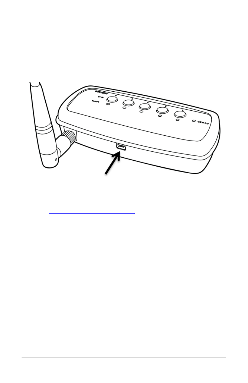
PC Programming
All of the headsets feature a USB port located inside the left dome. Using the
Sonetics Configurator program, you can adjust some additional features on a
Windows PC. Refer to the program for additional information.
Locating the USB Port
Installation of the Sonetics Configurator Windows
Program
1. Go to www.SoneticsCorp.com/software.
2. Download and Install the program for the wireless base station.
3. Plug in the USB cable from the wireless base to the computer.
4. Open the program.
5. Follow the directions of the configurator program.

14 | Page
Troubleshooting
Note: If the symptoms you are experiencing are not covered in this manual, or
if you are having difficulty troubleshooting your system, call us or visit our
website. We’re here to help.
Service Contact:
Phone: 503-684-6647, Service@soneticscorp.com
No indication of power to the base station
•Check wiring to the base station.
No audio communication and/or PTT from or to the base.
•Ensure that power is turned on to the wireless headset(s) and that the
headset(s) are connected.
•Ensure that the modular communication cable is connected between the
base station and intercom.
•Check the modular communication cable between the base station and
intercom for continuity.
•Ensure correct polarity of the modular plug on both ends of the modular
cable.
Poor quality audio, low or distorted received or transmitted audio.
•Ensure that the volume level is properly adjusted on the intercom. For
digital intercom series intercoms, it is recommended that the volume level
is set as high as possible on the intercom without causing distorted audio
on the headset side, and that the volume control on the headset is
adjusted for comfortable listening.
•Poor quality audio can also be caused by a defective headset. Check
operation with a known, well-functioning headset.
•Ensure that the proper base station model for your intercom is used.
Audible interference from portable and mobile radios.
•The wireless system is tested and proven to be immune to interferences
from portable and mobile communication equipment operated anywhere
in the frequency spectrum from 30MHz to 18GHz. However, care should be
taken with installation of communication cables between the intercom and
the base station. These cables should be routed away from portable and
mobile radios and antenna cabling in order to prevent RF interference
from such devices.

15 | Page
Poor coverage range.
•Check location of the base station and external antenna location. The base
station should not be installed inside metal enclosures or any other
location closer than 4 inches to a metal object or surface.
•Poor range can also be caused by a defective headset. Check operation
with a known, well-functioning headset.
If a problem persists contact Sonetics Service for additional help.

16 | Page
Specifications
Physical
Length: 5.70in / 145mm
Width: 2.72in / 69mm (not including external antenna)
Height: 1.22in / 31mm
Weight: 4.8oz / 136g
Power
Voltage Input: 5 VDC to 16 VDC
Maximum Current Input: 400mA @ 5V, 150mA @ 12V
Environmental
IP-Rating: IP-20
Operating temperature:-40°F to 140°F / -40°C to 60°C
Storage temperature:-40°F to 140°F / -40°C to 60°C
FCC
FCC ID: V9N950325700V1
FCC Part 15: All Models
Industry Canada
IC UPN: 7895A-950325700
MIL SPEC
Humidity:MIL-STD 810F and 810G
Temperature Shock:MIL-STD 810F and 810G
SAE
Vibration:J1455 Sec. 4.9
Conducted Immunity:J1113-11
Electrostatic Discharge:J1113-13
Radiated Emissions:J1113-41
Radiated Immunity:J1113-21
ISO
Conducted Transients:7637-2

17 | Page
DECT Specifications
Common DECT Specifications
Carrier Spacing: 1.724 MHz
Time Slots: 2 x 12 (up and down stream)
Channel Allocation:Dynamic
Encryption:DECT Standard Cipher with 35-bit initialization vector
Audio Bandwidth: 300 Hz to 3.4 kHz, Narrow Band, G.726 compression
50 Hz to 7 kHz, Wide Band, G.722 compression
Region 1 Specific Specifications
Authorized for use in: Canada, USA
Frequency Bandwidth: 1920 MHz to 1930 MHz
Number of Carriers: 5
Total Time Slots: 60 in G.726(narrow band) / 30 in G.722(wide band)
Average Output Power: 4 mW
Maximum Output Power: 100 mW
Range (line of sight): 1600 feet maximum
Other manuals for SON150
1
Table of contents
Other Sonetics Accessories manuals

Popular Accessories manuals by other brands


Ericsson
Ericsson MASTR II DESCRIPTION AND MAINTENANCE INSTRUCTIONS

Schmidt
Schmidt SS 20.515 LED Instructions for use

EdgeStar
EdgeStar BWC91SS owner's manual

Ledvance
Ledvance LMS MS-SV-INF-CS-F-360-230V-IP20 installation instructions

WIKA
WIKA PEW-1000 operating instructions

Honeywell
Honeywell Fire-Lite Alarms AD365A Installation and maintenance instructions