TEA TMM-100 User manual

TMM-100
Temperature Measurement Module
Operating Manual
Thermal Engineering Associates, Inc.
3287 Kifer Road
Santa Clara, CA 95051 USA
Revision 4

TEA
TMM-100_User_Manual_r4.doc Rev3 i
CONTENTS
1. Introduction
2. Operation
3. Applications
4. Installation
5. Accessory Items
6. Terminal Command Codes
7. Warranty & Repair
8. Addendum: LabView™ Drivers & VIs
TEA acknowledges the contributions to the TMM-100 design and software made by:
John Keenan, MicroReady Inc.
James Christofferson, Electro-Thermo-Optic
This manual is intended solely for TEA customers in the application of the Temperature
Measurement Module product described herein. The product is designed for the specific
tasks detailed herein and any use of this product in other application tasks is at the user's risk
and responsibility.
©2019 by Thermal Engineering Associates, Inc. (TEA), Santa Clara, CA USA. All rights re-
served. No part of this manual may be copied or otherwise reproduced without prior written
authorization from TEA.
Thermal Test Chips mentioned in this manual are offered for use in characterizing assembly
processes, packages, materials and any other applications requiring precise control of heat
flux generation and temperature measurement. Applying the data from the test die to a func-
tional system is the responsibility of the user. TEA makes no warranty, expressed or implied
including the implied warranties of merchantability and fitness for a particular purpose, that
the user's system designed using that data will perform as intended by the user.
TMM-100 INTRODUCTION
TEA
TMM-100_User_Manual_r4.doc Rev4 1-1
DESCRIPTION
The TMM-100 is designed to simplify the
gathering of temperature data from eight
Thermal Test Chip diode temperature sen-
sors. The system contains precision current
sources for supplying diode measurement
current (IM), voltmeter capability for diode
measurement (VM), and Type-T thermocouple and 10KΩ NTC thermistor measurement ca-
pability for monitoring the environment temperature. Front-panel mounted connectors pro-
vides for up to eight temperature sensing diodes, two thermocouples and two thermistors. All
temperature sensor channels can individually be enabled or disabled using simple com-
mands.
For any of the selected eight diode temperature sensing channels, the internal precision IM
current source provides 1.00mA with a voltage compliance of 2V. The internal voltage meas-
urement circuit measures to 1.999V with 1mV resolution. The temperature measurement
resolution of 0.1C for all sensors provides for accurate temperature differential measure-
ments.
The TMM is powered through its USB connection to a computer, so no external power supply
is required.
FEATURES
Self-contained for easy setup and operation
8 diode voltage measurement channel circuitry
Diode channels use 1.0mA current source.
2 Integrated Type-T thermocouple measurement circuitry
2 10KOhm NTC thermistors measurement circuitry
Thermistor channels use 100µA current source
1mV resolution on differential voltage measurements
Rear Panel connector for controlling temperature environment fan
USB connection for power, programming, and data logging.
LabVIEW Virtual Instrument Option (model TMM-100-01)

TMM-100 INTRODUCTION
TEA
TMM-100_User_Manual_r4.doc Rev4 1-2
SPECIFICATIONS
Diode Current Source
Number of Channels 8
Measurement Current 1.00mA
Accuracy 0.1%
Voltage compliance 1.999V
Polarity - or + to GND
Connection Front Panel, IDC Ribbon Cable Connector
Diode Voltage Measure
Number of Channels 8 (integrated with Current Source)
Range 1.999V
Resolution 1mV
Accuracy 0.01% of fs 1 mV
Temperature Measure (Thermocouple)
Number of Channels 2
Type T
Range 0 to +199C
Resolution 0.1C
Accuracy 0.1% of fs 1.4C
Connector Front Panel, Miniature Jack (Omega NMP-T or equivalent)
Temperature Measure (Thermistor)
Number of Channels 2
Type 10KΩ (nominal @ 25ºC)
Operating Current 100µA
Range 0 to +199C
Resolution 0.01C
Accuracy 0.1% of fs 1.4C
Connector Front Panel, (type TBD)
Power Indicator
Type LED
Color Green
Data Indicator
Type LED
Tx Color Green
Rx Color Red
Computer Connection
Type USB 2.0 or higher
Connector Rear Panel, USB Type B
Relay Connection
Configuration Type Single Pole, Double Throw (SPDT)
Connector Rear Panel
TMM-100 INTRODUCTION
TEA
TMM-100_User_Manual_r4.doc Rev4 1-3
SPECIFICATIONS (continued)
Physical
Height 51.0mm (2.00in)
Length 179.50mm (7.067in)
Width 154.00mm (6.063in)
Weight 0.42Kg (14.7oz)
GETTING STARTED
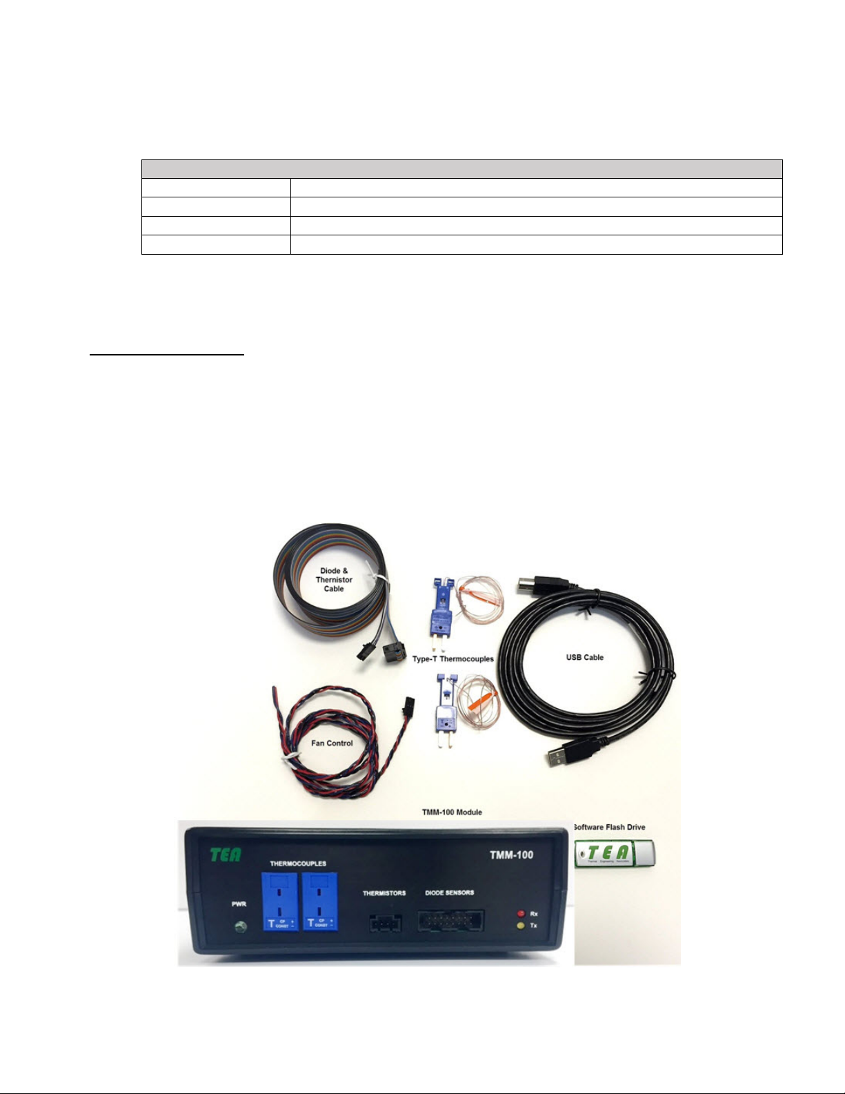
Unpack Your Module
Your box should contain the following items:
TMM-100 Temperature Measurement Module
USB 2.x Cable (Type A on one end, Type B on other end)
Combination Diode/Thermistor Sensors connection cable
Type-T #36 Gauge Thermocouples with mating connectors
USB Flash Drive containing operating software and module operating manual
TMM-100 INTRODUCTION
TEA
TMM-100_User_Manual_r4.doc Rev4 1-4
Hardware Description
Before you cable your router, take a moment to become familiar with the label and the front
and back panels. Pay particular attention to the LEDs on the front panel.
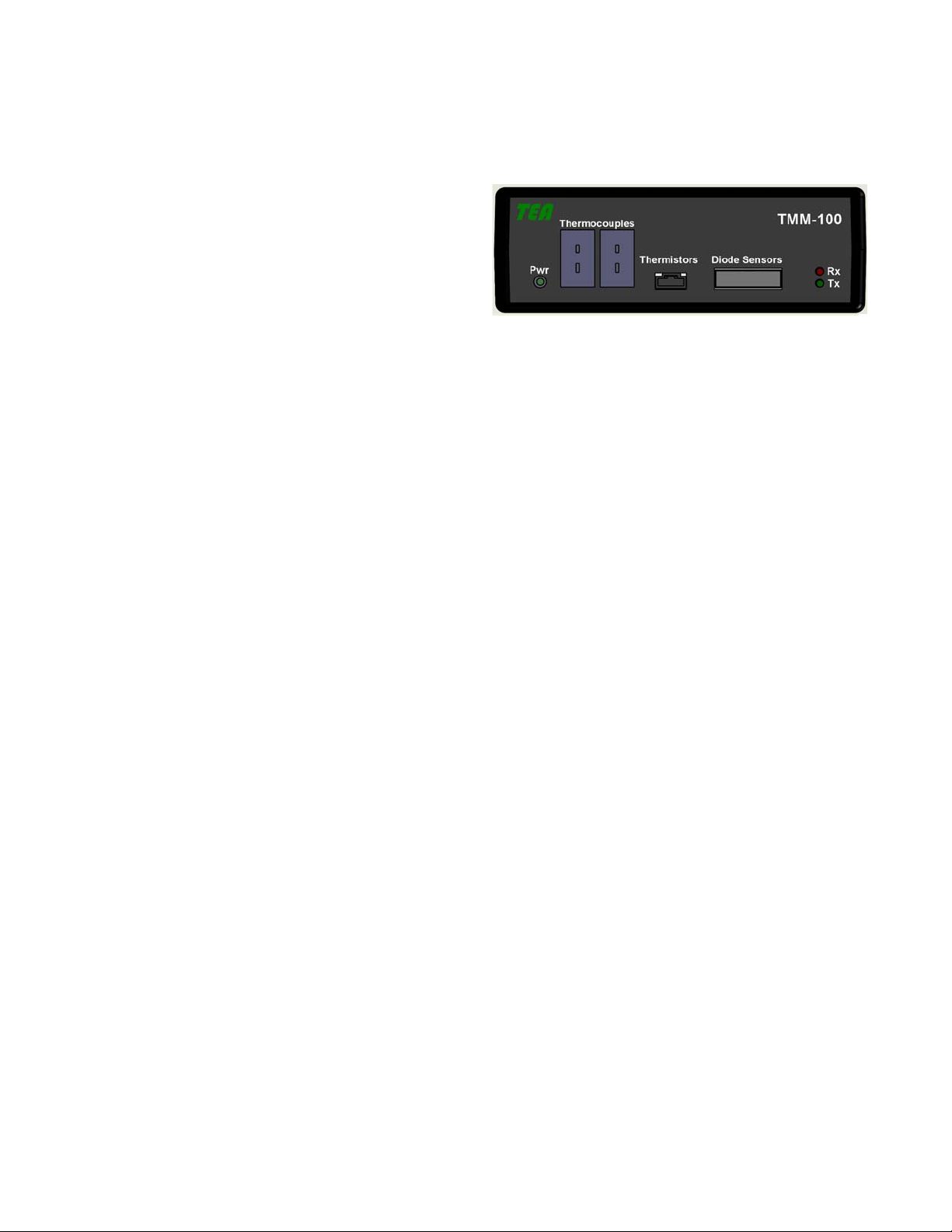
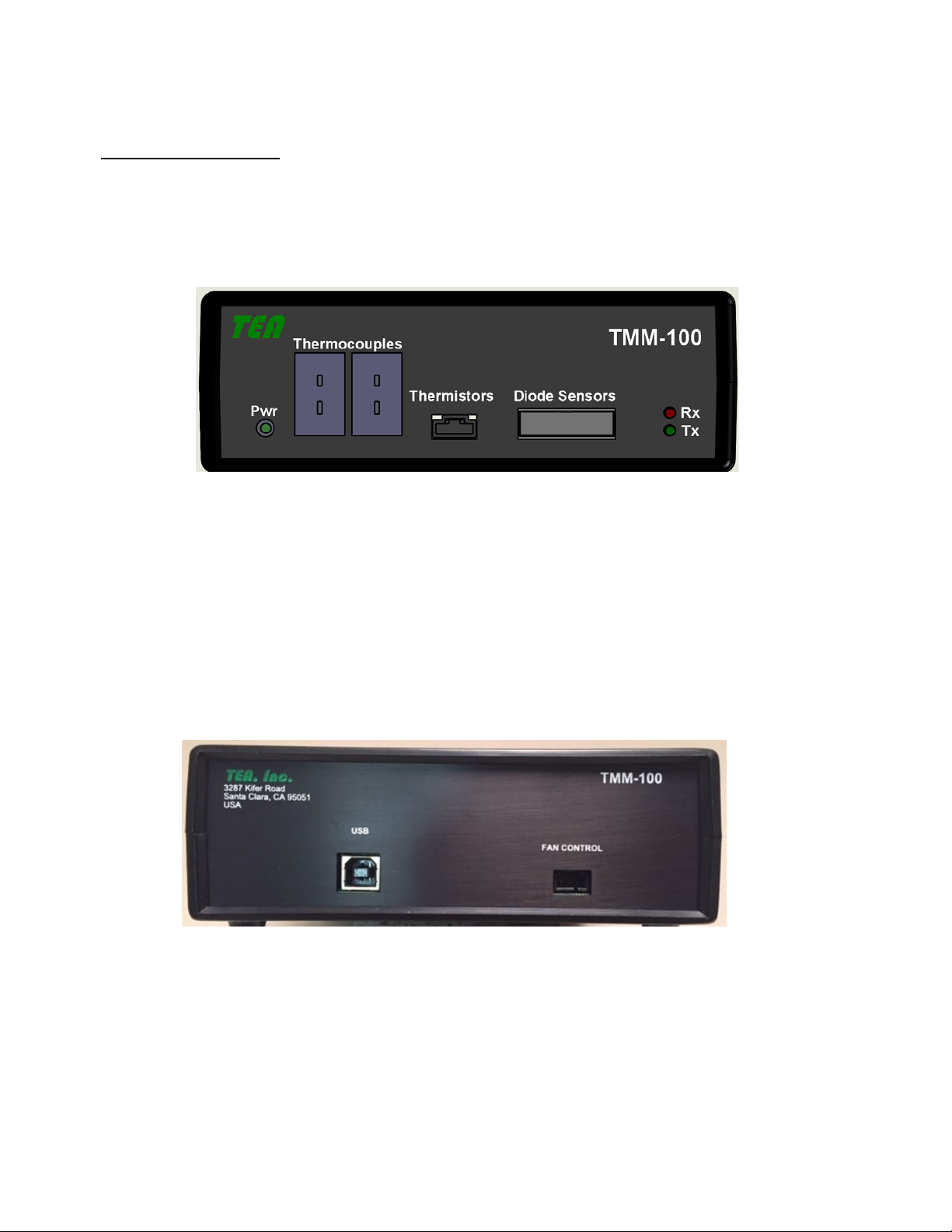
Module Front Panel
The TMM-100 front panel has:
Green Power LED
Red LED for USB Tx Data
Yellow LED for USB Rx Data
2 x 8 connector for Diode connections
2 x Thermistor connector
2 x Thermocouple sockets
The TMM-100 rear panel has:
Standard USB B-type connector
Fan Control connector
SOFTWARE INSTALLATION
See Section 4.
TMM-100 OPERATION
TEA
2-1
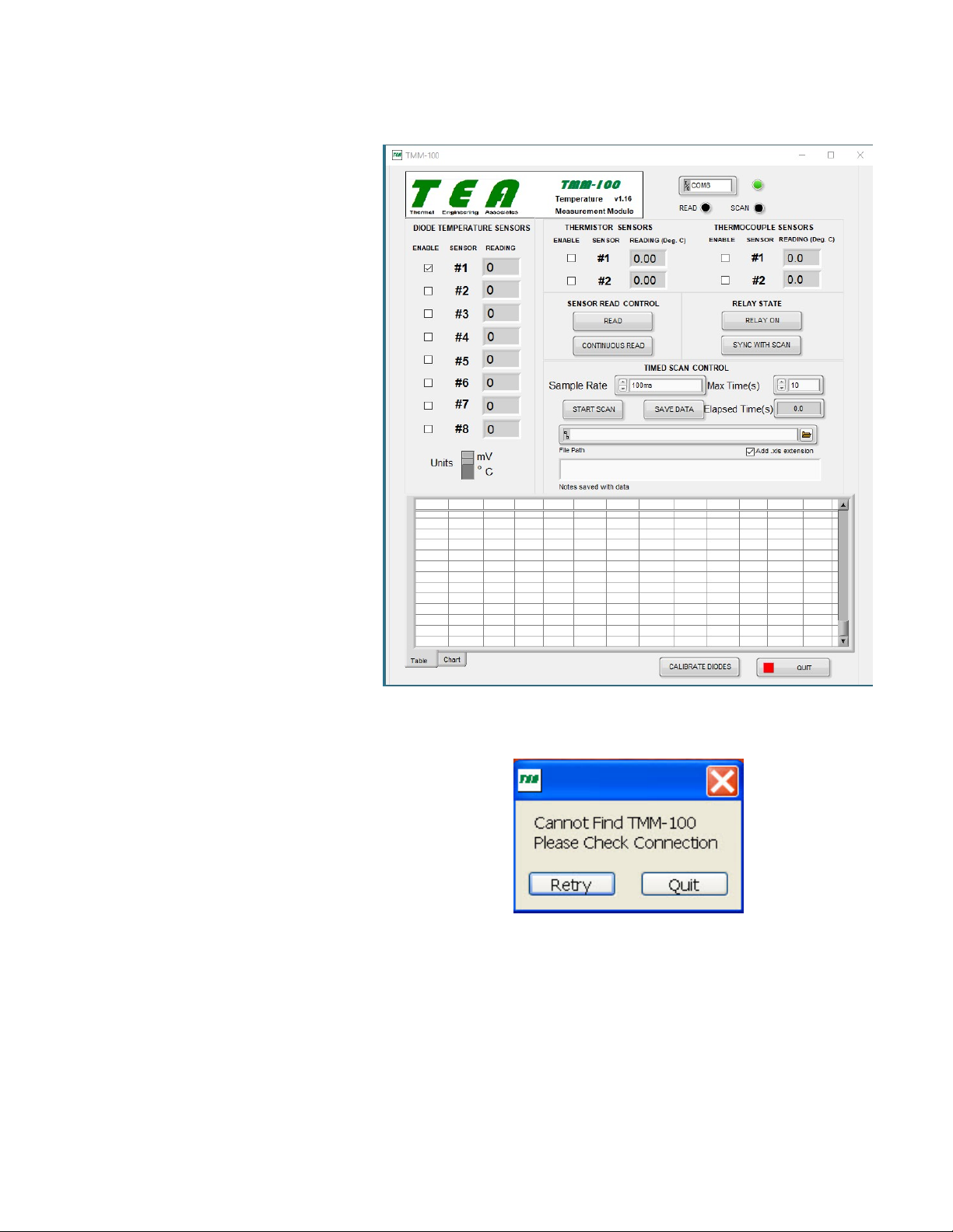
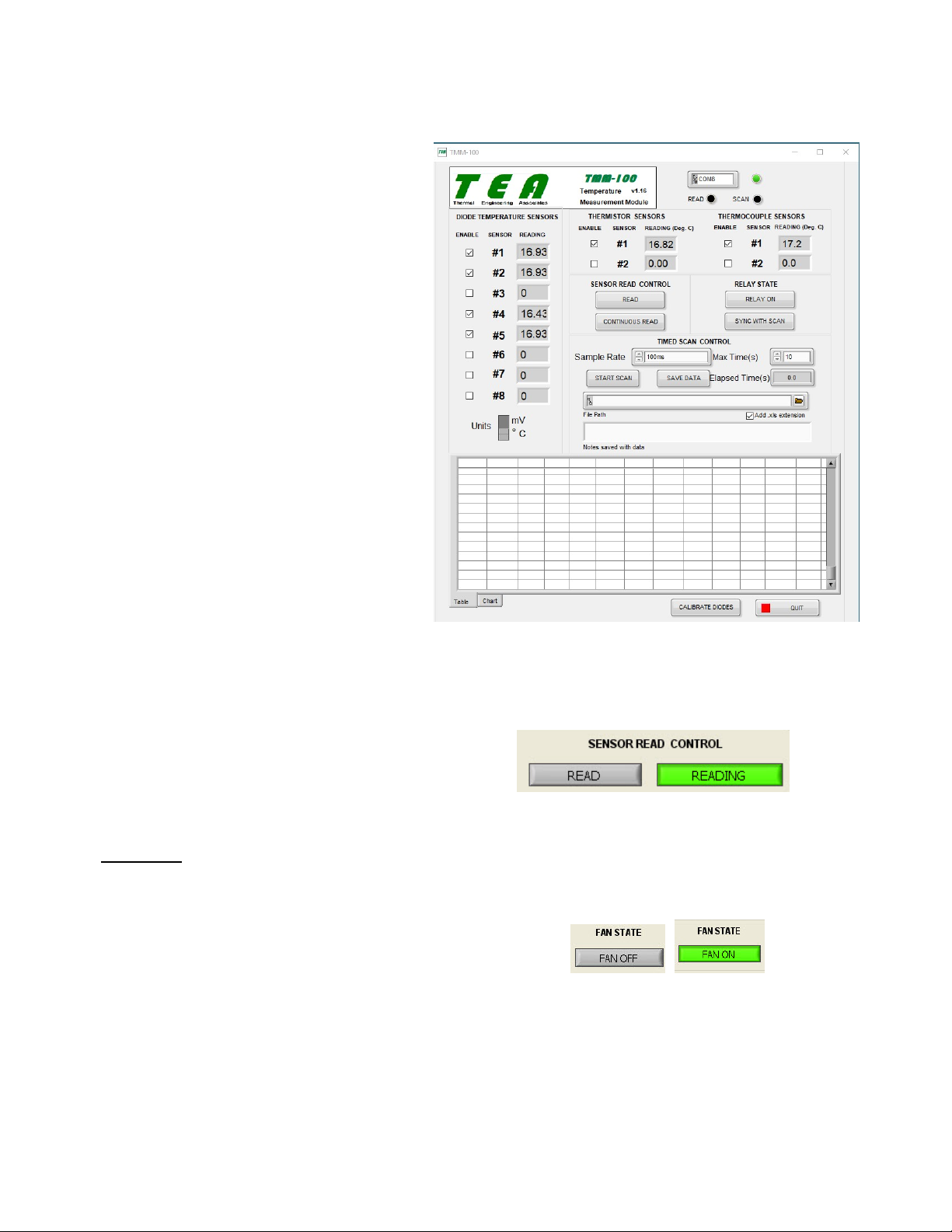
Once the TMM-100.exe file
has been started, the Opening
Screen shown in Figure 1 will
appear.
TMM-100_User_Manual_r4.doc Rev4
If the TMM-100 unit is already
connected to the computer,
the green indicator to the right
of the COM port box (near top
right of the screen) will turn
green and the connected COM
port number will appear in the
port box.
If the TMM-100 unit is not
plugged into the computer, the
indicator next to the COM port
box will be red and a message
box (see Figure 2-2) will ap-
pear. Plug the unit’s USB into
the correct computer port, wait
about 10 seconds, and then
click on the Retry button. After
a few more seconds, the con-
nection indicator will turn
green and the COM port ac-
tually used will appear in the
COM port box.
Figure 2-1 Opening Screen
Figure 2-2 Missing Module Message
The TMM-100 is now ready for use.

TMM-100 OPERATION
TEA
2-2
The TMM-100 Operating
Screen is divided into several
sections:
TMM-100_User_Manual_r4.doc Rev4
Communications Status
Located in the top right (see
Figure 2-1). This section con-
tains the COM port box and
COM port status indicator.
Immediately below are the
status indicators for data
READ and SCAN.
Sensor Selection
Down the left center are the
selection check boxes for Di-
ode Temperature Sensors
numbered 1 through 8. At the
bottom of the diode selection
is a slide to select between di-
ode readings in millivolts and
degrees centigrade.
Immediately below the unit
model number and name are
the Thermistor Sensor selec-
tion check boxes.
Figure 2-3 Sensor Selection
Under the Communications Status section is the Thermocouple Sensor selection check
boxes.
The data will only be read for those sensors that have check marks in their boxes, as shown
in Figure 2-3.
Sensor Read Control
Located in the center right portion of the screen, this second deals with the actual collection
sensor reading collection.
Clicking on the READ button, will cause a single data reading for each selected sensor. The
collected readings will appear in the data box to the right of the individual sensors.
If a sensor is not selected, its data box will contain a “0”, as shown in Figure 2-4.
TMM-100 OPERATION
TEA
TMM-100_User_Manual_r4.doc Rev4 2-3
The Diode Temperature Sensor data
is in terms of millivolts (mV) or de-
grees centigrade (ºC), as determined
by the slide control below the diode
selection column. In order for the di-
ode results to be in centigrade, the
diode voltage must be correlated to
temperature by clicking on the
CALIBRATE DIODES button near
the QUIT button at the bottom right
of the screen. The calibration proce-
dure is described below.
The data for both the Thermistor and
the Thermocouple Sensor is in terms
of ºC.
The CONTINOUS READ button is a
toggle type which is either OFF, as
shown in Figure 2-4 as a grey but-
ton, or ON, as shown in Figure 2-5
as a green button. Clicking on the
button will change the operational
state.
Figure 2-4 Sensor Read
Clicking on the CONTINOUS READ
button will cause the data for all the
selected sensors to be updated
every 100ms.
Figure 2-5 CONTINUOUS READ button
Fan State
Immediately to the right of the SENSOR READ CONTROL section is the FAN STATE sec-
tion. As shown in Figure 2-6, the but-
ton in this section toggles between
FAN OFF and FAN ON states. A relay
connection on the module’s rear panel
allows either for direct control of a
power supply for powering (≤50V, ≤0.75A) a measurement system fan or for providing a digi-
tal signal for fan control circuitry or other measurement environmental system.
Figure 2-6 FAN STATE button
TMM-100 OPERATION
TEA
TMM-100_User_Manual_r4.doc Rev4 2-4
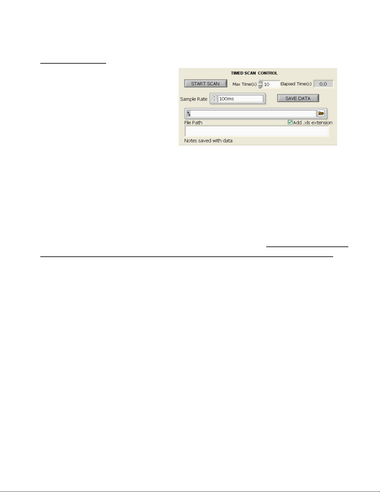
Timed Scan Control
This section is dedicated to the
controls required for collecting data
at a fixed sample rate over some
period of time. Clicking on the
START SCAN button begins the
collection of data from all the se-
lected sensors. When clicked, the
grey START SCAN turns into the
yellow ABORT SCAN button caus-
ing the scan operation to cease.
Figure 2-7 Time Scan Controls
In the top middle of the section is the control for setting the maximum time period from 1 sec-
ond to 10,000 seconds in steps of 1 second. The Max Time in seconds can be set by either
using the up/down arrows on the left of the time set box or by actually entering the max time
in the box. To the right of the setting box is an Elapsed Time indicator box to show where
within the max time the current data scan is.
The Sample Rate selection control has three fixed rates – 10ms, 100ms, and 1s – that can be
selected by clicking the up/down arrow on the left of the data box. The 10ms selection only
works when a single sensor (i.e.,either Diode, Thermistor, or Thermocouple) is selected. The
100ms and 1s selections will work for any combination of selected sensors.
Immediately below the Sample Rate control is the entry box for the datafile path and file-
name.
If the TMM-100 is running on a Windows XP Pro computer, then the full path and filename
must be entered here in order to save the data file.
If the TMM-100 is running on a Windows 7.X, 8.1 or 10 computer, then clicking on the
folder button to the right of the filename area brings up the Windows Save As dialog box
that allows for setting the path but the filename still have to be entered.
If the box is checked for Add .xls extension, then the datafile will be saved with the .xls
suffix. Otherwise, the filename is saved as a text file.
The Notes area is designed to accept up to 4 lines of entered alphanumeric information that
can be use to describe the measurement run operating conditions, information about meas-
urement samples, or other information.
The data, with Notes can be saved after collection by clicking the SAVE DATA button.
TMM-100 OPERATION
TEA
TMM-100_User_Manual_r4.doc Rev4 2-5
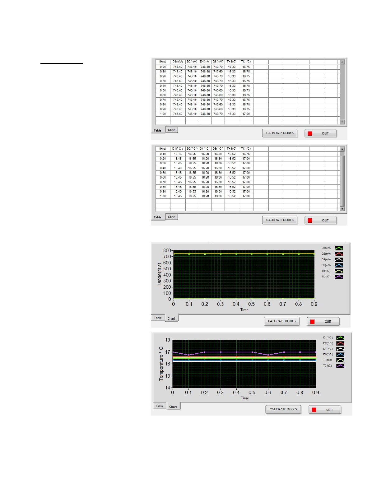
Data Display
In the TIMED SCAN mode,
the collected data is shown
near the bottom of the screen
in either tabular form, as
shown in Figure 2-8, or in
chart form, as shown in
Figure 2-9. The tabs at the
lower left of the data area are
for selection of either Table or
Chart mode.
Figure 2-8 Table Data Display
In the Table mode, the
heating time shown is in the
left-most column (tH(s)), with a
column header name for each
temperature sensor selected.
A few seconds after starting
the scan, data will appear in
the table on a row-by-row
basis. The last data collected
is shown on the last line. The
top table in Figure 2-8 shows
mV for each diode and ºC for
the thermistor and thermo-
couple sensors. Bottom table
shows ºC for all sensors if the
Units slide is in the ºC setting.
Figure 2-9 Chart Data Display
In the Chart mode, the
heating time remains in
seconds but the diode sensor
data is in mV or ºC depending
on the Units slide position.
The vertical scale minimum
and maximum values can be
changed by using the
computer cursor to highlight
the existing number(s) and
then typing in the desired number. The chart will automatically adjust to the new min/max
values.

TMM-100 OPERATION
TEA
TMM-100_User_Manual_r4.doc Rev4 2-6
Diode Calibration
In order for the diode temperature sensors to produce readings in units of ºC, the diode volt-
age must be correlated to temperature. The DIODE SENSOR CALIBRATION routine per-
forms this function. The steps to using this routine are as fol-
lows:
1) Determine which of the other sensors (either Thermistor or
Thermocouple) best represents diode junction temperature
when the diode and other sensor are in the same tempera-
ture ambient. For example, consider the case of a Thermal
Test Chip (TTC) diode sensor and a thermistor that is inte-
grated into heat sink mounted on top of the chip.
2) To insure that both the diode sensor(s) and reference sen-
sor (Thermistor or Thermocouple) are at the same tem-
perature, allow all sensor readings to stabilize (i.e., not
change) over some significant period of time period of time
(for example, 5 to 10 minutes). This can be done by select-
ing the appropriate sensors and then clicking on the CON-
TINOUS READ button described above.
3) Click on the CALIBRATE DIODES button below the data
area bottom right. This will bring up one of the calibration
screens shown in Figure 2-10, the top screen for a single
diode sensor and the bottom screen for multiple diode sen-
sors.
4) If a single diode sensor is being used, enter in the K Factor
(K) value for the diode in units of ºC/mV. (See Diode Temperature Sensing section in
Chapter 3.) For multiple diode sensors, individual K values can be entered or sensor #1
value can be used for all the sensors by checking the box in the lower left of the screen.
Figure 2-10 Diode Calibration
5) The reference temperature sensor used in step 1) above can be selected in the Ref 1
scrolling list. Typically, it is best use a thermistor as a reference because of greater accu-
racy compared to a thermocouple. The same reference sensor can be used for all the se-
lected diode sensors by checking the box in the lower left of the screen.
6) Once all the values have been entered and the appropriate boxes checked, clicking the
SAVE CAL DATA will write the information to a file that will be used whenever the TMM-
100 program is run.

TMM-100 OPERATION
TEA
TMM-100_User_Manual_r4.doc Rev4 2-7
To cease operation of the TMM-100 software, click on the QUIT button at the lower right of
the screen. The unit can be left connected (the front panel green indicator will remain on) to
the computer but will be inactive until the TMM-100 program is again loaded and run.
Exit Program
To cease operation of the TMM-100 software, click on the QUIT button at the lower right of
the screen. The unit can be left connected (the front panel green indicator will remain on) to
the computer but will be inactive until the TMM-100 program is again loaded and run.
TMM-100 APPLICATIONS
TEA
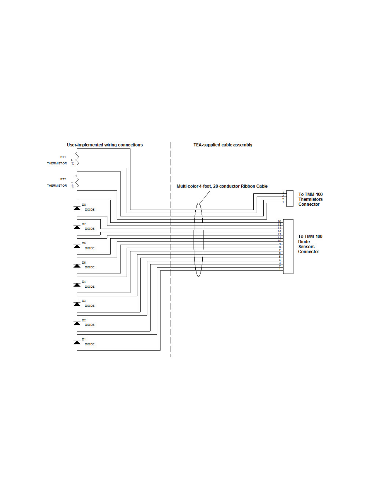
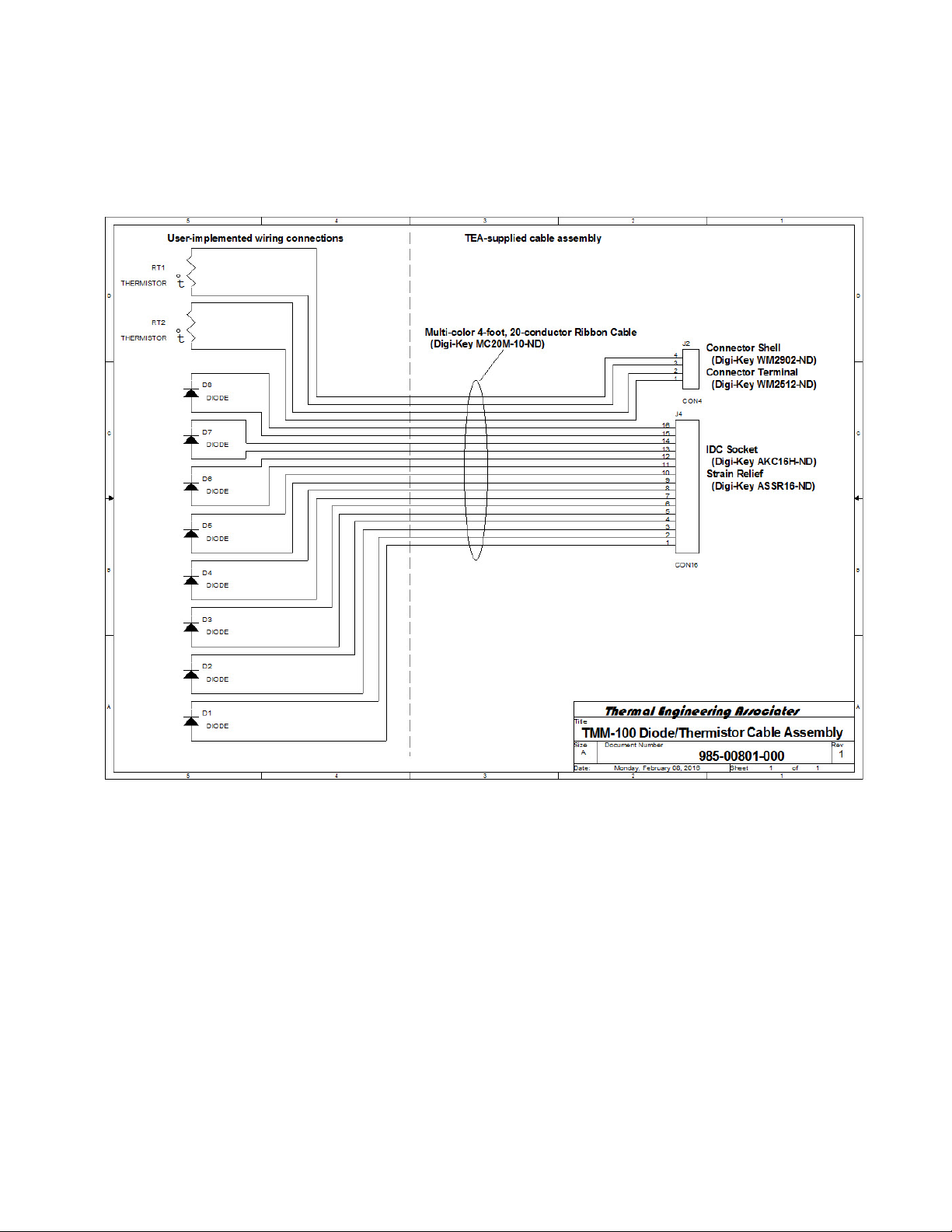
Electrical Connections
The TMM-100 unit is supplied with cables and thermocouples to facilitate user connection to
the various temperature sensors measured by the unit. The user is responsible for making
the electrical connection between the unit and sensors according to the schematic shown in
Figure 3-1.
Note: The supplied temperature sensor cable is rated for use in a
temperature environment below 105ºC.
The ribbon cable conductor color coding follows the standard numerical coding used for re-
sistors –
Figure 3-1
TMM-100_User_Manual_r4.doc Rev3 3-1
TMM-100 APPLICATIONS
TEA
TMM-100_User_Manual_r4.doc Rev3 3-2
Brown 1 Red 2
Orange 3 Yellow 4
Green 5 Blue 6
Violet 7 Grey 8
White 9 Black 0
For example –
For diode D1, anode connects to the first Brown conductor and cathode connects to first
Red conductor.
For diode D5, anode connects to the first White conductor and cathode connects to first
Black conductor.
For diode D6, anode connects to the second Brown conductor and cathode connects to
second Red conductor.
The TMM-100 is designed to used 10KΩ NTC (Negative Temperature Coefficient) thermis-
tors. A surface mount device, such as Murata NCP18XV103J03RB [Digi-Key part # 490-
6944-1-ND] or equivalent, is a small chip that can be mounted to a printed circuit board near
a heat source without impacting air flow.
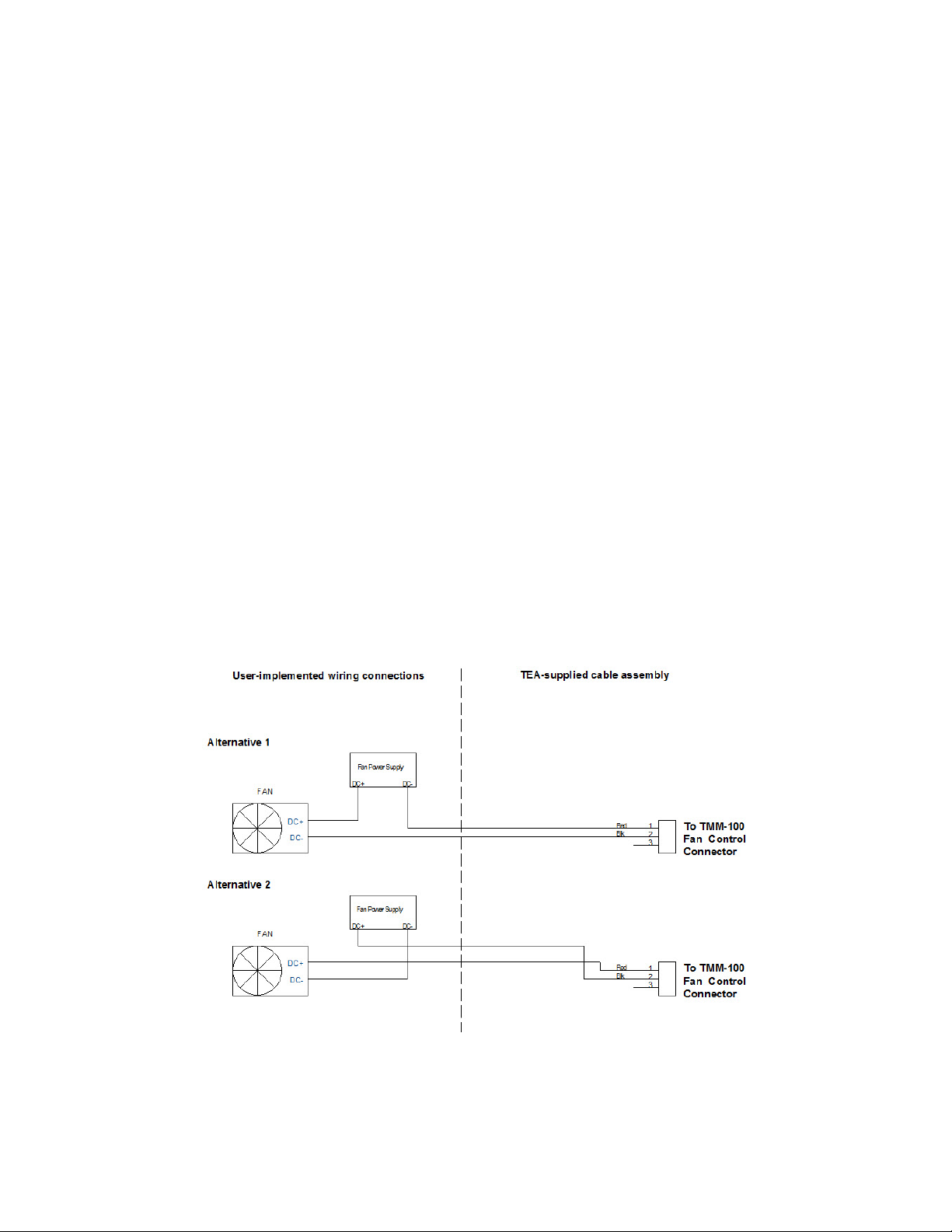
A Fan Control cable is also supplied with the TMM-100. Two alternative wiring configurations
are shown in Figure 3-2. The relay load capability should be limited to <50V and <0.5A.
Figure 3-2
TMM-100 APPLICATIONS
TEA
TMM-100_User_Manual_r4.doc Rev3 3-3
Diode Temperature Sensing
Temperature sensing can be done in either of two ways –
Absolute measurement which requires calibration of a specific diode voltage at a specific
measurement current against a known temperature, or a
Differential measurement which requires the difference between two diode voltage meas-
urements at a specific measurement current multiplied by the K Factor (see Tech Brief TB-
02) to calculate a temperature differential.
Because thermal measurements are typically based on temperature differentials, the latter
approach is typically used. K Factor values at a measurement current of 1mA for TEA’s
Thermal Test Chips are:
TTC-1001 0.5598ºC/mV
TTC-1002 0.5046ºC/mV
The TMM-100 supplies 1mA to each of the diodes connected and measures the voltage for
each of the diodes selected (see Figure 2-8). The diode voltage will decrease as the sensor
heats up. The diode voltage value at equilibrium before heating occurs minus the diode volt-
age at a specified time during the heating produces a voltage difference that is multiplied by
the K Factor to produce a temperature difference. For example using the TTC-1002 –
At equilibrium, VFlo = 0.724V
At some time after heat is applied, VFhi = 0.678V
Voltage difference = 46mV
Temperature change = 46mV x 0.5046ºC/mV = 23.21ºC
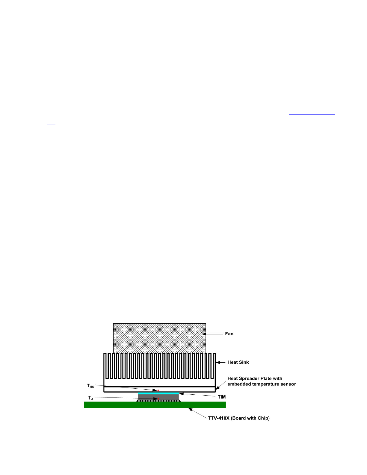
Example Measurement Procedure (TIM Application-Oriented Thermal Resistance)
1) Mount the heat sink solution, including the TIM, on the TTV-410X unit, as shown in Figure
3-3.
Figure 3-3

TMM-100 APPLICATIONS
TEA
TMM-100_User_Manual_r4.doc Rev3 3-4
2) Connect up the power supply and measurement equipment shown in the Apparatus
Setup.
3) Apply the 1.0mA Measurement Current to the diodes used for temperature measurement.
4) Wait for thermal equilibrium to occur - i.e., when the diode voltages stop changing - to re-
cord the diode voltage. Also record the Heat Sink temperature and the ambient tempera-
ture.
5) Apply power to the TTV Heating Resistors by setting the power supply to reach the de-
sired power level.
6) Monitor the diode voltage with the 1.0mA current applied until a steady-state condition has
occurred - i.e., when the diode voltages stop changing - to record the diode voltage and
the Heat Sink temperature.
7) Monitor the heat sink temperature until a steady-state condition has occurred - i.e., when
the diode voltages stopped changing - to record the heat sink temperature
8) Remove the power to the TTV Heating Resistors.
9) Calculate the Thermal resistance from Junction to Heat Sink as follows:
P
TTKVV HSiHSfDfDi )()(
ΘHSJ
ºC/W
where:
VDi and THSi are from step 4
VDf and THSf are from steps 6 and 7
P is from step 5 recorded just before step 6 readings
K is the K Factor value - either the nominal value shown in the TTC Application Manual
(http://www.thermengr.net/TTC/TTC_Manual_R7.pdf) or calibrated as described in the man-
ual (see Chapter 3).
TMM-100 INSTALLATION
TEA
TMM-100_User_Manual_r4.doc Rev3 4-1
The software for installing and running
the TMM-100 is supplied on a USB
Flash Drive. The steps for installing the
software on Windows 7.x or Windows
8.x operating system computer is de-
scribed below.
Step 1. Connect the supplied USB Ca-
ble into the TMM-100 rear panel; DO
NOT plug the other cable end into the
computer’s USB port.
Step 2. After starting the computer, in-
sert the USB Flash Drive into the sys-
tem.
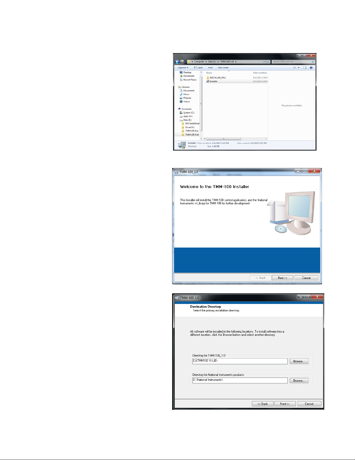
Step 3. Use Windows Explorer to open
the flash drive directory, as shown in
Figure 4-1.
Step 4. Select “Installer” and double-
click to run the program. The window
shown in Figure 4-2 will appear. Click
Next button to proceed.
Step 5. The next window, shown in Fig-
ure 4-3, shows the destination directo-
ries for both the TMM-100 software and
the National Instruments support files.
The operating system will automatically
determine the location and name of
these directories. The user can either
accept the directories presented or
change them to suit specific require-
ments. Click Next button to proceed.
Fig
ure 4.1
Figure 4-2
Figure 4-3
TMM-100 INSTALLATION
TEA
TMM-100_User_Manual_r4.doc Rev3 4-2
Step 6. The next window that appears,
see Figure 4-4, provides a list of files to
be loaded and/or changed. Unless
changes are required, click Next button to
proceed.
The software will then be installed. One or
more information boxes may appear
showing installation progress.
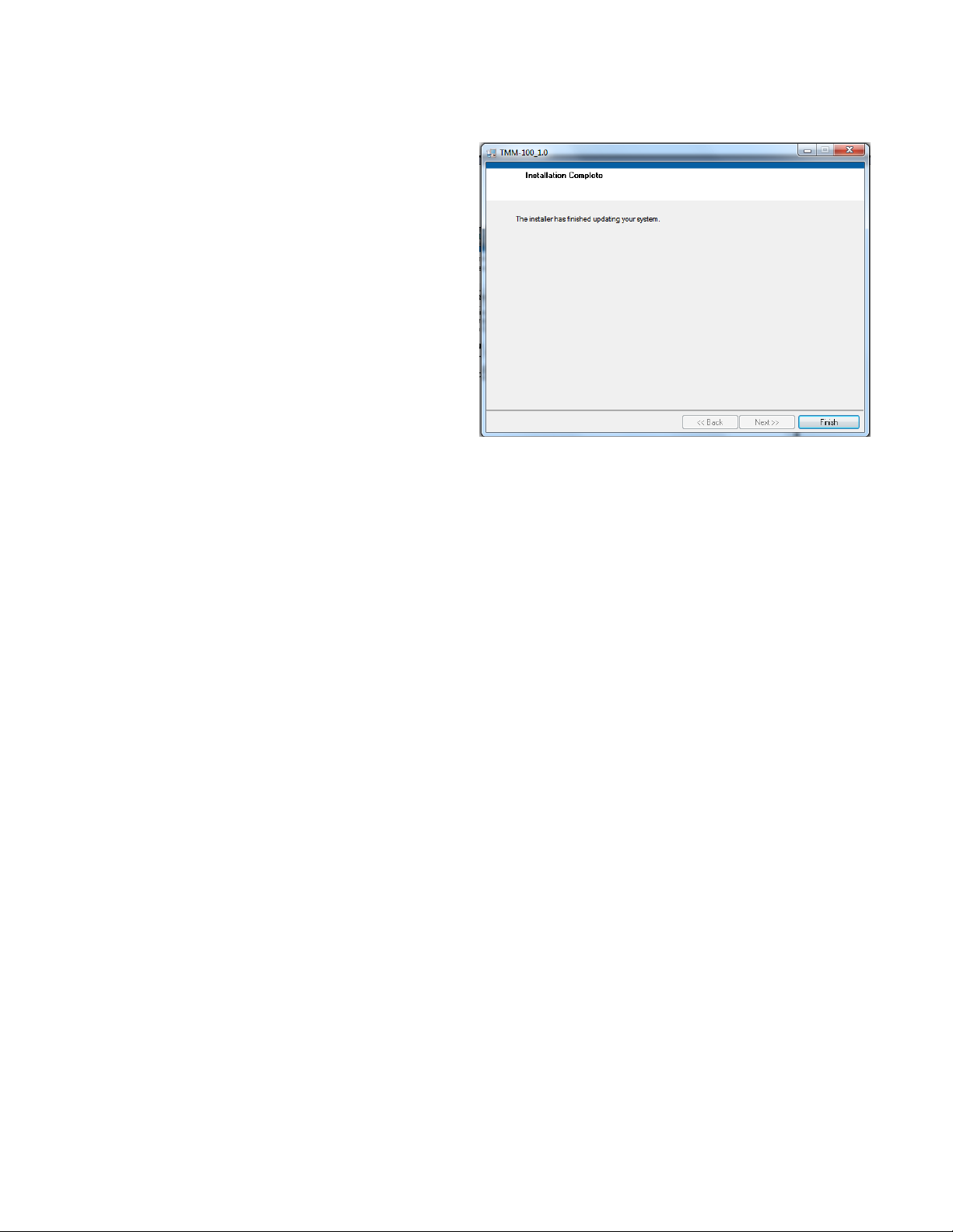
Step 7. When the software installation is
complete, the final window, see Figure 4-
5, will appear. Click Next button to pro-
ceed. Figure 4-4
Step 8. With the installation complete, the last step is to create a desktop icon for easy ac-
cess to the TMM-100 software. Follow the procedure normally used to create a desktop icon.
The TMM-100 can now be connected to the computer. Plug the cable into a computer USB
port and open the TMM-100 software.
TMM-100 Accessories
TEA
Diode/Thermistor Cable Assembly (TEA PN: 985-00801-000)
Thermocouples (TEA PN: 680-00002-001)
Type-T #36 gauge 3-feet long (Omega Engineering (SC-TT-T-36-36)
TMM-100_User_Manual_r4.doc Rev3 5-1
Table of contents
Other TEA Measuring Instrument manuals


