Sonic Sentinel M14-1 User manual
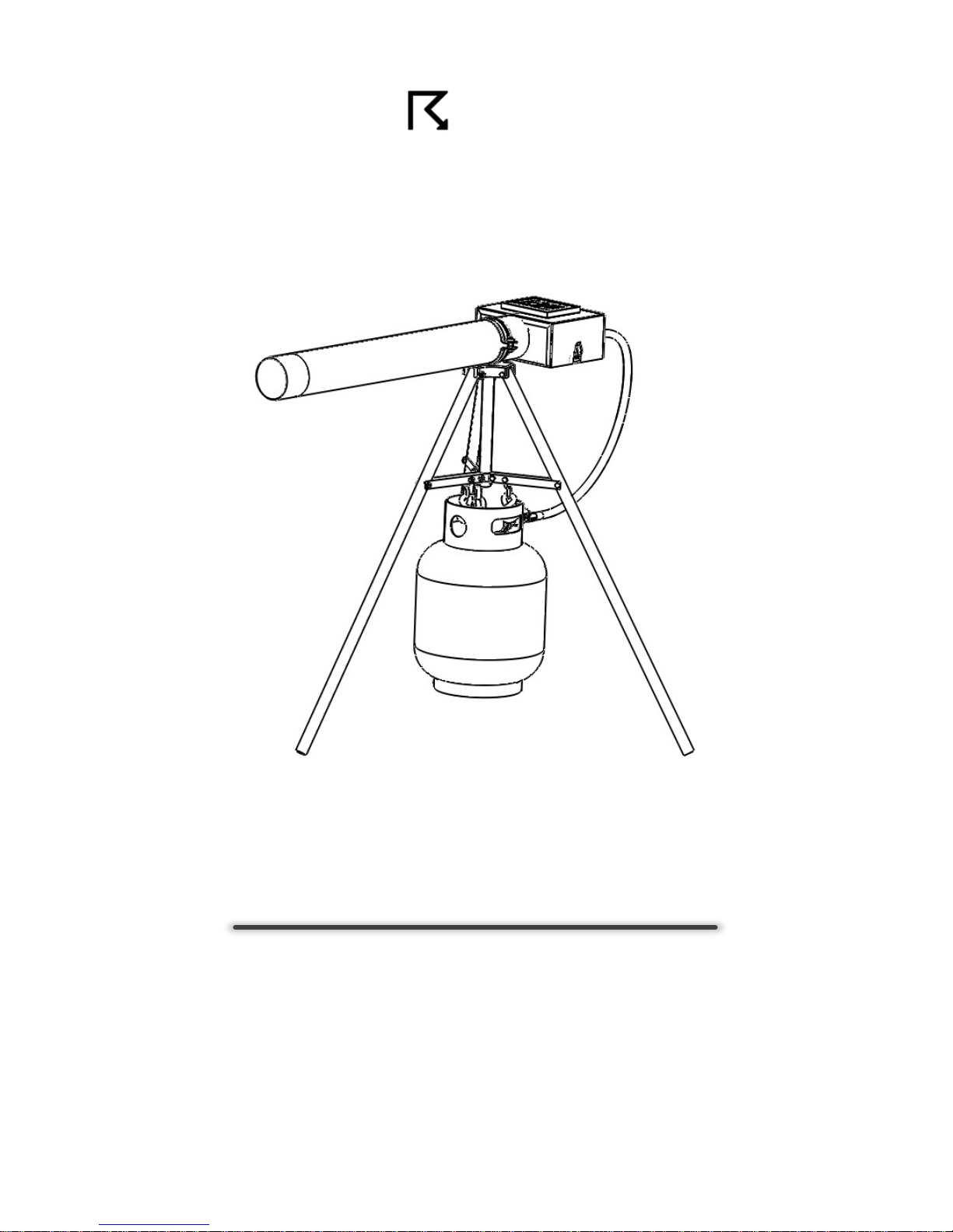
SONIC SENTINELTM
MODEL 14-1
USER’S MANUAL
SONIC SENTINEL, LLC
440 W White Pine Dr
Murray, UT 84123
(385)-275-6222
www.sonicsentinel.com

2 | Page Proudly Designed & Assembled in USA
Table of Contents
1. Introduction pg. 2
2. Safety Precautions pg. 2
3. Product Specifications pg. 3
4. Initial Setup pg. 4–5
5. Operation pg. 6–7
6. Troubleshooting pg. 8
7. Legal pg. 9
8. Parts View & Listing pg. 10–11
9. Warranty pg. 12
10. Compliance pg. 12
1. Introduction
Thank you for purchasing the Sonic Sentinel Model 14-1
Sound Cannon. It is designed to humanely discourage
wildlife from occupying undesirable or unsafe locations.
Preventing such habitation can help avoid property
damage, fines, injury to wildlife, and loss of human life.
2. Safety Precautions
Safe operation of the Sonic Sentinel Model 14-1 Sound
Cannon is the operator's sole responsibility and requires
strict observation of the safety precautions outlined
below. Failure to do so will void the manufacturer's
warranty and could result in property damage, serious
injury, or death.
1. Explosive Propane Gas - For outdoor use only.
No smoking or open flame within 50 feet. Never
point cannon toward people, obstruct the barrel,
or attempt to fire projectiles. Do not alter the LPG
regulator or tank connector in any way. Use only
with OPD equipped tanks of not more than 40lbs.
2. Extreme Sound - Hearing protection must be
worn within 50 feet of cannon while in operation.
3 | Page Proudly Designed & Assembled in USA
3. High Voltage - Do not touch any components
under the black plastic electronics cowling when
the power switch is in the on position or without
first disconnecting the battery terminals.
4. Lead Acid Battery - Do not puncture, short, or
reverse polarity. Replace only with battery of same
type and rating. Dispose of in accordance with local
laws and regulations.
3. Product Specifications
Model 14-1 (M14-1) Specifications
Sound Pressure Level:
130dB @ 1m
Selectable
Firing
Frequency:
30sec – 2hr with
2
Random Modes and
Multi-Shot (1, 2, or 3)
Chronometer
Precision:
+/
- 1%
Operating Temperature
Range:
-5°F – 140°F
(-20°C – 70°C)
LPG Efficiency:
> 20,000 Cycles
(20lb tank)
Electrical Draw:
< 0.2mA Standby
0.0004Ah Per Cycle
Battery Capacity:
(Battery Included)
8Ah
SLA 12VDC
Dimensions
(w/o Tripod)
40in (101.6cm) L
10in (25.4cm) W
5in (12.7cm) H
Weight
(w/o LPG Tank)
Cannon: 22.5lb (10.2kg)
Tripod: 8.0lb (3.6kg)
Shipping: 40.0lb (18.1kg)
Emissions Compliance:
FCC: Part 15, Subpart B
EN: 61000
-6-3:2007
ICES: 001, Issue 4
4 | Page Proudly Designed & Assembled in USA
4. Initial Setup
1. Remove the M14-1 cannon and tripod from their
packaging. Retain packing material for future
transportation needs.
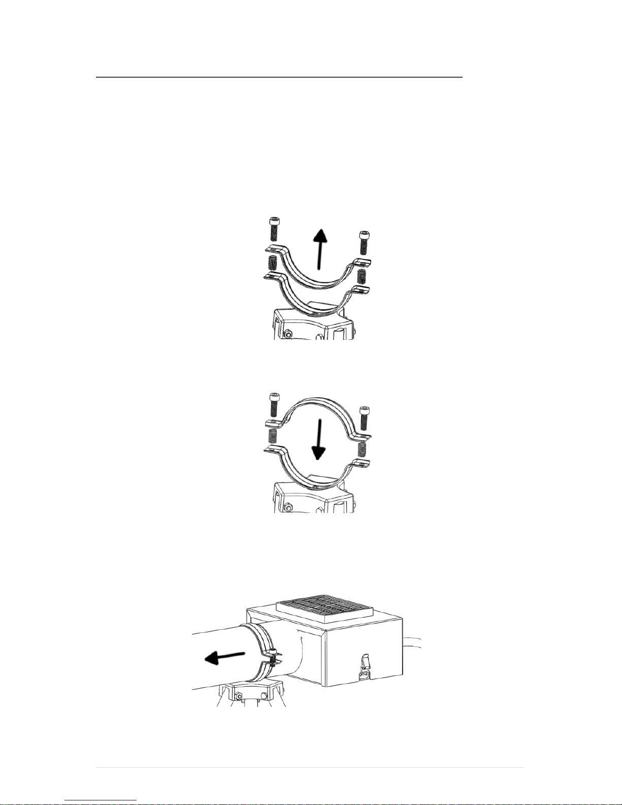
2. Install M14-1 cannon on tripod:
a. Remove bolts and springs from barrel clamp
at top of tripod (Fig. 1).
b. Rotate top half of clamp 180 degrees and
loosely re-install springs and bolts (Fig. 2).
c. Slide barrel of M14-1 cannon into barrel
clamp. Adjust until balanced (approx. 4in
from front of shroud) and level (Fig. 3).
d. Tighten barrel clamp bolts with the provided
6mm wrench.
Figure 2
Figure 1
Figure 3

5 | Page Proudly Designed & Assembled in USA
3. Connect battery:
a. Ensure the M14-1 cannon’s power switch is
in the off (down) position.
b. Remove top shroud and foam battery
insulator. Do not discard the foam insulator!
c. Remove and discard the two, small, plastic
battery terminal insulators.
d. Connect the negative (-) black wire to the
battery’s negative (-) black terminal.
e. Connect positive (+) red wire to the
battery’s positive (+) red terminal.
f. Replace foam battery insulator.
4. Set delay timer to desired firing interval (Fig. 4):
a. OFF: Delay timer is
disabled, but cannon can
be triggered remotely
via activation modules.
b. RANDOM:Cannon will
fire randomly every 1–10min
(RAND1) or every 5–30min (RAND2).
c. Note: Frequencies less than 5min should not be
used in conjunction with our activation modules.
5. Set multi-shot switch (right of delay timer, Fig. 5)
to desired shot count: center=1, up=2, or down=3.
6. Reinstall top shroud. Ensure that the solar panel
wires remain connected and fold into the space
between the battery and barrel.
7. Connect propane tank (not included):
a. Suspend a standard, user provided, 20lb
propane tank from the M14-1 tripod’s 3 S-
hooks with valve opening facing aft.
Note: 30-40lb tanks can be used in conjunction
only with Sonic Sentinel’s tripod extension kit.
b. Securely fasten the M14-1 regulator’s OPD
connector to propane tank valve.
Figure 4Figure 5

6 | Page Proudly Designed & Assembled in USA
5. Operation
1. Select a suitable outdoor location for the
M14-1 cannon that meets the following criteria:
a. On level, solid ground to prevent tipping
Note: Optional tripod feet are available to
support the M14-1 cannon on unstable surfaces.
b. Free of debris and combustible material
c. In direct sunlight and free from overhead
obstructions shading the solar panel
Note: For sustained operation, the solar panel of
the M14-1 cannon should receive at least 5 hours
of direct sunlight each day.
d. Clearly visible to passers-by
e. Facing downwind relative to prevailing winds
f. Away from residential or other sound
sensitive areas
Note: The M14-1 cannon is capable of producing
sound levels that may violate local noise
ordinances. Ensuring legal operation of the M14-1
is the operator's sole responsibility and should
only be conducted only in accordance with local
laws and regulations.
g. As close to the desired deterrent zone as
possible taking the above factors into
consideration.
2. Ensure that all of the following conditions are met
before proceeding:
a. Barrel of M14-1 is not obstructed and is
pointed away from people and objects
b. Propane tank connection is secure
c. No sources of ignition are present
d. Any persons within 50 feet of cannon are
wearing ear protection.

7 | Page Proudly Designed & Assembled in USA
3. Open propane tank valve and turn power switch on
(up).
Note: There is a 30 second power-up delay, during
which the M14-1 cannon will not activate, to provide
adequate time to safely clear the immediate area.
Note: Battery voltage must be above 12 volts in order
for the M14-1 cannon to initialize.
4. Following the power-up delay, the M14-1 cannon
will begin firing at the delay timer interval set
during initial setup.
Note: There is a 30 second post-fire delay, during
which the M14-1 cannon will not activate, to prevent
wasteful and potentially hazardous continuous firing.
5. When in the “OFF” position, the delay timer is
disabled, but the cannon can still be triggered
remotely via activation modules.
Note: When the M14-1 cannon is used in conjunction
with any of Sonic Sentinel’s activation modules, the
delay timer is reset after each commanded detonation.
6. Change the location and detonation frequency of
the M14-1 cannon frequently to prevent wildlife
from habituating to its effect.
Caution:Always power down the M14-1 cannon before
removing the top shroud to update the delay timer!
7. Periodically clean the solar panel using a damp cloth.
Note: Regularly remove any snow accumulation or
other debris from the solar panel to ensure the battery
stays charged.
8. Close propane tank valve and turn power switch off
(down) when not in use to prevent accidental firing.
Note: When storing the M14-1 cannon for long periods
(> 1 week), disconnect the battery to prevent discharge.
8 | Page Proudly Designed & Assembled in USA
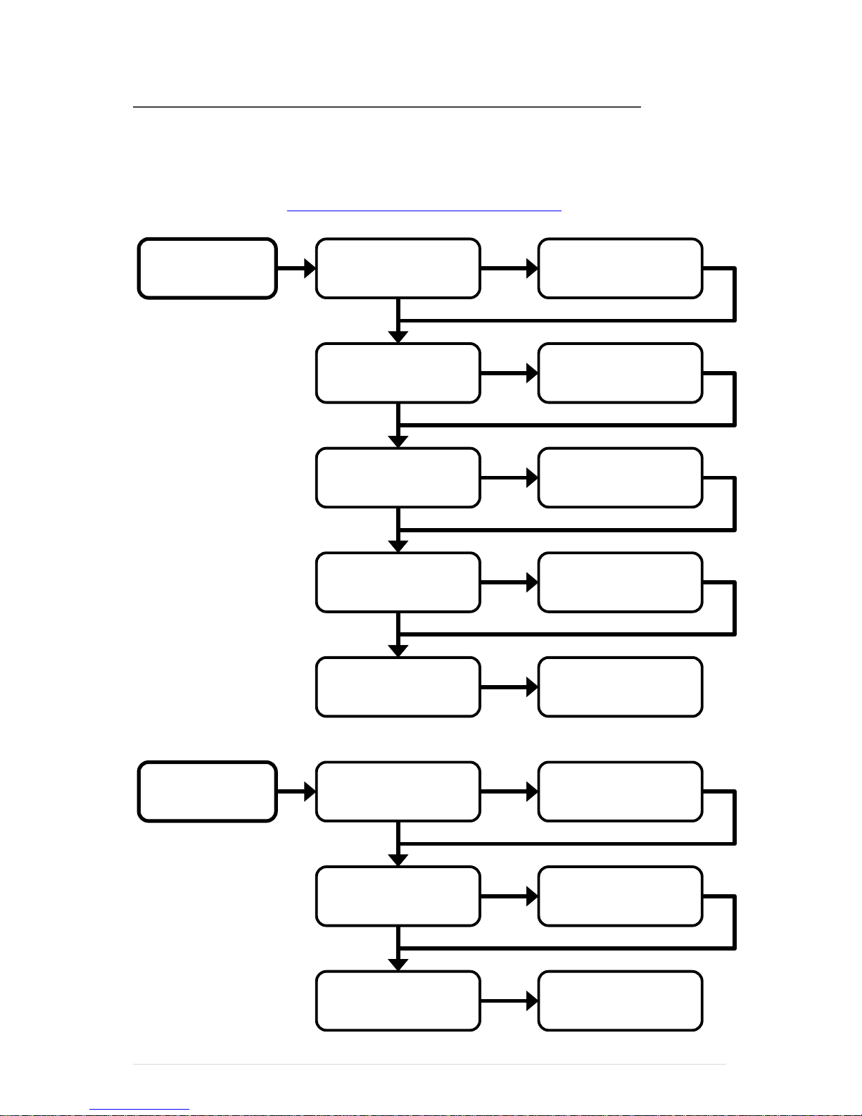
6. Troubleshooting
The following flowchart outlines several common
problems and their solutions. For other questions,
please contact support@sonicsentinel.com.
Cannon does
not fire
Open gas valve
& turn power on
Power switch &
gas valve on?
Is gas injection
(hissing) heard?
Check propane
tank gas level
NO
NO
YES
NO
Is ignition
(buzzing) heard?
Is the barrel
obstructed?
Does cannon
fire?
Is propane
tank level low?
Are conditions
windy?
Does cannon
fire loudly?
Check battery
voltage > 12V
Power off M14-1
and clear barrel
Contact support
Replace
propane tank
Point barrel
downwind
Contact Support
NO
YES
YES
YES
Cannon is
not loud
YES
YES
NO
NO
NO
NO

9 | Page Proudly Designed & Assembled in USA
7. Legal
Applicability:
1. These Terms apply to any transaction between Sonic
Sentinel, LLC (hereafter known as "Seller") and its
customers (hereafter known as "Buyer" or "Buyers").
The Terms are integral to any purchase agreement,
invoice, order form, or other document(s) pertaining to
the sale of, or the offer to sell, Seller's products. The
placement of any order for Seller's products and/or the
use of Seller's products implies an agreement to these
Terms in full.
2. Buyer's ability to purchase and/or use Seller’s products
is expressly predicated on Buyer's acceptance of these
terms and conditions. Any purchase of product shall be
considered a contractual agreement by Buyer to Seller's
Terms as provided here: www.sonicsentinel.com/legal.
Limitation of Seller’s Liability:
1. Seller shall not be liable for any general or special
damages arising from the use or misuse of the Model
14-1 Sound Cannon and its accessories (hereafter
known as “Product”). No warranty is provided by Seller
beyond replacement due to defects in manufacturing
and is limited to a refund of the purchase price. Seller's
warranty is exclusive of all other warranties, and any
implied warranty of merchantability and/or implied
warranty of fitness for a purpose is hereby disclaimed.
2. Buyer is solely responsible for determining the suitability
of Seller's products for a purpose intended by Buyer or
Buyer's customers. Seller has tested products only as
explained in Seller's product specifications and this
manual. Buyer agrees not to use Seller's products in any
way not specified by Seller's instructions and product
descriptions. Buyer shall assume all responsibility for
any claims, losses, damages, demands, and expenses
incurred by the use or misuse of Seller's products,
including the incorporation of Seller's products into other
goods for sale by the Buyer.
3. Seller does not authorize or otherwise endorse Buyer to
make any modification or change to Product. Any
changes or modifications made by Buyer to Product,
which are not expressly approved by Seller in writing,
shall render any and all warranties invalid.

10 | Page Proudly Designed & Assembled in USA
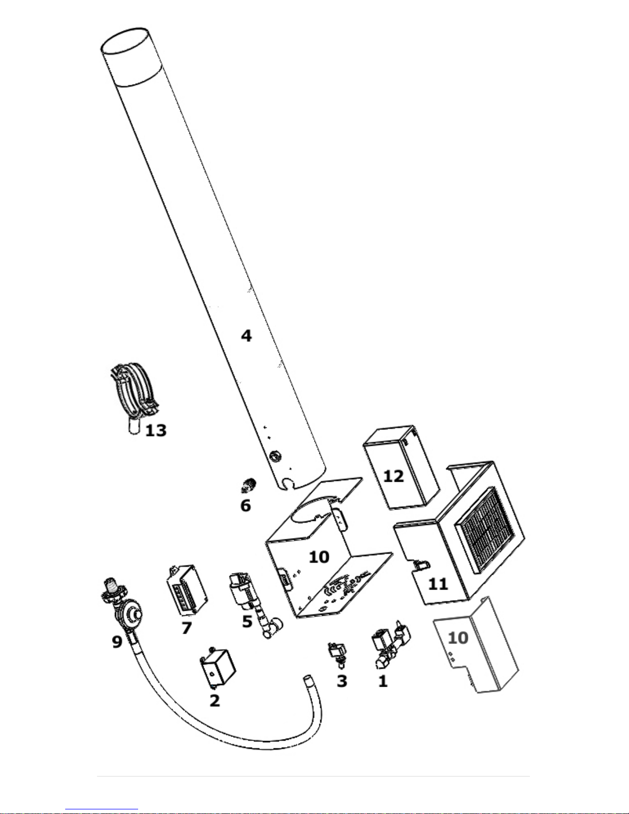
8. Parts View & Listing
The following M14-1 replacement individual parts and
assemblies are available:
Parts Part #
1. Injector Assembly 00006
2. Ignition Control Module 00007
3. Power Switch 00008
4. Barrel Assembly 00009
5. Coil Assembly 00010
6. Spark Plug 00011
7. Solar Controller 00012
8. Wiring Harness*00013
9. Propane Regulator 00014
10. Lower Shroud & Cowling 00015
11. Upper Shroud 00016
12. 12VDC 8Ah Battery 00017
13. Tripod Barrel Clamp 00018
The following M14-1 accessories are available:
Accessories*Part #
1. Tripod Extension (24in) 00020
2. Tripod Feet (Set of 3) 00021
3. Nighttime Deactivation 00022
4. Battery Charger (12VDC) 00023
5. Propane Level Sensor 00024
6. Programmable Timer 00025
7. 360° Rotating Tripod 00026
The following M14-1 activation modules are available:
Activation Modules*Part #
1. Push-Button Remote Controls 00030–32
2. XBee Radio Modules 00033–36
3. Motion Detection Modules 00037–39
To purchase parts and accessories, or for more
information, visit http://www.sonicsentinel.com.
*Not Pictured
11 | Page Proudly Designed & Assembled in USA

12 | Page Proudly Designed & Assembled in USA
9. Warranty
Seller warrants Product against defects in materials or
workmanship for a period of 1 year from the date of
original sale. No warranty is provided by Seller beyond
replacement due to defects in manufacturing and is
limited to a refund of the purchase price. Seller's
warranty is exclusive of all other warranties, and any
implied warranty of merchantability and/or implied
warranty of fitness for a purpose is hereby disclaimed.
10. Compliance
FCC (Federal Communications Commission):This
equipment has been tested and found to comply with the
limits for a Class B digital device, pursuant to part 15 of
the FCC Rules. These limits are designed to provide
reasonable protection against harmful interference in
residential or commercial installations. This equipment
generates, uses, and can radiate radio frequency energy
and, may cause harmful radio interference.
IC (Industry Canada):This equipment has been tested
and found to comply with the limits for a Class B digital
device, pursuant to Industry Canada ICES-001, Issue 4.
EN (European Norm): This equipment has been tested
and found to comply with the limits defined by EN 61000-
6-3:2007 for electromagnetic emissions in light industrial
applications.
Table of contents


