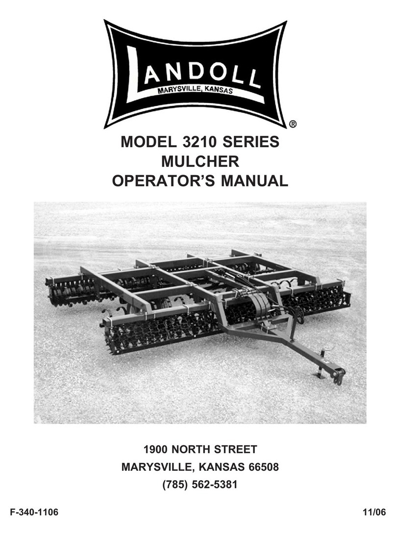
Landoll Brillion PAT 10 User manual


i
Table of Contents
1 Introduction and Safety Information
Introduction . . . . . . . . . . . . . . . . . . . . . . . . . . . . . . . . . . . . . . . . . . . . . . . . . . . . . . . . . . . . . . . . . . 1-1
Description of Unit . . . . . . . . . . . . . . . . . . . . . . . . . . . . . . . . . . . . . . . . . . . . . . . . . . . . . . . . . 1-1
Owner Assistance . . . . . . . . . . . . . . . . . . . . . . . . . . . . . . . . . . . . . . . . . . . . . . . . . . . . . . . . .1-1
Warranty Registration . . . . . . . . . . . . . . . . . . . . . . . . . . . . . . . . . . . . . . . . . . . . . . . . . . . . . .1-1
Safety . . . . . . . . . . . . . . . . . . . . . . . . . . . . . . . . . . . . . . . . . . . . . . . . . . . . . . . . . . . . . . . . . . . . . . . 1-2
Transporting Safety . . . . . . . . . . . . . . . . . . . . . . . . . . . . . . . . . . . . . . . . . . . . . . . . . . . . . . . . 1-2
Attaching, Detaching and Storage . . . . . . . . . . . . . . . . . . . . . . . . . . . . . . . . . . . . . . . . . . . . . 1-2
Maintenance Safety . . . . . . . . . . . . . . . . . . . . . . . . . . . . . . . . . . . . . . . . . . . . . . . . . . . . . . . .1-3
Protective Equipment . . . . . . . . . . . . . . . . . . . . . . . . . . . . . . . . . . . . . . . . . . . . . . . . . . . . . .1-3
High Pressure Fluid Safety . . . . . . . . . . . . . . . . . . . . . . . . . . . . . . . . . . . . . . . . . . . . . . . . . . 1-3
Prepare for Emergencies . . . . . . . . . . . . . . . . . . . . . . . . . . . . . . . . . . . . . . . . . . . . . . . . . . . 1-3
Tire Safety . . . . . . . . . . . . . . . . . . . . . . . . . . . . . . . . . . . . . . . . . . . . . . . . . . . . . . . . . . . . . . . 1-3
Safety Chain . . . . . . . . . . . . . . . . . . . . . . . . . . . . . . . . . . . . . . . . . . . . . . . . . . . . . . . . . . . . . 1-4
Decals . . . . . . . . . . . . . . . . . . . . . . . . . . . . . . . . . . . . . . . . . . . . . . . . . . . . . . . . . . . . . . . . . . 1-5
2 Assembly
Frame and Rotor . . . . . . . . . . . . . . . . . . . . . . . . . . . . . . . . . . . . . . . . . . . . . . . . . . . . . . . . . . 2-2
Drawbar Installation . . . . . . . . . . . . . . . . . . . . . . . . . . . . . . . . . . . . . . . . . . . . . . . . . . . . . . . . 2-4
Wheel Arm Assembly . . . . . . . . . . . . . . . . . . . . . . . . . . . . . . . . . . . . . . . . . . . . . . . . . . . . . . 2-6
Hydraulic System Installation: . . . . . . . . . . . . . . . . . . . . . . . . . . . . . . . . . . . . . . . . . . . . . . . . 2-8
Lift Hydraulic Circuit Installation . . . . . . . . . . . . . . . . . . . . . . . . . . . . . . . . . . . . . . . . . . . . . . 2-8
LED Lamp and Harness Installation . . . . . . . . . . . . . . . . . . . . . . . . . . . . . . . . . . . . . . . . . . 2-10
Weight Kit - Optional . . . . . . . . . . . . . . . . . . . . . . . . . . . . . . . . . . . . . . . . . . . . . . . . . . . . . .2-12
3 Operation
Operation of the Aerator . . . . . . . . . . . . . . . . . . . . . . . . . . . . . . . . . . . . . . . . . . . . . . . . . . . .3-1
Aerator Preparation . . . . . . . . . . . . . . . . . . . . . . . . . . . . . . . . . . . . . . . . . . . . . . . . . . . . . . . . 3-1
Attaching to the Tractor . . . . . . . . . . . . . . . . . . . . . . . . . . . . . . . . . . . . . . . . . . . . . . . . . . . . .3-1
Drawbar Jack Positions . . . . . . . . . . . . . . . . . . . . . . . . . . . . . . . . . . . . . . . . . . . . . . . . . . . . . 3-2
Transport Lock . . . . . . . . . . . . . . . . . . . . . . . . . . . . . . . . . . . . . . . . . . . . . . . . . . . . . . . . . . . 3-4
Field Operation . . . . . . . . . . . . . . . . . . . . . . . . . . . . . . . . . . . . . . . . . . . . . . . . . . . . . . . . . . . 3-4
Transporting . . . . . . . . . . . . . . . . . . . . . . . . . . . . . . . . . . . . . . . . . . . . . . . . . . . . . . . . . . . . . 3-4
Parking the Aerator . . . . . . . . . . . . . . . . . . . . . . . . . . . . . . . . . . . . . . . . . . . . . . . . . . . . . . . . 3-4
LED 7-Pin AG Connector . . . . . . . . . . . . . . . . . . . . . . . . . . . . . . . . . . . . . . . . . . . . . . . . . . . 3-5
Transport . . . . . . . . . . . . . . . . . . . . . . . . . . . . . . . . . . . . . . . . . . . . . . . . . . . . . . . . . . . . . . . . 3-5

ii
4 Maintenance
General Torque Specifications . . . . . . . . . . . . . . . . . . . . . . . . . . . . . . . . . . . . . . . . . . . . . . . 4-1
Hydraulic Fitting Torque Specifications . . . . . . . . . . . . . . . . . . . . . . . . . . . . . . . . . . . . . . . . . 4-2
Tires . . . . . . . . . . . . . . . . . . . . . . . . . . . . . . . . . . . . . . . . . . . . . . . . . . . . . . . . . . . . . . . . . . . . 4-3
Lubrication . . . . . . . . . . . . . . . . . . . . . . . . . . . . . . . . . . . . . . . . . . . . . . . . . . . . . . . . . . . . . . . 4-3
Hydraulic System . . . . . . . . . . . . . . . . . . . . . . . . . . . . . . . . . . . . . . . . . . . . . . . . . . . . . . . . . . 4-3
Rotor Bearing Maintenance . . . . . . . . . . . . . . . . . . . . . . . . . . . . . . . . . . . . . . . . . . . . . . . . . . 4-5
Rotor Blade . . . . . . . . . . . . . . . . . . . . . . . . . . . . . . . . . . . . . . . . . . . . . . . . . . . . . . . . . . . . . . 4-6
Storage . . . . . . . . . . . . . . . . . . . . . . . . . . . . . . . . . . . . . . . . . . . . . . . . . . . . . . . . . . . . . . . . . 4-7
5 General Reference and Specifications

F-948R0 1-1
Chapter 1
Introduction and Safety Information
Introduction
The implement described in this manual has been
designed with care and built by skilled workers using
quality materials and processes. Proper assembly and
maintenance will provide you with satisfactory use for
seasons to come.
DANGER
Description of Unit
The Brillion Aerator is designed to aerate the ground by
putting slots in the ground to improve the absorption of
water and loosen the soil to improve root growth.
Using this Manual
This manual will familiarize you with safety, assembly,
operation, adjustment, and maintenance. Read this
manual and follow the recommendations to help ensure
safe and efficient operation.
• The information in this manual is current at time of
printing. Some parts may have changed to assure top
performance.
• Location reference: Right and Left designations in this
manual are determined by facing the direction the
implement will travel during field operation, unless
otherwise stated.
Owner Assistance
If customer service or repairs are needed, contact your
Brillion dealer. They have trained personnel, parts and
service equipment specially designed for Brillion
products. Your implement’s parts should only be replaced
with Brillion parts. If items covered in this manual are not
understood, contact your local Brillion Dealer.
Warranty Registration
Brillion Farm Equipment, by Landoll, shall have no
warranty obligation unless each product is registered
within 10 days of retail purchase, using the Landoll
Corporation Ag Products on-line registration process.
Please refer to the Ag Products Policy and Procedures
Manual, accessible at www.landoll.com for step by step
instructions regarding product registration.
Enter your product information below for quick reference.
MODEL NUMBER
SERIAL NUMBER
DATE OF PURCHASE
Refer to the ID plate as shown. See Figure 1-1.
Figure 1-1 ID Plate
Read this entire manual before attempting to
assemble, adjust or operate this implement.
Failure to comply with this warning can result in
personal injury or death, damage to the
implement or its components and inferior
operation.

1-2 F-948R0
INTRODUCTION AND SAFETY INFORMATION
Safety
NOTE
Investigation has shown that nearly 1/3 of all farm
accidents are caused by careless use of machinery.
Insist that all people working with you or for you abide by
all safety instructions.
You will find various types of safety information on the
following pages and on the implement decals (signs)
attached to the implement. This section explains their
meaning.
NOTICE
CAUTION
WARNING
DANGER
NOTE
You should read and understand the information
contained in this manual and on the implement decals
before you attempt to operate or maintain this equipment.
Examine safety decals and be sure you have the correct
safety decals for the implement. See Figure 1-3.
Order replacement decals through your Brillion dealer.
Keep these signs clean so they can be observed readily.
It is important to keep these decals cleaned more
frequently than the implement. Wash with soap and water
or a cleaning solution as required.
Replace decals that become damaged or lost. Also, be
sure that any new implement components installed
during repair include decals which are assigned to them
by the manufacturer.
When applying decals to the implement, be sure to clean
the surface to remove any dirt or residue. Where
possible, sign placement should protect the sign from
abrasion, damage, or obstruction from mud, dirt, oil etc.
DANGER
Transporting Safety
IMPORTANT
It is the responsibility of the owner/operator to
comply with all state and local laws.
When transporting the implement on a road or highway,
use adequate warning symbols, reflectors, lights and
slow moving vehicle sign as required. Slow moving
tractors and towed implements can create a hazard when
driven on public roads. They are difficult to see,
especially at night.
Do not tow an implement that, when fully loaded, weighs
more than 1.5 times the weight of the towing vehicle.
Carry reflectors or flags to mark the tractor and
implement in case of breakdown on the road.
Do not transport at speeds over 20 MPH under good
conditions. Never travel at a speed which does not allow
adequate control of steering and stopping. Reduce
speed if towed load is not equipped with brakes
Avoid sudden stops or turns because the weight of the
implement may cause the operator to lose control of the
tractor. Use a tractor heavier than the implement.
Use caution when towing behind articulated steering
tractors; fast or sharp turns may cause the implement to
shift sideways.
Keep clear of overhead power lines and other
obstructions when transporting. Know the transport
height and width of your implement.
Attaching, Detaching and Storage
• Do not stand between the tractor and implement when
attaching or detaching implement unless both are
blocked from moving.
• Block implement so it will not roll when unhitched from
the tractor.
Special notice - read and thoroughly understand.
Proceed with caution. Failure to heed caution
may cause injury to person or damage product.
Proceed with caution. Failure to heed warning will
cause injury to person or damage product.
Proceed with extreme caution. Failure to heed
notice will cause injury or death to person and/or
damage product.
• Do not allow anyone to ride on the tractor or
implement. Riders could be struck by foreign
objects or thrown from the implement.
• Never allow children to operate equipment.
• Keep bystanders away from implement during
operation.

INTRODUCTION AND SAFETY INFORMATION
F-948R0 1-3
Maintenance Safety
• Block the implement so it will not roll when working on
or under it to prevent injury.
• Do not make adjustments or lubricate the machine
while it is in motion.
• Make sure all moving parts have stopped.
• Understand the procedure before doing the work. Use
proper tools and equipment.
Protective Equipment
• Wear protective clothing & equipment appropriate for
the job. Avoid loose fitting clothing.
• Because prolonged exposure to loud noise can cause
hearing impairment or hearing loss, wear suitable
hearing protection, such as earmuffs or earplugs.
High Pressure Fluid Safety
Escaping fluid under pressure can be nearly invisible and
have enough force to penetrate the skin causing serious
injury. Use a piece of cardboard, rather than hands, to
search for suspected leaks.
Any fluid injected into the skin must be surgically
removed within a few hours or gangrene may result.
Avoid the hazard by relieving pressure before
disconnecting hydraulic lines.
Prepare for Emergencies
• Keep a First Aid Kit and Fire Extinguisher handy.
• Keep emergency numbers for the doctor, ambulance,
hospital and fire department near the phone.
Tire Safety
Tire changing can be dangerous and should be
performed by trained personnel using correct tools and
equipment.
When inflating tires, use a clip-on chuck and extension
hose long enough to allow you to stand to one side, not in
front of or over the tire assembly. Use a safety cage if
available.
When removing and installing wheels use
wheel-handling equipment adequate for the weight
involved.

1-4 F-948R0
INTRODUCTION AND SAFETY INFORMATION
Safety Chain
Use the safety chain to help control drawn machinery
should it separate.
Use a chain with a strength rating equal to or greater than
the gross weight of towed machinery, which is 11,000
pounds minimum in accordance with ASAE S338.2
specifications. If two or more implements are pulled in
tandem, a larger chain may be required. Chain capacity
must be greater than the TOTAL weight of all towed
implements.
A second chain should be used between each
implement.
Attach the chain to the specified location. Allow only
enough slack in the chain to permit turning. See
Figure 1-2.
Replace the chain if any links or end fittings are broken,
stretched or damaged.
Do not use a safety chain for towing.
Figure 1-2: Safety Chain
0$;
)/$7:$6+(56$(
++&6[
75$&725
'5$:%$5
'5$:%$5
6$)(7<&+$,1
187/2&.

INTRODUCTION AND SAFETY INFORMATION
F-948R0 1-5
Decals
Figure 1-3: Decals
:$51,1*
'2127*21($5/($.6
+LJKSUHVVXUHRLOHDVLO\SXQFWXUHV
VNLQFDXVLQJVHULRXVLQMXU\
JDQJUHQHRUGHDWK
,ILQMXUHGVHHNHPHUJHQF\PHGLFDO
KHOS,PPHGLDWHVXUJHU\LV
UHTXLUHGWRUHPRYHRLO
'RQRWXVHILQJHUVRUVNLQWR
FKHFNIRUOHDNV
/RZHUORDGRUUHOLHYHK\GUDXOLF
SUHVVXUHEHIRUHORRVHQLQJILWWLQJV
&$87,21
'2127/8%5,&$7($'-867255(3$,5:+(10$&+,1(,6,1027,21
'212772:2575$163257)$67(57+$10,/(63(5+285
'21275,'(25$//2:27+(56725,'(217+(0$&+,1(
%/2&.83$//+<'5$8/,&$//<250(&+$1,&$//<5$,6('&20321(1767235(9(17
81,17(1'('/2:(5,1*25/2:(57+(0$&+,1(727+(*5281'720$.($'-8670(17
255(3$,5625:+(1127,186(
.((3$//3(56216$:$<)5200$&+,1('85,1*+,7&+,1*$1'23(5$7,1*
6/2:'2:1%()25(0$.,1*6+$53785162586,1*7+(%5$.(
'5,9(6/2:/<29(5528*+*5281'6,'(+,//6$1'$5281'&859(672$92,'7,33,1*
&203/<:,7+$///$:6:+(175$163257,1*7+(0$&+,1(2138%/,&52$':$<6
,16758&7$//23(5$7256,17+(6$)(23(5$7,212)7+(0$&+,1(
5(9,(:7+(23(5$725·60$18$/)25&255(&7352&('85(6
%/2&.,03/(0(177235(9(17029(0(17:+(181+,7&+(')52075$&725
.((3$//*8$5'6$1'6+,(/'6,13/$&(:+,/(0$&+,1(253$576$5(,1027,21
-

1-6 F-948R0
INTRODUCTION AND SAFETY INFORMATION
Figure 1-4: Decal Locations
3$7'HFDOV

F-948R0 2-1
Chapter 2
Assembly
CAUTION
WARNING
NOTE
Refer to the repair parts manual F-947 for identification of
parts and for the approximate relationship of the parts in
assembly.
IMPORTANT
• If pre-assembled parts or fasteners are temporarily
removed, remember where they go. It is best to keep
parts separated.
• Check that all working parts move freely, bolts are tight
and cotter pins spread.
• Refer to the Torque Table for proper torque valves.
Note the different torque requirements for bolts with
lock nuts. See Page 4-1.
“Left” and “Right” refer to directions seen as if standing
behind the machine and facing in the direction of forward
travel.
To ensure alignment of assemblies, leave the nuts loose
until completion of final assembly. Use lock washers or
flat washers as specified. Spread cotter pins.
After completion of final assembly, tighten all nuts
evenly to prevent misalignment, distortion or binding.
Tighten all screws and nuts to the recommended torques.
Frame and Rotor
The Frame and Rotor are pre-assembled at the factory.
Select a smooth, level area that can be reached by a
hoist or lift truck. Place blocks both Front and Rear of the
Rotor Blades. Using an overhead hoist, raise
t
he frame
approximately 16 inches off the ground. Use at least
three blocks to secure the
frame
in this position.
See Figure 2-1.
Figure 2-1: Frame Blocking
Do not work on or under this machine unless
securely blocked and supported by a hoist or
tractor or by other sufficient means.
Do not attempt to lift heavy parts (such as the
frame, rock shaft, and pull hitch) manually. Use a
hoist or a fork lift to move these parts into
position.
5DLVH)UDPH
$SSUR[
)UDPH$VVHPEO\
5HDU%ORFN
)URQW%ORFN
3$72S)UDPH%ORFNLQJ

2-2 F-948R0
ASSEMBLY
Drawbar Installation
Bring the rear of the Drawbar into position between the
Frame Hitch Plates at the center of the Frame. Place two
1-1/4 x 1-7/8 x 14 ga Machinery Bushings on each side
between the Drawbar and the Frame Hitch Plates. See
Figure 2-2. Attach the Drawbar to the Frame with 1-8 x
9-1/2 Bolt and Locknut. The locknut should be tightened
so that the frame is free to pivot on the Drawbar. See
Figures 2-3 and 2-4.
Attach the Brace to the inside of the Frame Brace Lug.
Slide Flat Washer onto 1-8 X 5-1/2 Bolt and insert bolt
through Brace. Add another Flat Washer and slide Bolt
through Frame Brace Lug. Add Flat Washers and
Locknut, tighten so that the Frame is free to pivot on the
Drawbar. Repeat for the opposite side. See Figures 2-3
and 2-4.
Rotate the braces so they are in line and against the
Drawbar. Insert 5/8-11 x 8 Bolts through the holes in the
braces above and below the Drawbar and secure with
Locknuts. These Locknuts should be tightened securely
(110
Ft-Lbs
).
Attach Transport Lock Pin and Lynch Pin into Locked
Position on the frame. See Figure 2-3.
Mount the Hose Support to the Drawbar using 5/8-11 x 2
Bolt, Washer and Locknut.
Attach the Jack to the Drawbar using the pin provided.
Attach the Manual Storage Canister using two 4-1/2
Hose Clamps.
Figure 2-2: Drawbar to Hitch Plates
Figure 2-3: Frame Brace Lugs
Attach the Manual Storage Canister using two 4-1/2”
Hose Clamps.
Attach the hydraulic cylinder base end to the Drawbar lug
with vendor supplied hardware. Attach rod end to the
frame lug with 1 x 10⁻¹/8 pin. See Figure 2-4. Place a
Flat Washer on each side and secure with 5/16 x 2 Roll
Pin. It may be necessary to extend the cylinder rod or
raise the frame slightly to make this connection. Be sure
to bend the cotter pins so that the cylinder mounting pins
cannot disengage.
&\OLQGHU
)UDPH
'UDZEDU
'R1RWRYHUWLJKWHQ
'UDZEDUPXVWEH
IUHHWRSLYRW
0DFKLQHU\
%XVKLQJ
/RFDWLRQ
7UDQVSRUW/RFN
3LQLQ/RFNHG3RVLWLRQ
3)72S3LYRW
Do Not over tighten, Brace
must be free to pivot
Pivot Hardware
Frame
Brace

ASSEMBLY
F-948R0 2-3
Figure 2-4: Drawbar
3$72S'UDZEDU$VP
'ULOOHG%ROW
[
)ODW:DVKHU
LQ
'ULOOHG%ROW
[ )ODW:DVKHU
LQ
%ROW[
)ODW:DVKHULQ
3LQ[
6ORWWHG3LQ[
%UDFH
/RFNQXW
%ROW[
0DQXDO6WRUDJH
&DQQLVWHU
%UDFH
/\QFK3LQ
7UDQVSRUW/RFN
3LQ
+\G&\O
[
/RFNQXW
0DFK
%XVKLQJ
=HUN)LWWLQJ
+RVH6XSSRUW
%ROW
[
:DVKHU
/RFNQXW
-DFN
+RVH&ODPS
6ORWWHG1XW
)ODW:DVKHULQ
&RWWHU3LQ
[
'UDZEDU
6ORWWHG
1XW
)ODW:DVKHULQ
&RWWHU3LQ
[

2-4 F-948R0
ASSEMBLY
Wheel Arm Assembly
Attach the Wheel Arms to the Frame. The Wheel Arms
should be equally spaced from the center of the machine.
See Figure 2-5. Fasten the Wheel Arms to the Frame
with 4 Hole Plates and eight 3/4-10 x 9-1/2 Bolts and
Locknuts. Apply anti-seize on spindles, insert the Hub and
Spindle Assembly into the Wheel Arms, using the hole in
the spindle which is closest to the hub. Lock spindle in
place with the 1/2-13 x 3 Bolt, secure with Locknut. Attach
Tire and Wheel to the Hub and Spindle with the 1/2-20 x 1
Wheel Bolts. See Figure 2-6.
Figure 2-5: Wheel Arm Mounting Dimensions
5()
&
/
:KHHO$UPV
)UDPH
$VVHPEO\
3$72S:KO$UPV

ASSEMBLY
F-948R0 2-5
Figure 2-6: Wheel Arm Assembly
+ROH3ODWH [%ROWV
/RFNQXWV
+XEDQG6SLQGOH
$VP
[%ROW
:KHHO%ROWV
:KHHO$VP
:KHHO$UP

2-6 F-948R0
ASSEMBLY
Hydraulic System Installation:
WARNING
CAUTION
Tightening Procedure For JIC 37° Swivel Female
Nuts
1. Check flare and seat for defects.
2. Lubricate the connection.
3. Install hoses without twists.
4. Hand tighten until connection bottoms.
5. Using 2 wrenches to prevent twisting, rotate the swivel
nut 2 wrench flats (1/3 turn).
6. For reassembly, follow the same procedure but tighten
only 1 wrench flat (1/6 turn).
Tightening Procedure For Swivel O-Ring Fittings
1. Lubricate O-Ring and install the fitting until the metal
washer which backs up the o-ring contacts the face of the
boss.
2. Orient the fitting by turning counterclockwise up to 1
turn.
3. Tighten the lock nut using 50-60 foot pounds torque.
(See “Hydraulic Fitting Torque Specifications” on
page 4-2.)
Remove Fitting Caps prior to installing Fittings.
Lift Hydraulic Circuit Installation
Hydraulic Fluid Capacity = 1.25 gallons
1. Install a 90 Degree Elbow restrictor into each cylinder
port.
2. Attach longer hose to Cylinder rod end Elbow Fitting
and the shorter hose to the Cylinder base end Elbow
Fitting. Run hoses along the frame and down the
drawbar under the manual canister mount through
the hose loop and hose support towards the tractor.
3. Turn the O-Ring end of each Male ORB x Male JIC
Adapter Fitting into each coupler. Install Adapter into
the end of each hose.
4. Secure hoses with tie straps.
5. Hook tractor to implement.
6. Ensure the Transport Lock Pin is in the storage
location on the frame. See Figure 3-4. Charge
Hydraulic system.
7. Bleed air from the hydraulic system before moving
the machine. This can be done by partially raising
and lowering the machine slowly 5 or 6 times.
Gradually increase the length of stroke until the last
two cycles are the full stroke on the cylinder.
Escaping fluid under pressure can be nearly
invisible and have enough force to penetrate the
skin causing serious injury. Use a piece of
cardboard, rather than hands, to search for
suspected leaks. Wear protective gloves & safety
glasses or goggles when working with hydraulic
systems.
Do not raise the machine without the use of
hydraulics. This would introduce air into the
hydraulic cylinder. When the transport pin is
removed the frame would lower rapidly possibly
causing injury.

ASSEMBLY
F-948R0 2-7
Figure 2-7: Hydraulic Hose Installation
3$7+\G/D\RXW
+RVH6XSSRUW
0DOH&RXSOHU
25LQJ
$GDSWHU
25LQJWR7XEH
+RVH$VP
[
+RVH$VP
[
(OERZ
5(6
(OERZ
5(6
[
+\G&\O

2-8 F-948R0
ASSEMBLY
LED Lamp and Harness Installation
1. Attach the four Light Brackets to the Frame Tube by
placing a Strap under the Tube and securing with
1/2-13 x 8-1/2 Bolts, Flat Washers and Locknuts.
2. Place an Amber LED Lamp inside a Tube Light
Shield and attach them to each outer Light Brackets
front two holes with 1/4-20 x 1-1/2 Bolts and
Locknuts. Attach the Decal Bracket to the Light
Brackets, Shield and Lamp rear two holes with two
1/4-20 x 1-3/4 Bolts and Locknuts.
3. Install a Red LED Lamp and a Decal Plate onto each
inner Light Bracket with four 1/4-20 x 1-1/2 Bolts and
Locknuts.
4. Attach the Flasher Control Module to the RH side of
the Frame Center Mast Plate with two 1/4-20 x 2
Bolts and Locknuts.
IMPORTANT
Cords are marked Left or Yellow/Right or Green
5. Raise the machine if not done previously.
6. Layout the LED Lamp Harness and attach the
harness to the Light Module.
7. Route the left and right 3 plug cord along the frame
and connect to each Red LED Lamp.
8. Route the remaining left and right 2 plug cords along
the left and right frame and connect into each Amber
LED Lamp.
9. Layout the 7 Pin Harness and attach the harness to
the Light Module.
10. Route the 7 Pin Harness across the frame and along
the drawbar tube and over to hitch point.
11. Adjust the LED Lamp angle so that the lamp is
vertical (perpendicular) to the ground when the
Aerator is in the transport position. Whether the
Aerator is towed behind a tractor or a companion
tool, the Light Mount Bracket provides lamp
adjustment for higher or lower drawbar heights,
ensuring that the lamp will always be vertical
(perpendicular) to the ground and clearly viewable
from the front and rear of the machine. See
Figure 2-8.
12. Tighten all hardware.
13. Bundle and secure any excess cord with tie straps.
Ensure 7 pin harness is secured, so it is not pinched
when machine is raised or lowered.
NOTE
All wires must be firmly attached to machine frame
members so they do not sag or become torn loose by
field debris.
14. Attach the SMV Sign to the center frame weldment
using two 5/16-18 x 1 Bolts, Flat Washers and
Locknuts.
15. Apply the reflector decals to the Decal Plate Mounts.
The amber reflector decals should be front facing on
the outer Decal Plate Mounts. The red reflector
decals and orange decals should be rear facing on
both the inner and outer decal plate mounts.
Figure 2-8: LED Lamp Adjustment
Pivot Lamps so that they are
vertical to the ground when
Drawbar is in Transport

ASSEMBLY
F-948R0 2-9
Figure 2-9: LED Light Installation
3$7(OHFW/D\RXW
3LQ+DUQHVV
/RFNQXW
6WUDS
)ODQJHG/RFNQXW
/DPS
+DUQHVV
%ROW
[
)ODW:DVKHU
/LJKW
0RXQW%UDFNHW
$PEHU/('
%ROW
[
%ROW
[
/LJKW6KLHOG
7XEH
%ROW
[
/RFNQXW
2UDQJH6WULSH
<HOORZ5HÀHFWRU
5HG5HÀHFWRU
'HFDO0RXQW3ODWH
%ROW
[
)ODW
:DVKHU
609
/RFNQXW
%ROW
[
)ODVKHU
&RQWURO
0RGXOH

2-10 F-948R0
ASSEMBLY
Weight Kit - Optional
Weight Kits can be added to increase rotor penetration.
Each 5 stack of weights and bracket add 550 pounds.
Figure 2-10: Weight Kit
3$7:HLJKWV
%ROW[
:HLJKW
%ROW[
:HLJKW%UDFNHW
/RFNQXW
+ROH
3ODWH
/RFNQXW
Table of contents
Other Landoll Lawn And Garden Equipment manuals