Sonnen 22320 User manual
Installation instructions | for licensed electricians
sonnenBackup-Box
for sonnenBatterie eco 8.0, hybrid 8.1 and pro 2.0

Publisher
sonnen GmbH
Am Riedbach 1
D-87499 Wildpoldsried
Service number +49 8304 92933 444
Email [email protected]
Document
Document number 492
Part number 22320
Version X02
Valid for AU, NZ
Publication date 16/01/2019
9007199347281931
IMPORTANT
Read this documentation carefully before installation / operation.
Retain this document for reference purposes.
EN
Installation instructions sonnenBackup-Box

Table of contents
KD-492 | 22320 | EN | X02 iii
Table of contents
1 Information about this document........................................................................................................ 5
1.1 Target group of this document ................................................................................................... 5
1.2 Designations in this document .................................................................................................... 5
1.3 Explanation of symbols................................................................................................................... 5
2 Safety.............................................................................................................................................................. 6
2.1 Intended use....................................................................................................................................... 6
2.2 Requirements for the electrician................................................................................................6
2.3 Operating the product ................................................................................................................... 6
2.4 Product modifications or changes to the product environment.................................... 7
2.5 Voltage inside the Backup-Box.................................................................................................... 7
3 Product description...................................................................................................................................8
3.1 Technical data....................................................................................................................................8
3.2 System components........................................................................................................................9
3.2.1 System components of the Backup-Box................................................................... 9
3.2.2 Inverters of the Backup-Box.........................................................................................10
3.2.3 Connections on the Backup-Box..................................................................................11
3.3 Type plate...........................................................................................................................................12
3.4 Symbols on the outside of the Backup-Box...........................................................................12
3.5 Storage and transport....................................................................................................................13
4 Mounting ..................................................................................................................................................... 14
4.1 Scope of delivery............................................................................................................................ 14
4.2 Additional parts required ............................................................................................................. 14
4.3 Selecting the installation location..............................................................................................15
4.3.1 Requirements for the installation location...............................................................15
4.3.2 Observe minimum and maximum distances............................................................15
4.4 Mounting the Backup-Box ...........................................................................................................15
4.4.1 Requirements for mounting material.........................................................................15
4.4.2 Drilling the holes................................................................................................................15
4.4.3 Fastening the Backup-Box.............................................................................................16
5 Electrical installation................................................................................................................................17
5.1 Emergency operation design ..................................................................................................... 18
5.2 Positioning components in the electrical distributor .........................................................19
5.3 Wiring components in the electrical distributor...................................................................19
5.4 Attaching safety label to the distributor .................................................................................21
5.5 Connection to the Backup-Box.................................................................................................22
5.5.1 Connecting earthing cables .........................................................................................22
5.5.2 Routing the battery cables............................................................................................23
5.5.3 Connecting the mains cables.......................................................................................24
5.5.4 Routing the control signal cable.................................................................................25
5.5.5 Using the signalling contact .........................................................................................25
5.6 Connection to the storage system ..........................................................................................26
5.6.1 Routing cables into the storage system...................................................................26
5.6.2 Connecting the earthing cable.................................................................................... 27

Table of contents
iv Installation instructions sonnenBackup-Box
5.6.3 Connecting the battery cables....................................................................................28
5.6.4 Connecting the control signal cable .........................................................................29
6 Commissioning..........................................................................................................................................32
6.1 Commissioning checklist .............................................................................................................32
6.2 Switching on the Backup-Box and the storage system ....................................................32
6.3 Setting up the Backup-Box .........................................................................................................32
6.4 Setting the backup buffer ...........................................................................................................32
6.5 Testing backup operation ........................................................................................................... 33
6.6 Filling in the commissioning report......................................................................................... 33
7 Decommissioning.................................................................................................................................... 34
7.1 Switching off the Backup-Box.................................................................................................. 34
7.2 Disconnecting the Backup-Box from the power supply ................................................. 34
8 Uninstallation and disposal ...................................................................................................................35
8.1 Uninstallation................................................................................................................................... 35
8.2 Disposal ............................................................................................................................................. 35
9 Troubleshooting........................................................................................................................................36
10 Commissioning report sonnenBackup-Box....................................................................................37

Information about this document | 1
KD-492 | 22320 | EN | X02 5 / 40
1 Information about this document
This document describes the installation of the sonnenBackup-Box in connection with the
storage system sonnenBatterie eco 8.0, hybrid 8.1 or pro 2.0.
Read this document in its entirety.
Keep this document in the vicinity of the sonnenBatterie.
1.1 Target group of this document
This document is intended for licensed electricians. The actions described here must only
be performed by licensed electricians.
1.2 Designations in this document
The following designations are used in this document:
Complete designation Designation in this document
sonnenBatterie eco 8.0 (incl. pro 2.0) Storage system
sonnenBatterie hybrid 8.1
sonnenBackup-Box Backup-Box
1.3 Explanation of symbols
DANGER Extremely dangerous situation leading to certain death or serious injury if the
safety information is not observed.
WARNING Dangerous situation leading to potential death or serious injury if the safety
information is not observed.
CAUTION Dangerous situation leading to potential injury if the safety information is not
observed.
NOTICE Indicates actions that may cause material damage.
Important information not associated with any risks to people or property.
Symbol Meaning
►
Work step
1. 2. 3. … Work steps in a defined order
üCondition
• List
Table1: Additional symbols

2 | Safety
6 / 40 Installation instructions sonnenBackup-Box
2 Safety
2.1 Intended use
The sonnenBackup-Box is an emergency power unit designed to supplement the
sonnenBatterie eco 8.0, hybrid 8.1 or pro 2.0. The Backup-Box - in conjunction with the ap-
propriate storage system of the sonnen GmbH - serves to supply power in the event of a
power failure. Any other use is considered improper use.
Improper use poses a risk of death or injury to the user or third parties as well as damage to
the product and other items of value. The following points must therefore be observed in
order to comply with the intended use of the product:
• Only operate the Backup-Box together with the right storage system.
• The Backup-Box must be installed by a licensed electrician.
• The Backup-Box must only be connected to the storage system as described here.
• Isolated operation is not possible with the Backup-Box. A generator (e.g. a PV system)
must never be connected after the output of the Backup-Box.
• Intended use includes observing this document as well as all accompanying product doc-
umentation of the appropriate storage system.
• The Backup-Box must only be used at suitable installation location.
• The transport and storage conditions must be observed.
Especially the following uses are not permissible:
• Operation in flammable environments or areas at risk of explosion.
• Operation in locations at risk of flooding.
• Operation outdoors.
Failure to comply with the conditions of the warranty and the information spe-
cified in this document invalidates any warranty claims.
2.2 Requirements for the electrician
Improper installation can result in personal injury and/or damage to components. For this
reason, the Backup-Box must only be installed and commissioned by licensed electricians.
Licensed electricians must meet the following criteria:
• The electrician must be a person with a technical knowledge or sufficient experience to
enable him/her to avoid dangers which electricity may create.
• The electrician must has successfully completed the sonnen Australia installer training
and have valid installer accreditation at the time of installation.
2.3 Operating the product
Incorrect operation can lead to injury to yourself or others and cause damage to property.
• The Backup-Box must only be operated as described in the product documentation.
• This device can be used by children from the age of eight (8) years old and individuals
with impaired physical, sensory or mental capabilities or individuals with limited know-
ledge and/or experience of working with the device, as long as they are supervised or
Safety | 2
KD-492 | 22320 | EN | X02 7 / 40
have been trained to safely use the device and understand the resulting risks of doing so.
Children must not play with the device. Cleaning and user maintenance must not be car-
ried out by children without supervision.
2.4 Product modifications or changes to the product environment
• The Backup-Box must only be used in its original state without any user modifications
and only when in perfect working order.
• Safety devices must never be overridden, blocked or tampered with.
• The interfaces of the Backup-Box and the storage system must be wired in accordance
with the product documentation.
• All repairs on the Backup-Box must be performed by authorised service technicians
only.
2.5 Voltage inside the Backup-Box
5 min
The Backup-Box contains live electrical parts, which poses a risk of electrical shock. The
Backup-Box and storage system inverter also contain capacitors which carry voltage even
after the storage system is switched off.
Therefore:
Disconnect the Backup-Box and the storage system from the power (see Switching off
the Backup-Box [P.34] and the product documentation of the storage system).
Only then can the Backup-Box be opened.

3 | Product description
8 / 40 Installation instructions sonnenBackup-Box
3 Product description
3.1 Technical data
sonnenBackup-Box
System data
Maximum power (2 sec.) 4,100 VA
Overload (30 min.) max. 2,800 VA
Nominal power 1,800 VA
Nominal frequency 50 Hz
Output voltage 230 VAC +/- 10 %
Mains connection three-phase, L1 / L2 / L3 / N / PE
Mains connection fuse Miniature circuit breaker | Type C | 32 A
Operating concept Single-phase emergency power supply. The switch to
emergency operation takes place automatically
through the storage system.
Switchover time approx. 3 seconds
Mains topology TN / TN-S / TN-C-S
Threshold power approx. 5 W
Dimensions / Weight
Dimension (H/W/D) in cm 70/67/23
Weight in kg 46
Safety / Protective devices
Protection class I / PE conductor
Degree of Protection IP30
Protective functions Overvoltage protection, Overcurrent protection,
Overtemperature protection
Residal current device (RCD) External RCD required
Separation principle Batt. -> AC galvanic isolation
Ambient conditions
Environment Indoor (conditional)
Ambient temperature range -5 °C ... 45 °C
Max. rel. humidity 90 %, non-condensing
Permissible installation altitude 2,000 m above sea level
Additional ambient conditions The ambient conditions prescribed for the
storage system apply.
Product description | 3
KD-492 | 22320 | EN | X02 9 / 40
3.2 System components
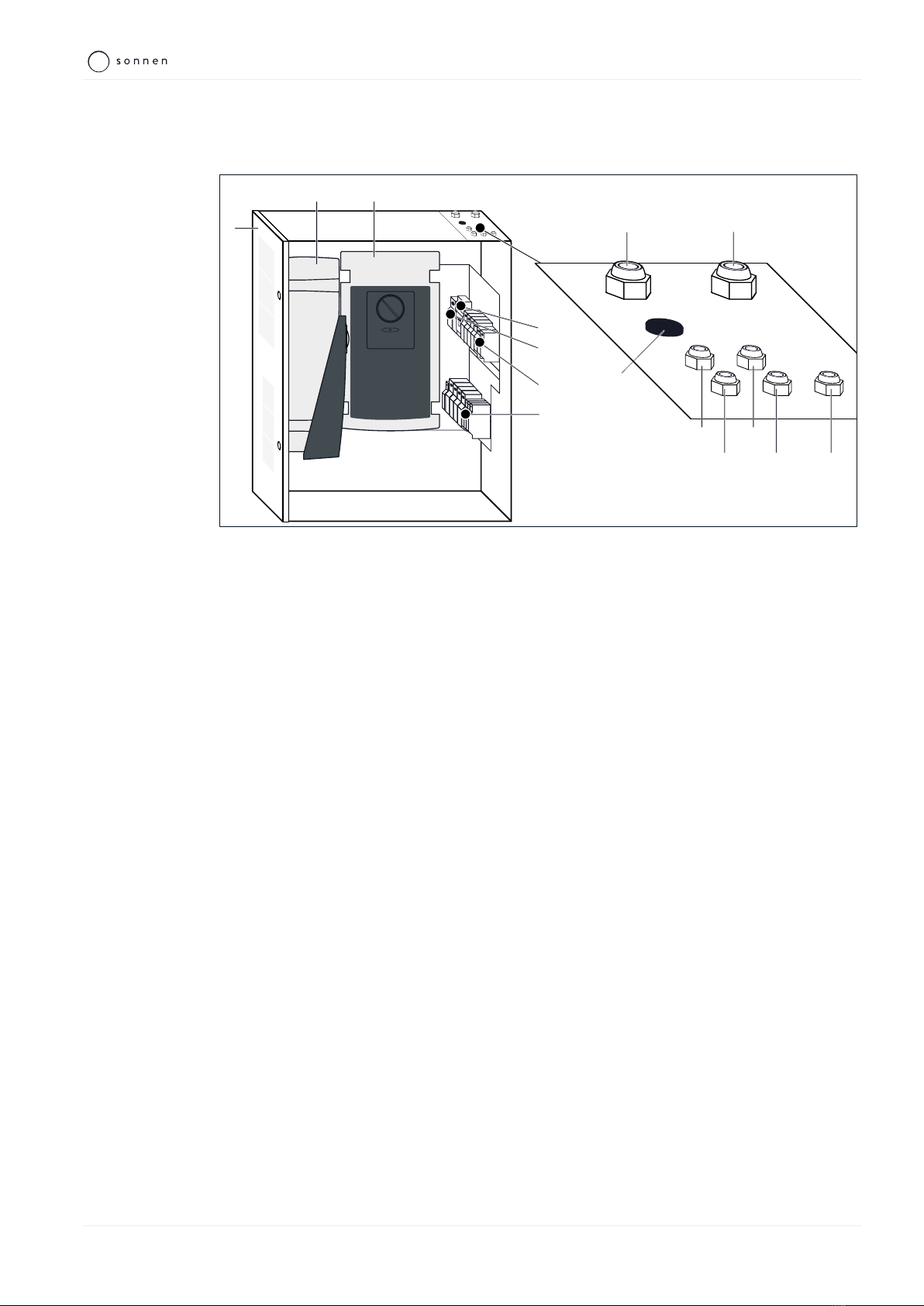
3.2.1 System components of the Backup-Box
4
7
6
8 9
10
13 14 15
1
32
5
11 12
Illustration1: System components of the Backup-Box
1 Backup-Box 5 X3.B terminal strip position
2 Slave inverter 6 X1.B terminal strip position
3 Master inverter 7 X2.B terminal strip position
4 F1.B Miniature Circuit Breaker
Cable glands
8 Mains IN 12 Minus (negative) battery cable
9 Mains OUT 13 Control signal cable
10 Cable for signalling contact 14 Earthing cable to storage system
11 Plus (positive) battery cable 15 Earthing cable to main earthing terminal

3 | Product description
10 / 40 Installation instructions sonnenBackup-Box
3.2.2 Inverters of the Backup-Box
NOTICE Incorrect switch position on the inverters
Damage to the inverters of the Backup-Box!
The correct switch position was marked by a label.
Do not change the switch position of the rotary switches on the two invert-
ers of the Backup-Box.
The two inverters within the Backup-Box each have a rotary switch and an LED light.
Rotary switch
It is essential for the function of the Backup-Box that the rotary switches on both inverters
are set correctly. The rotary switches have been factory set in the correct position and this
position has been marked by a sticker.
Do not change the switch position on the inverters.
• Master inverter: STANDBY area.
• Slave inverter: OFF.
LED light
The LED light indicates the current state of the inverter:
LED colour Status Meaning
-Off Power supply switched off
green Permanently illuminated Consumer device switched on
Blinking slowly Standby operation, no consumer device was recog-
nized
red Blinking slowly System error; please contact the sonnen Service
Blinking quickly Overcurrent
Permanently illuminated Overheating
red-green Blinking slowly Battery undervoltage or low charge state
Blinking quickly Battery overvoltage
Product description | 3
KD-492 | 22320 | EN | X02 11 / 40
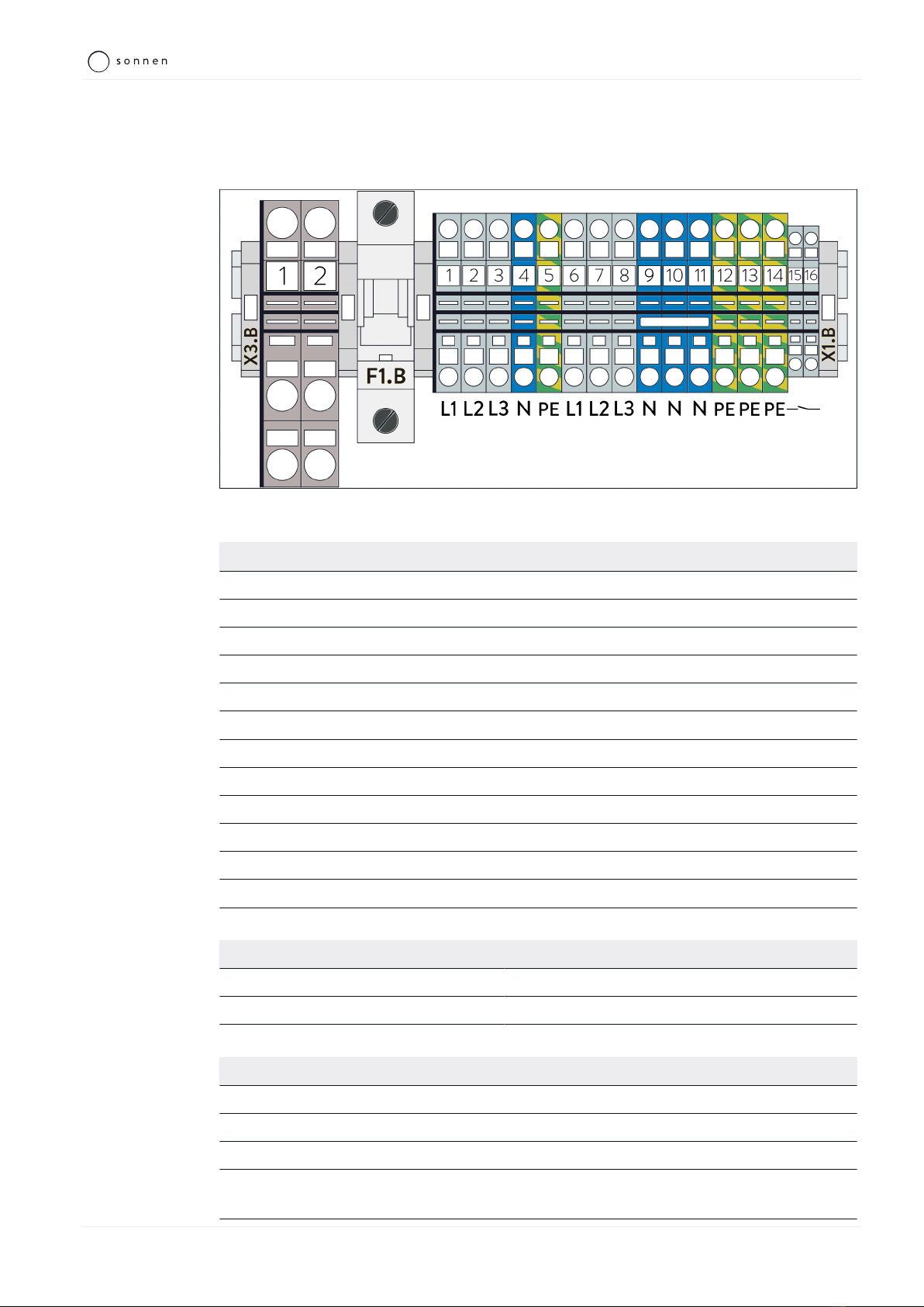
3.2.3 Connections on the Backup-Box
The positions of the terminal strips or terminals inside the Backup-Box can be found in sec-
tion System components of the Backup-Box [P.9].
Illustration2: Terminal strips X1.B and X3.B as well as Miniature circuit breaker F1.B
X1.B terminal strip overview
Terminal Function
1–3 AC line IN phase1–3
4 AC line IN neutral conductor
5 AC line IN earthing conductor
6–8 AC line OUT phase1–3
9 AC line OUT neutral conductor
10 AC line OUT neutral conductor – free
11 AC line OUT neutral conductor – free
12 AC line OUT earthing conductor
13 Earthing conductor to storage system
14 Earthing conductor to main earthing terminal
15 Potential-free signalling contact – closed in backup operation
16 Potential-free signalling contact – closed in backup operation
X3.B terminal strip overview
Terminal block Terminal Function
X3.B 1 Plus (positive) battery voltage
X3.B 2 Minus (negative) battery voltage
Control signal connection overview
Terminal strip:terminal Wire colour Function
X2.B:9 White GND (earth)
F3.B Brown Supply voltage 24 VDC
K5.B:A1 Yellow Digital output (DO) for emergency shutdown
K6.B:14 Green Digital input (DI) for grid detection (backup supply
active)
3 | Product description
12 / 40 Installation instructions sonnenBackup-Box
3.3 Type plate
The type plate is located on the outer surface of the Backup-Box. The type plate can be
used to uniquely identify the Backup-Box. The information on the type plate is required for
the safe use of the system and for service matters.
The following information is specified on the type plate:
• Item designation
• Item number
• Technical data
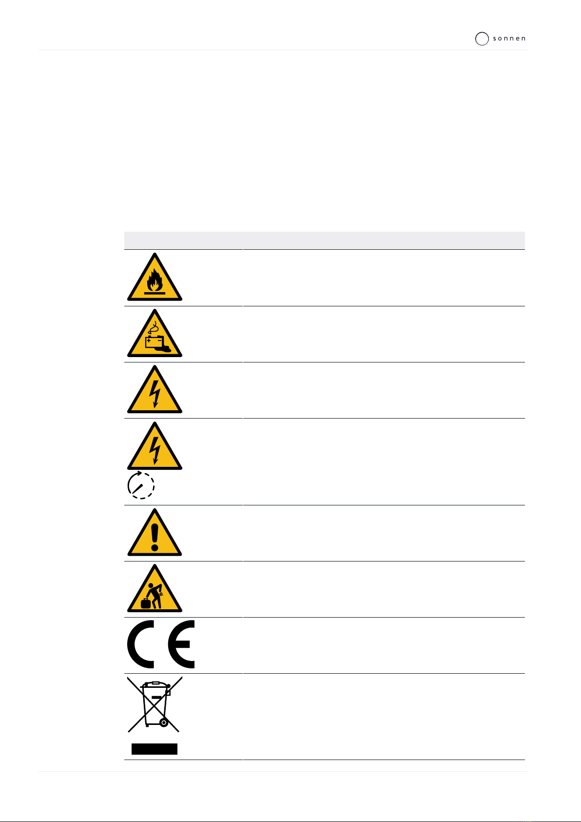
3.4 Symbols on the outside of the Backup-Box
Symbol Meaning
Warning: flammable materials.
Warning: hazards due to batteries.
Warning: electrical voltage.
5 min
Warning: electrical voltage. Wait five minutes after switching off (ca-
pacitor de-energising time).
Warning: The information in the manuals regarding the rotary switch
settings must be observed.
kg
Warning: product is heavy.
CE mark. The product meets the requirements of the applicable EU
Directives.
WEEE mark. The product must not be disposed of in household
waste, dispose of it through environmentally friendly collection
centres.

Product description | 3
KD-492 | 22320 | EN | X02 13 / 40
Symbol Meaning
Observe the documentation. The documentation contains safety in-
formation.
3.5 Storage and transport
Storage and transport conditions are defined in the product documentation of the storage
system.
Observe the same storage and transport conditions for the Backup-Box.
4 | Mounting
14 / 40 Installation instructions sonnenBackup-Box
4 Mounting
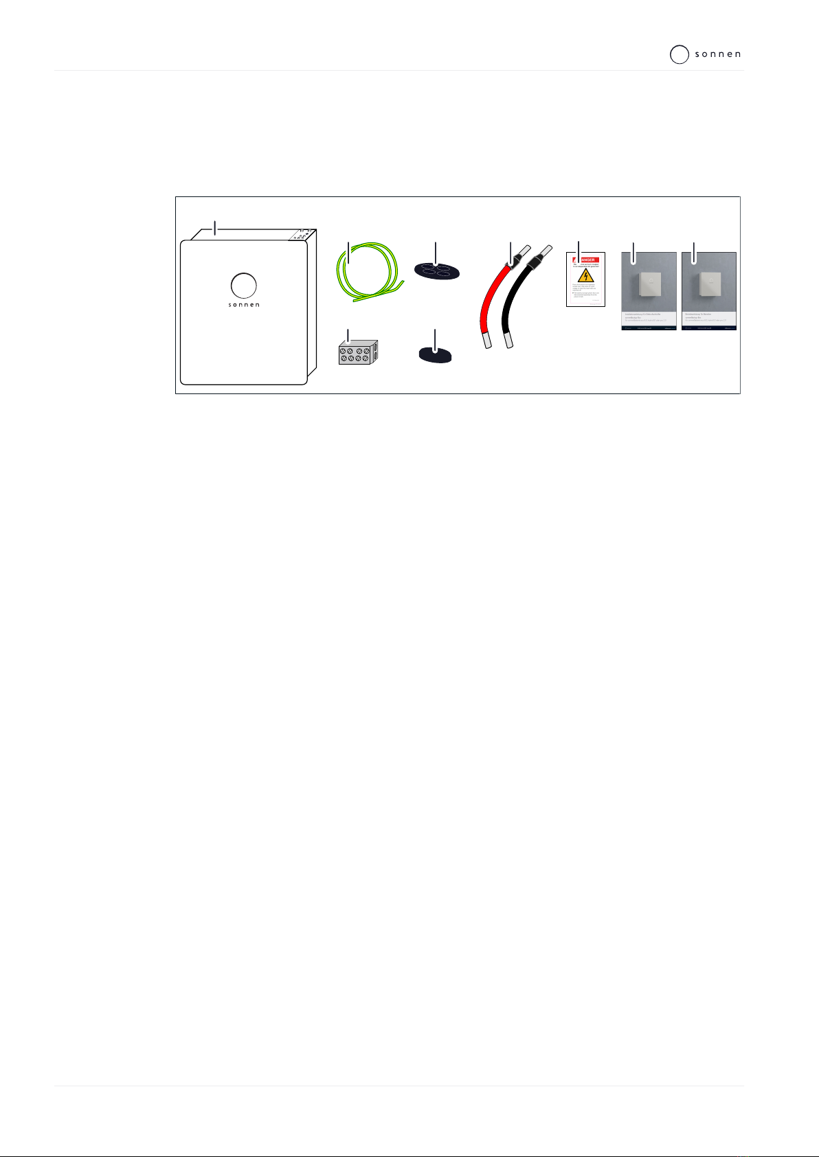
4.1 Scope of delivery
Check the following scope of delivery to ensure it is complete.
1x
1x
1
9
8
4
1x 1x
5
2x
7
1x
2
3
6
2x
1x
1x
1 Backup-Box incl. internally pre-assembled lines (Battery lines, Control signal line)
2 Earthing line for connection to the storage system
3 Branch terminal
4 Cable entry plate, round
5 Blanking plug with membrane grommet
6 Battery line, red and black
7 Safety label
8 Installation instructions
9 Operating instructions
4.2 Additional parts required
The following components are not included in delivery and must be selected and
ordered by the qualified electrician accordingly:
2 x mains connection cable (for Connecting the mains cables [P.24])
• Cable cross-section as per country-specific specification (at least 5G6mm²).
1 x earthing cable (for Connecting earthing cables [P.22])
• Cable cross-section: 10mm2.
Optional: Cable gland with multi-seal insert (see Routing cables into the storage system
[P.26]).
Mounting | 4
KD-492 | 22320 | EN | X02 15 / 40
4.3 Selecting the installation location
4.3.1 Requirements for the installation location
Observe the required ambient conditions (see Technical data [P.8]).
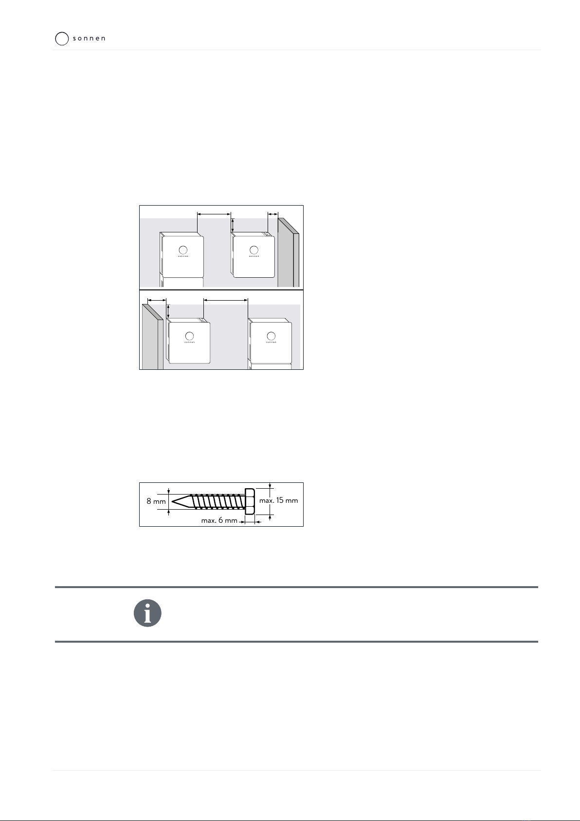
4.3.2 Observe minimum and maximum distances
• The Backup-Box should be mounted to the right or left of the storage system.
Install the Backup-Box at the same level as the top edge of the storage system, if pos-
sible.
15
5
10 - 50
15
10 30 - 50
Illustration3: Distances to the Backup-Box
(Figure not to scale - all specifications in centi-
metres)
Observe the specified maximum distances
between the Backup-Box and the storage sys-
tem, so that the length of the pre-assembled
and supplied cables is sufficient.
Observe the specified minimum distances to
the storage system and neighbouring objects,
so that there is sufficient heat dissipation, the
door can be opened easily and there is suffi-
cient space for installation and maintenance
work.
4.4 Mounting the Backup-Box
4.4.1 Requirements for mounting material
Use only screws with the following properties:
max. 6 mm
max. 15 mm
8 mm
Illustration4: Parameters of the screw used
• Screw head diameter: max. 15 mm
• Screw diameter: 8 mm
• Hight of screw head: max. 6 mm
• The screw lengths and the wall plugs used must be suitable for the nature of the wall.
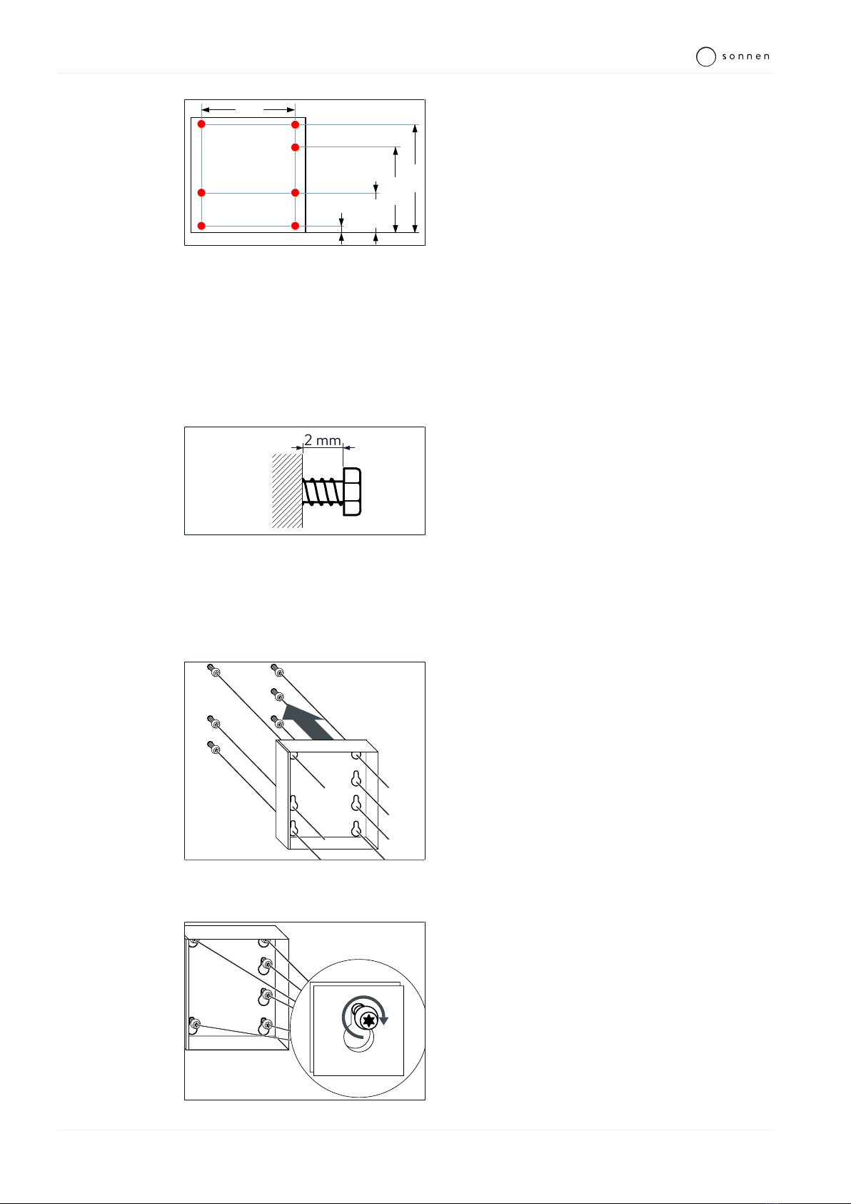
4.4.2 Drilling the holes
A drilling template is part of the packaging of the Backup-Box. Therewith it is
easier to mark the position of the holes on the wall. Please use the holes
marked as ‘base cabinet’ for the Backup-Box.
4 | Mounting
16 / 40 Installation instructions sonnenBackup-Box
1610
1532
838,5
524
226
33
626
526
Illustration5: Drill template for Backup-Box
(Figure not to scale - all specifications in milli-
metres)
Drill the holes shown in red in the illustration on
the left.
4.4.3 Fastening the Backup-Box
1. Apply the screws
There are keyhole attachments on the rear of the Backup-Box. The Backup-Box is mounted
using these attachments.
2 mm
Illustration6: Distance between screw head
and wall
Apply suitable screws and anchors (see Re-
quirements for mounting material [P.15]) to the
previously drilled holes.
The screw should not be completely screwed in. The screw head should protrude from the
wall by approx. 2 mm.
2. Attach the Backup-Box
Illustration7: Hanging up the Backup-Box
Attach the Backup-Box to the previously moun-
ted screws.
3. Tighten the screws
Illustration8: Tightening the screws
Tighten all visible screws.

Electrical installation | 5
KD-492 | 22320 | EN | X02 17 / 40
5 Electrical installation
DANGER Electrical work on the storage system and electrical distributor
Danger to life due to electrocution!
Switch off the storage system to electrically isolate it.
Disconnect the relevant electrical circuits.
Secure against anyone switching on the device again.
Wait five minutes so the capacitors can discharge.
Check that the device is disconnected from the power supply.
Only licensed electricians are permitted to carry out electrical work.
DANGER Touch voltage in the event of a fault during backup operation
Danger to life due to electrocution!
A residual current device (RCD) must be installed downstream of the output
of the Backup-Box.
NOTICE Observe maximum line lengths
None of the lines connected to the Backup-Box and the storage system
(mains line, ethernet line, other data lines) are allowed to exceed a maximum
length of 30m.
5 | Electrical installation
18 / 40 Installation instructions sonnenBackup-Box
5.1 Emergency operation design
Before installation, the installer must explain or clarify with the operator the following
points.
• Emergency operation does not offer the same output as grid operation.
• Three-phase current is not available during emergency operation (as only one phase is
supplied with power).
•Which consumers should be supplied with power in emergency operation? The current
paths in the building network can be installed in such a way that phase L1 of the Backup-
Box (emergency phase) is laid on the phase that supplies power to the relevant con-
sumers. The electrical consumers which are crucial for the operator in emergency oper-
ation are relevant here. Different consumers which may be important during a grid out-
age are specified in the sample calculation presented below.
•How much capacity of the storage system should be reserved as an emergency buffer?
The following example can be used to determine this. This example is based on a grid
outage lasting one hour (the individual power consumption values are estimated values).
Electrical consumer Power
consumption
[W]
Active during
grid outage
[h]
Electrical work
[kWh]
Refrigerator 600 0.25 0.15
Freezer 600 0.25 0.15
Heating 700 0.25 0.175
Door/garage door opener 50 0.1 0.005
Aquarium pump 20 1 0.02
Lighting 500 1 0.5
Router, telephone 10 1 0.01
Flat-screen television/radio 100 1 0.1
Alarm system, grid-connected smoke
detector
50 1 0.05
Total 1.16
In this example, the total power requirement for a grid outage lasting one hour is approx.
1.2kWh, in order to maintain the function of all of the listed consumers.
Use this calculation to determine with the operator which emergency buffer should be
set, taking the total capacity of the storage system and other requirements (e.g. from
sonnenFlat tariff) into account (see Setting the backup buffer [P.32]).

Electrical installation | 5
KD-492 | 22320 | EN | X02 19 / 40
5.2 Positioning components in the electrical distributor
The following components must be installed in the electrical distributor for the Backup-
Box:
•Circuit breaker (miniature) | typeC | 32A
A miniature circuit breaker with typeC tripping characteristics and a nominal current of
32A must be installed upstream of the input for the Backup-Box.
•Residual current device (RCD)
A residual current device must be installed at the output of the Backup-Box. This RCD pro-
tects against electrocution during backup operation. An RCD must be used which complies
with the respective country-specific regulations and the local network conditions.
•In network with TT earthing: Additional residual current device (RCD) | 300mA
In networks with TT earthing, an additional residual current device must be installed up-
stream of the input for the Backup-Box. An RCD with a nominal differential current of
300mA is sufficient for this. RCDs with a nominal differential current of 100mA or 30mA
can also be used. A selective residual current device must be used.
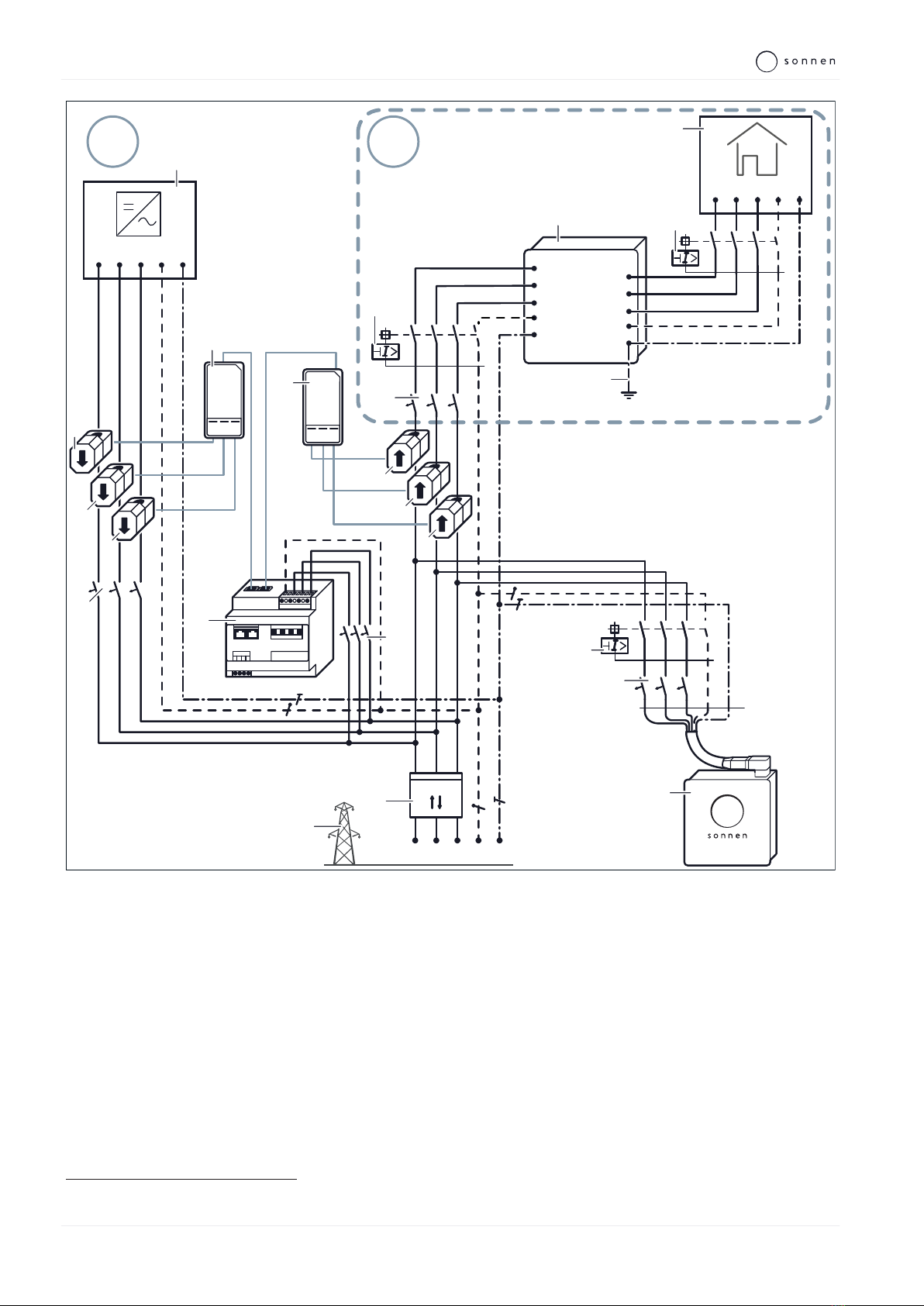
5.3 Wiring components in the electrical distributor
Wire the components previously installed in the electrical distributor as shown in the
following figure.
Note:
The figure on the following page shows a connection diagram with an overview of the elec-
trical connections of a storage system with the Backup-Box. Two areas A and B are labelled
in the figure.
• The figure shows the installation of a sonnenBatterie eco8.0 as an example, which has
been installed in accordance with the specifications in the product documentation
(areaA) and to which a Backup-Box has now been added (areaB).
• In the case of a sonnenBatterie hybrid8.1, pro2.0 or a sonnenFlat, the installation of
the Backup-Box (areaB) is identical, but the installation of the storage system itself in
areaA differs.
The information on the differing electrical installations can be found in the documentation
for the product in question.
5 | Electrical installation
20 / 40 Installation instructions sonnenBackup-Box
AB
11
L1 L2 L3 N PE
10
12
1
2
5
kWh 3~
L1 L2 L3 N PE
NL1 L2 L3
A1 A2
16
15
13
14
3
1
2
L1 L2 L3 N PE
L1 L2 L3 N PE
17
1
1 2 3
2
6
1
4
9
8
7
L1
L2
L3
N
PE
L1
L2
L3
N
PE
6
3
2
33
4
1 2 3
5
Section A - Existing installation of the storage system
1 PV inverter 7 Current transformer consumption L1 13 Bidirectional counter
2 Current transformer generation L1 8 Current transformer consumption L2 14 Public electrical mains
3 Current transformer generation L2 9 Current transformer consumption L3 15 Power meter MCB
4 Current transformer generation L3 10 RCD1
5 Transformer interface generation (A1) 11 Storage system MCB216 Power meter
6 Transformer interface consumption (A2) 12 Storage system 17 PV inverter MCB
Section B - Altered installation by Backup-Box
1 Consumers in building 3 Earth connection 5 RCD (in TT networks)
2 RCD 4 Backup-Box 6 Miniature circuit breaker | Type C | 32A
1 According to the requirement in the installation instructions of the storage system.
2 Miniature Circuit Breaker.
Table of contents
Other Sonnen UPS manuals


