Microcare 1kW24V User manual
0
1Kw24V UPS Manual

1
Contents
1. INTRODUCTION .......................................... 2
2. SAFETY INSTRUCTION .............................. 2
3. SYSTEM DESCRIPTION ............................. 3
4. UPS OPERATION ........................................ 4
5. UPS PROGRAMMING ................................. 9
5. FAULT TROUBLE SHOOTING .................. 18

2
1. INTRODUCTION
1.1 General Description
i. When the Eskom power is flowing through the UPS it keeps the voltage at a constant
220volts not allowing fluctuations in the Eskom power to affect the ATM.
ii. When loa she ing occurs the UPS seamlessly shifts across to battery power keeping the
ATM operational for a certain time frame. (loa epen ent)
iii. The battery system is a 24volt system.
iv. Due to the batteries not being eep cycle batteries the software on the ATM shuts the UPS
own at 20volts. This equates to at least 90% of the power generate by the batteries.
v. Once the batteries have shut own the UPS goes into a stan by mo e. This allows the UPS
to save the remaining voltage in the batteries.
vi. Once Eskom returns the UPS automatically starts up an commences in the powering up of
the ATM.
vii. The batteries shoul thus never be allowe to ischarge completely.
1.2 Key Features
1. Compatible with both linear an non-linear loa .
2. 24 hours operation on the UPS.
3. DC start an automatic self- iagnostic function.
4. High Power 3 stage Charger
5. High efficiency esign to save electricity.
6. Low heat issipation in long time operation.
7. Design to operate un er harsh environment.
1.3 Important Notices
• Rea instructions carefully before operating Inverter.
• Inverter connection instructions must be followe .
• The unit shoul only be opene by skille personal.
• Retain the loa within in the rating of the UPSr to prevent Overloa /Short Circuit.
• Keep The UPS Clean & Dry.
2. SAFETY INSTRUCTION
2.1 Positioning
1. Do not put the Inverter on rugge or incline surface.
2. Do not install the UPS near water or in amp environments.
3. Do not block off ventilation openings in the UPS housing an on’t leave objects on
top of the UPS.
4. Keep the UPS far away from heat emitting sources.
5. Do not expose it to corrosive gas.
6. Ambient temperature: 0˚C - 40˚C.
2.2 Maintenance and Service
1. Caution – Risk of Electric Shock.
2. Batteries may cause electric shock an have a high short-circuit current. Please
take the precautionary measures specifie below an any other measures
necessary when working with batteries.
• Remove wristwatches, rings an other metal objects.
• Use only tools with insulate grips an han les.

3
3. SYSTEM DESCRIPTION
3.1 System Description.
3.1.1 System Front View.
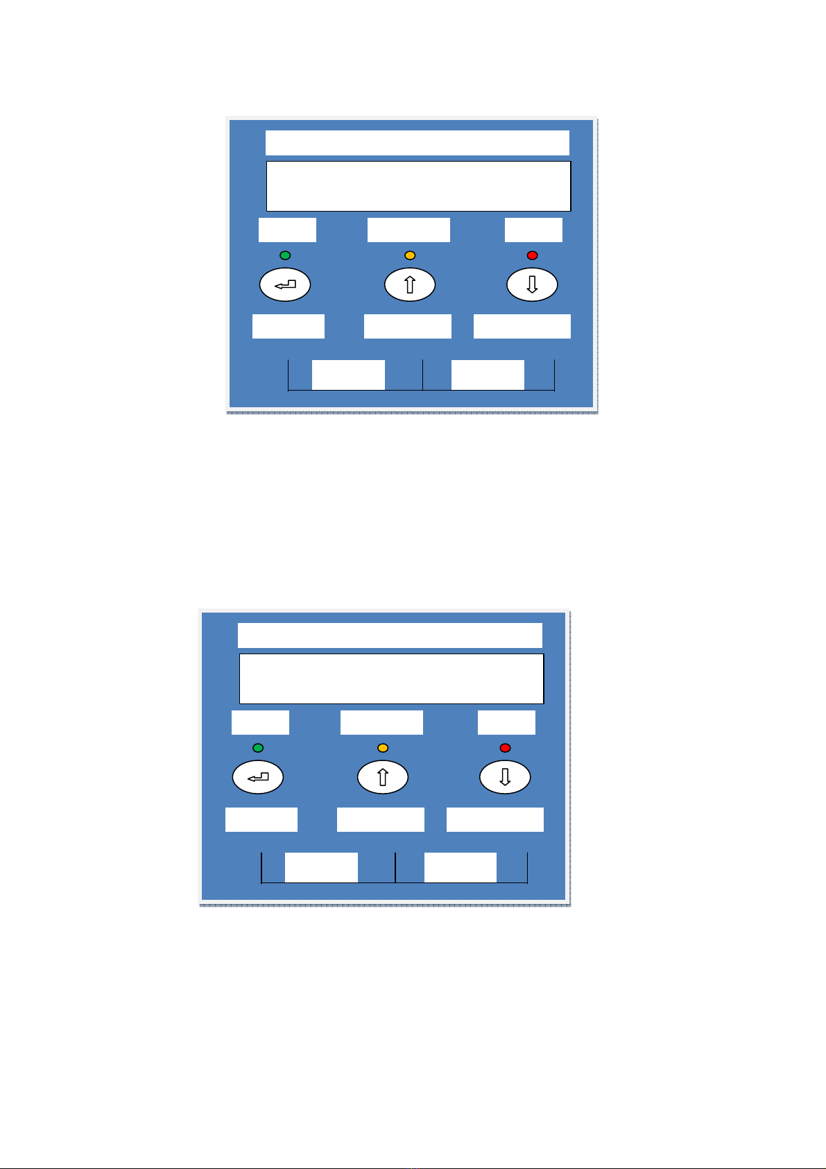
3.2 Front Panel Description or LCD Model.
3.2.1 LCD Display: This in icates the UPS’s operational information, inclu ing output
voltage, battery voltage, output loa an insi e temperature.
3.2.2 UP–Key: Use to move the isplay up.
3.2.3 DOWN–Key: Use to move the isplay own.
3.2.4 ENTER–Key: It is presse with the UP–Key to turn on the UPS. Push the ENTER
button to confirm or store DATA.
3.2.5 Push the UP an DOWN keys together to turn off the inverter.
3.2.6 Fault LED (Re ): To in icate the UPS is in a fault con ition because of UPS
shut own; overloa or over temperature.
3.2.7 Warning LED (Yellow): To in icate the UPS is Using Battery Power & Not Mains
Power.
3.2.8 Normal LED (Green): To in icate the INVERTER is operating normally.

4
4. UPS OPERATION
4.1. Operation Procedure or the UPS.
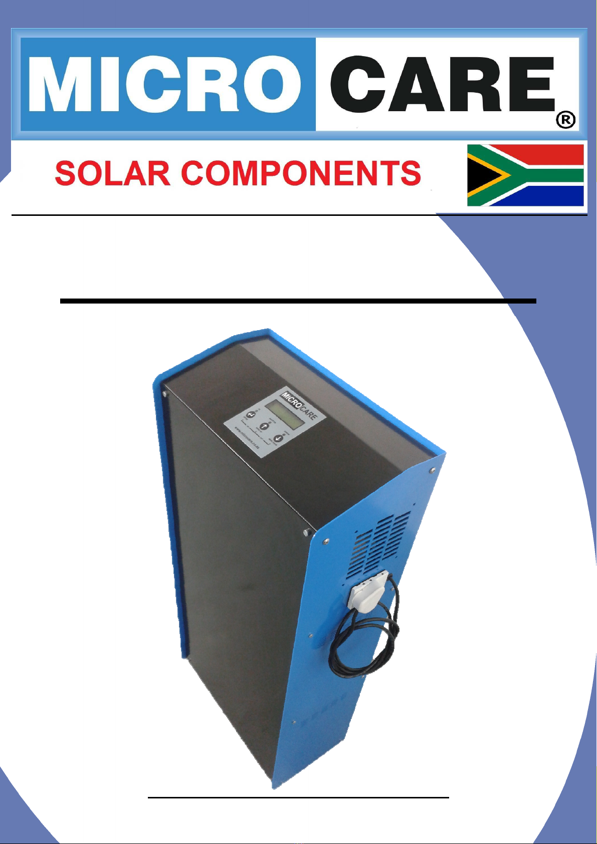
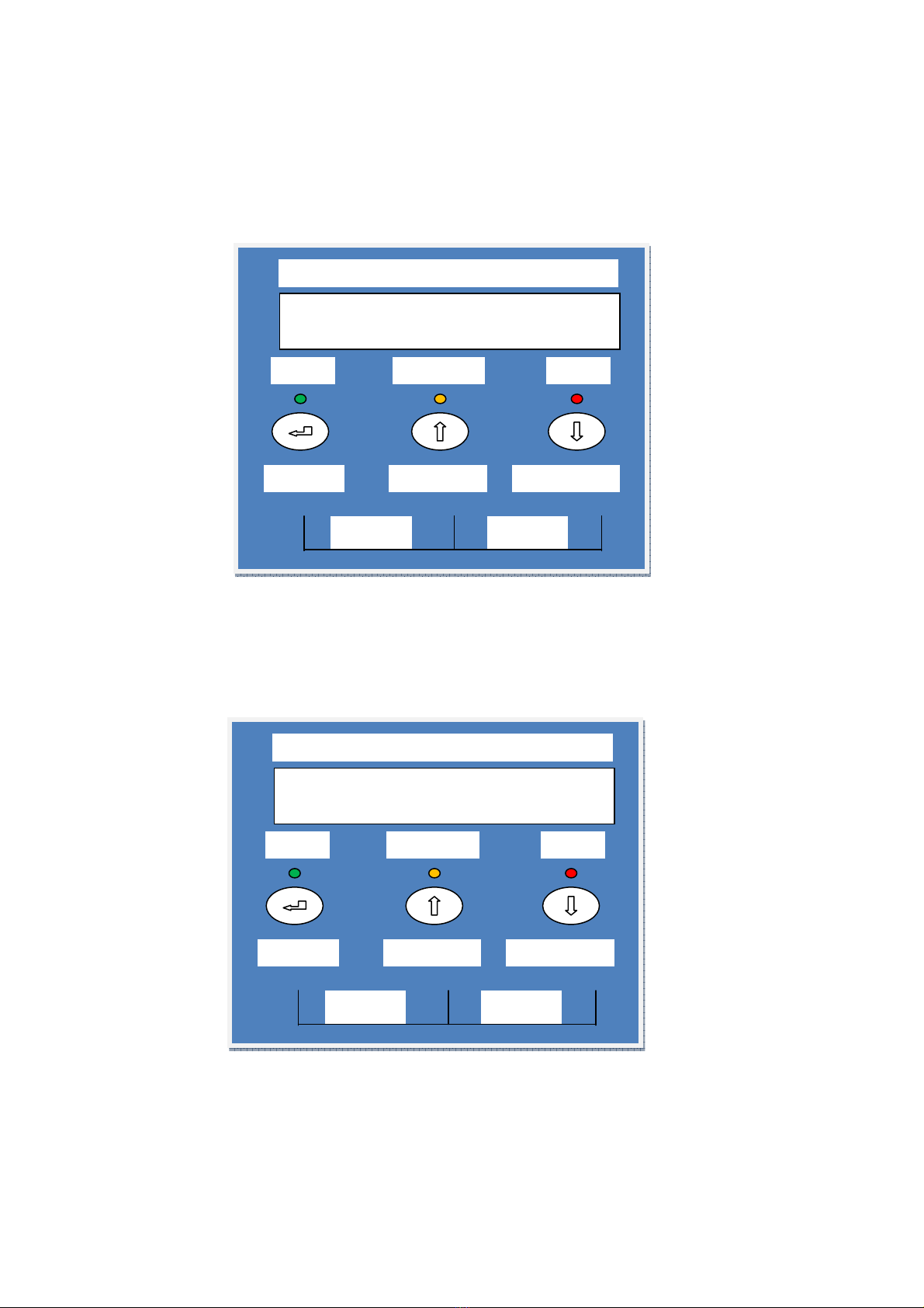
Turn on the Circuit Breaker on the UPS.
The isplay then changes to:
The isplay then changes to:
UPS TURNED OFF
…CALIBRATING…
MICROCARE
ON OFF
ENTER
Menu Down
Menu Up
OK
Inverter
Error
MI
CROCARE
1
KW
OUTPUT
=
LOW
MICROCARE
ON OFF
ENTER
Menu Down
Menu Up
OK
Inverter
Error
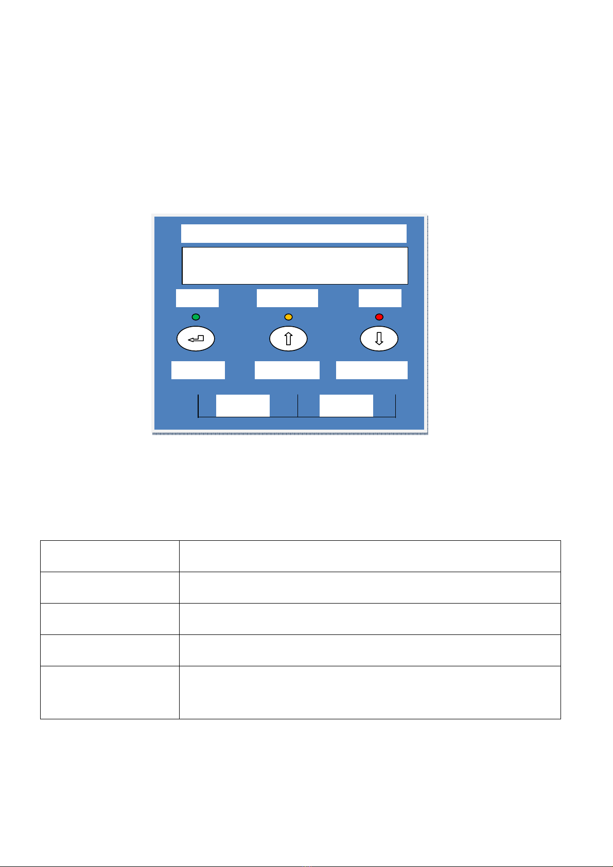
MICROCARE
UPS
…PLEASE WAIT…
MICROCARE
ON OFF
ENTER
Menu Down
Menu Up
OK
Inverter
Error

5
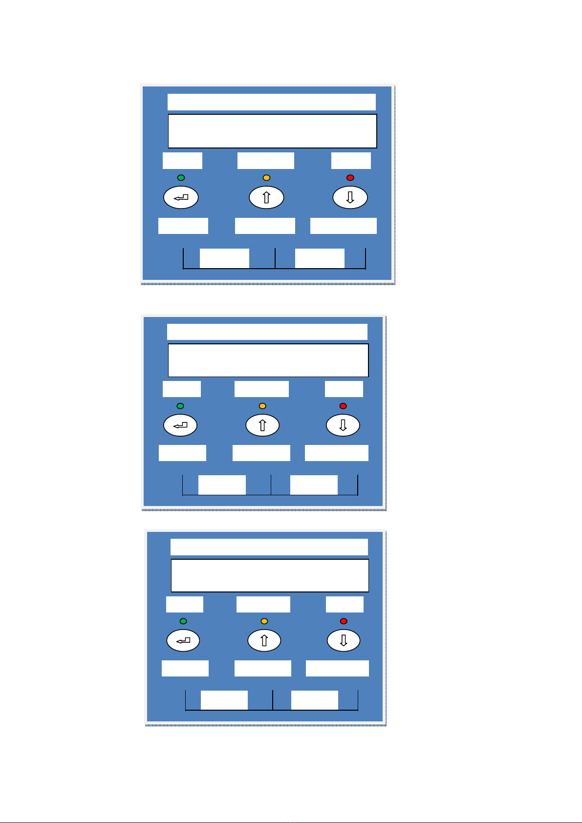
The isplay then changes to:
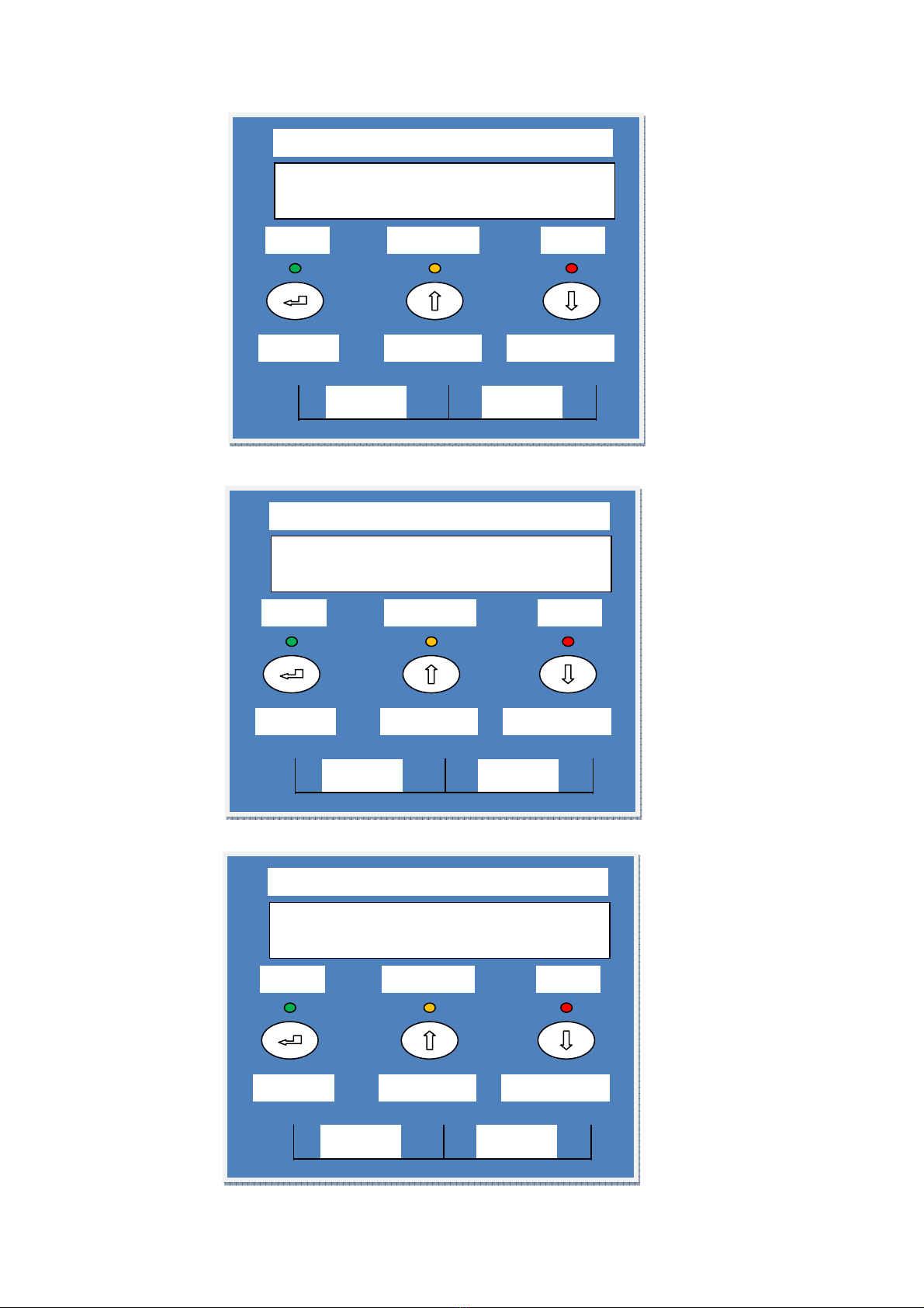
By pressing the Enter-key an the UP-key simultaneously for 3 secon s, the UPS will start up
an the OK LED lights up to in icate the power is from the inverter to the loa .
The isplay will show:
By turning on a loa the OUTPUT LOW will change to in icate the amount of LOAD as a % of
the UPS unit being use in KW.
When the Up-key an the Down-Key are presse simultaneously for 3 secon s, the UPS will be
turne Off.
LCD DISPLAY MENU
With the inverter in the ON position use the Up/Down keys to select menu- isplays of the LCD
escribe below.
M
ICROCARE
1
KW
OUTPUT
=
LOW
MICROCARE
ON OFF
ENTER
Menu Down
Menu Up
OK
Inverter
Error
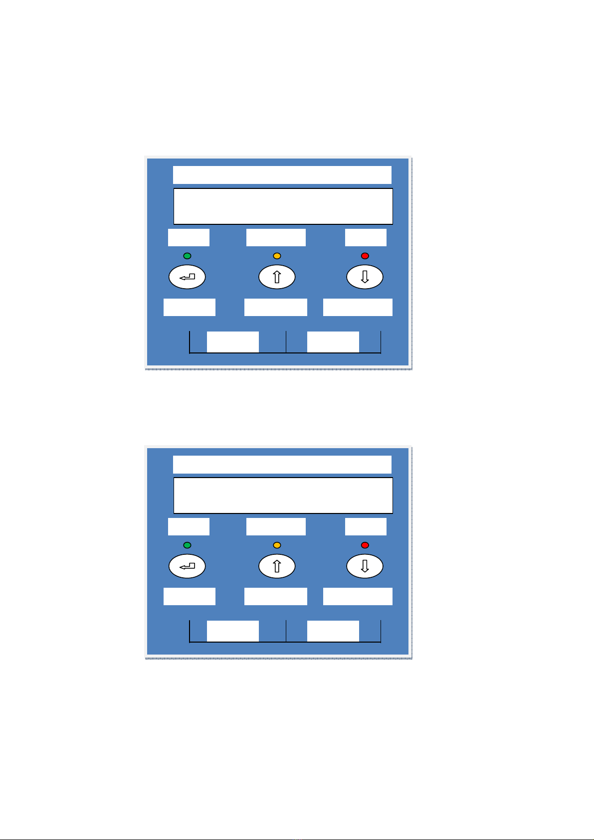
UPS TURNED OFF
MICROCARE
ON OFF
ENTER
Menu Down
Menu Up
OK
Inverter
Error
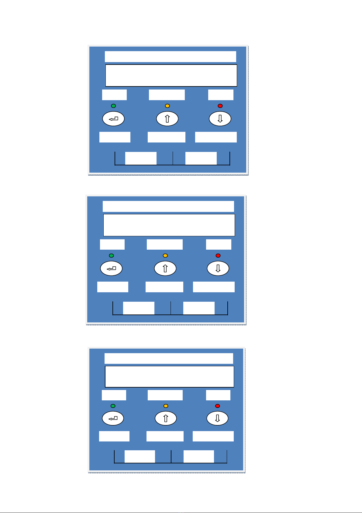
Using the UP/Down Buttons the following screens can be seen.
This shows the power rating of the UPS an its % output.
Using the UP arrows the following etails can be checke :
This shows the battery voltage an the amps that the UPS is rawing from the battery.
If the battery Amps changes to CHR AMPS
This shows the Charge Amps that are being put back into the battery bank from the
charging source.
M
ICROCARE
1
KW
OUTPUT
=
2
0%
MICROCARE
ON
OFF
ENTER
Menu Down
Menu Up
OK
Inverter
Error
BATT VOL
T
:
2
4.2
BATT AMPS
:
7.0
MICROCARE
ON
OFF
ENTER
Menu Down
Menu Up
OK
Inverter
Error
B
ATT VOLT
:
2
4.7
CHR AMPS
:
10.0
MICROCARE
ON
OFF
ENTER
Menu
Menu Up
OK
Inverter
Error
7
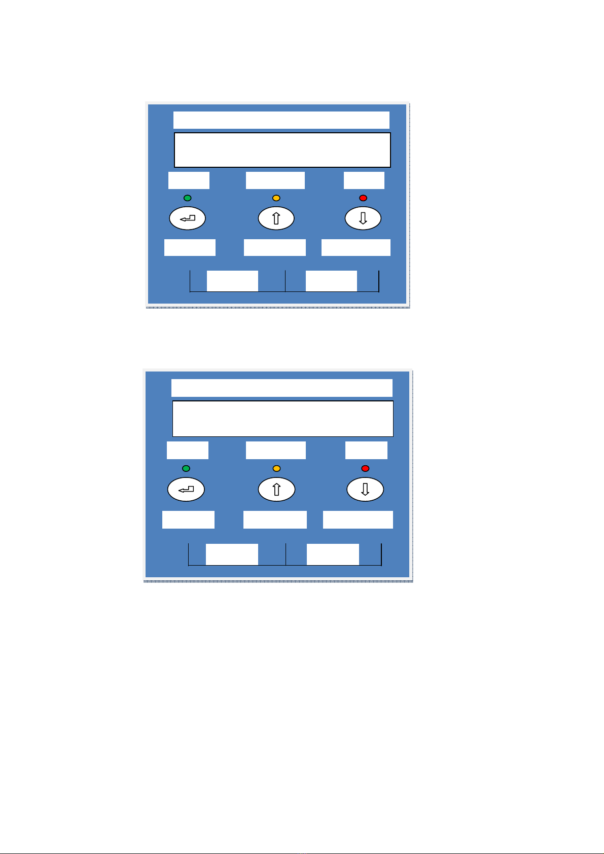
This shows the output voltage an amps that the loa is rawing from the Inverter
supplie Power.
Shows the Gri Volts an power raw from the gri power supply:
This shows the internal temperature of the UPS.
TEMPE
RATURE
COOL
MICROCARE
ON OFF
ENTER
Menu Down
Menu U
p
OK
Inverter
Error
U
PS VOLTS
:
22
2
UPS AMPS : 7.0
MICROCARE
ON OFF
ENTER
Menu Down
Menu Up
OK
Inverter
Error
GRID VOLTS
:
227
GRID AMPS : 10.0
MICROCARE
ON OFF
ENTER
Menu Down
Menu Up
OK
Inverter
Error
8
This shows that the control car s in the UPS have a 100% communication level.
This in icates the serial number of the Inverter.
The Serial number of the inverter needs to be noted and supplied when requesting
any fault support information.
SERIAL NUMBER:
MCxx007
MICROCARE
ON OFF
ENTER
Menu Down
Menu Up
OK
Inverter
Error
SIGNAL STRENGTH
DISPLAY
-
UPS
100%
MICROCARE
ON
OFF
ENTER
Menu Down
Menu Up
OK
Inverter
Error
9
5. UPS PROGRAMMING
There are two MENUS’ which allow the user to change either the SET UP or the BATTERY
menus.
Push the UP / DOWN keys to select which menu is to be change .
Push ENTER if you want to change the set up menu.
By pushing ENTER button you can change whether the inverter runs in NORMAL SENSE
mo e; or SOLAR CONTROL mo e.
NORMAL SENSE is to be selecte whenever using a UPS Unit.
ENTER
SETUP MENU ?
MICROCARE
ON OFF
ENTER
Menu Down
Menu Up
OK
Inverter
Error
UPS
MODE
NORMAL SENSE
MICROCARE
ON OFF
ENTER
Menu Down
Menu Up
OK
Inverter
Error

10
Push the ENTER button. The menu changes to:
SOLAR CONTROL Mo e is not to be use on the UPS Unit.
To change the menu, push the UP button.
The menu will then change to:
The Settings available for this are as follows:
3mS NO
SOFTSTART
3 milli secon transfer time an will restart loa instantly -
with mains fail pre iction.
5mS NO
SOFTSTART
5 milli secon transfer time an will restart loa instantly -
with mains fail pre iction.
8mS +
SOFTSTART
(Default) 8 milli secon transfer time an will ramp the
RMS voltage up in less than 1 secon - with mains fail
pre iction.
GEN +
SOFTSTART
8 milli secon transfer time an will ramp the RMS voltage
up in less than 1 secon - with no mains fail pre iction.
GEN + SLOW
RAMP
8 milli secon transfer time an will ramp the RMS voltage
up in 3 secon s - with no mains fail pre iction.
UPS
MODE
SOLAR CONTROL
MICROCARE
ON OFF
ENTER
Menu Down
Me
nu Up
OK
Inverter
Error
TRANSFER
SWITCH
8mS + SOFTSTART
MICROCARE
ON OFF
ENTER
Menu Down
Menu Up
OK
Inverter
Error
11
To change the menu, push the UP button.
The menu will then change to:
The sensitivity of the SHORT CIRCUIT TRIP may be change through 5 LEVELS. Push
ENTER to select the mo e:
HIGH NO RESET High sensitivity to short circuits - will trip the inverter after a short
elay time perio .
MED NO RESET Me ium sensitivity to short circuits - will trip the inverter after a
me ium elay time perio .
HIGH 3x RESET High sensitivity to short circuits - will trip the inverter after a short
elay time perio , with soft start to prevent in rush current.
MED 3x RESET Me ium sensitivity to short circuits - will trip the inverter after a short
elay time perio , with soft start to prevent in rush current.
LOW EMERGENCY Low sensitivity to short circuits - will trip the inverter after a long
elay time perio . Only to Used in Emergency Situations.
LOAD
MONITORING
HIGH NO RESET
MICROCARE
ON OFF
ENTER
Menu Down
Menu Up
OK
Inverter
Error

12
To change the menu, push the UP button, The menu will then change to:
The settings available are as follows:
AC OUTPUT = NOR - This will allow the inverter to supply rate power.
A 5Kw Inverter will supply 5kw of Power.
AC OUTPUT = 200% - This will allow the inverter to supply 200% rate power.
A 5Kw Inverter will supply 10kw of Power.
If the grid fails and the load is exceeding 100% of
the inverter power, the inverter will shut down due
to overload.
To change the menu, push the UP button, The menu will then change to:
The settings available are as follows:
NO DELAY As soon as Gri power is available the Inverter will synchronise an
switch from battery to Gri .
DELAY = 30Sec 30 secon s after Gri power is available the Inverter will
synchronise an switch from battery to Gri .
DELAY = 5 Min 5 minutes after Gri power is available the Inverter will synchronise
an switch from battery to Gri .
It woul be a goo i ea to select a 30 secon s or 5 minute elay after loa she ing to allow the
gri power to stabilise.
IF AC I
NPUT
=
ON
AC OUTPUT = NOR
MICROCARE
ON OFF
ENTER
Menu Down
Menu Up
OK
Inverter
Error
LOAD
TRANSFER
NO DELAY
MICROCARE
ON OFF
ENTER
Menu Down
Menu Up
OK
Inverter
Error
13
Pushing the UP button will give you 3 options to SAVE the change ata. The isplay will show:
EXIT, DO NOT SAVE
SET UP MENU ?
MICROCARE
ON OFF
ENTER
Menu Down
Menu Up
OK
Inverter
Error
RESTORE FACTORY
SET UP MENU ?
MICROCARE
ON OFF
ENTER
Menu Down
Menu Up
OK
Inverter
Error
EXIT AND SAVE
SET UP MENU ?
MICROCARE
ON OFF
ENTER
Menu Down
Menu Up
OK
Inverter
Error
14
If the changes to the settings nee to be save push ENTER if the enter button is pushe for any
of the above then the unit will show:
If no entry is ma e for 1 minute the isplay will return to the main menu.
Use the UP/DOWN button to select BATTERY menu:
Push ENTER to access the Battery Setup Menu:
SAVING DATA TO
INTERNAL MENU
MICROCARE
ON OFF
ENTER
Menu Down
Menu Up
OK
Inverter
Error
ENTER
BATTERY MENU ?
MICROCARE
ON OFF
ENTER
Menu Down
Menu Up
OK
Inverter
Error

15
To change the BATTERY CHARGE menu push ENTER button:
The Settings available for this function are as follows:
50% OF RATED CHR - (Default). 50% of charge rate as per list supplie below.
75% OF RATED CHR - 75% of charge rate as per the list supplie below.
MAX CHARGE RATE - 100% of charge rate as per the list supplie below.
TURNED OFF - 0% of charge rate as per the list supplie below.
SLOW CHARGE - 5% of charge rate as per the list supplie below.
25% OF RATED CHR - 25% of charge rate as per the list supplie below.
INVERTER CHARGE AMPS
1Kw24V 30A
In regar s to the battery charge level – The Level selecte will allow the battery charge to
the batteries.
25% OF RATED CHR – On a 1Kw24V Inverter will allow a charge of 7.5A to the battery.
75% OF RATED CHR – On a 1Kw24V Inverter will allow a charge of 22.5A to the battery.
To change the menu, push the UP button, The menu will then change to:
This setting is not to be a juste on the UPS Units.
AC
INPUT
POWER
LEVEL (X) SELECTED
MICROCARE
ON OFF
ENTER
Menu Down
Menu Up
OK
Inverter
Error
BATTERY
CHARGE
LEVEL (X) SELECTED
MICROCARE
ON OFF
ENTER
Menu Down
Menu Up
OK
Inverter
Error

1
To change the menu, push the UP button.
The menu will then change to:
By pushing ENTER this allows the user to a just the BATTERY BOOST voltage.
To change the menu, push the UP button.
The menu will then change to:
This allows the user to select the TIME that the BOOST VOLTAGE will be hel at before
changing to FLOAT. By pushing ENTER you can select 1, 2 or 3 hours.
BATTERY
BST
TIME
BST FOR 2 HOURS
MICROCARE
ON OFF
ENTER
Menu Down
Menu Up
OK
Inverter
Error
BATTERY
BOOST
BST = 29.2 volts
MICROCARE
ON OFF
ENTER
Menu Down
Menu Up
OK
Inverter
Error
17
To change the menu, push the UP button.
The menu will then change to:
This selects at what BATTERY LOW VOLTAGE the UPS will shut own. By pushing
ENTER you can select to change the voltage.
Push the UP button.
It is possible to FORCE the charger to go into another charge mo e on a temporary basis.
If the charger is in FLOAT but you require it to go back into BOOST then the next menu
will allow this.
Pushing the ENTER button allows the charge to be change from AUTO to BOOST or
FLOAT.
Push the UP button:
This will give you the options of saving the changes that have been ma e. Push ENTER at
the correct SAVE menu.
BATTE
RY
LOW
OFF AT 22.0 VOLTS
MICROCARE
ON OFF
ENTER
Menu Down
Menu Up
OK
Inverter
Error
FORCE
BAT
INTO
AUTO CHARGE
MICROCARE
ON OFF
ENTER
Menu Down
Menu Up
OK
Inverter
Error

18
5. FAULT TROUBLE SHOOTING
1. If the UPS is not operational after Eskom has come back on after load shedding then it could
be one of three scenario’s:
a. The Eskom power has been off an e tended period and the batteries have gone flat due to
the fact that even in standby mode the UPS will still be drawing a charge from the batteries.
b. The UPS is in need of a software upgrade to correct the fault
c. There is a fault with the batteries.
If the system is non operational (no lights are on) once the custodian enters the cubicle the
following steps need to be completed:
1) Ensure the breaker on the side of the unit is turned down.
2) Check that all the LCD display lights are off.
3) Ensure that the UPS is plugged into Eskom and the Eskom power to the UPS is off.
4) Turn the ATM off if it is still on.
5) Plug the ATM and V-Sat into Eskom and power up to ensure no fault with the ATM.
6) Power down the ATM if there is no fault.
7) Re-connect the ATM and V-Sat into the adaptor supplied which is connected to the UPS.
8) Flip the breaker on the side of the UPS into the up position.
9) The unit will turn on using the batteries.
10) The UPS LCD display should state “Please wait….”
11) The LCD display then states “UPS Turned Off …. Calibrating”
12) The LCD display then states “UPS Turned Off”
13) Then depress the center button (green) and left button (yellow) for 3 seconds.
14) The LCD Display will then state “UPS Turned On”
15) Once this phase is completed the UPS should be in operational mode.
16) Power up the ATM without turning on Eskom.
17) Once the ATM is on turn the Eskom plug that is connected to the UPS on.
18) The yellow light should after 3 seconds go out and the green light should come on. This
indicates that the UPS is running on mains power.
After 5 minutes when both the ATM and the UPS are operational follow this procedure:
1) Switch the Eskom plug that is connected to the UPS off.
2) After 3 seconds the green light will go out and the yellow light will come on. This implicates
that the UPS is running on batteries.
3) Ensure that the power supply to the ATM has not been disengaged and that it is operating
normally.
4) Wait for 2 minutes then switch the Eskom plug to the UPS back on.
5) After 3 – 5 seconds the yellow light will go off and the green light will come back on.
The unit has been tested if only briefly that it will switch from Eskom to the batteries should a
power failure occur. The unit should now be fully operational.

19
1) When the LCD Display registers a “Short Circuit” a number of faults could have occurred,
namely:
a) A greater than normal spike through the Eskom plug that shorts the fuse,
b) A short on the battery terminals or bad connection,
c) A possible short on the PCB cards inside the UPS due to dust, bugs, leaking water,
lightning strike,
d) The power output of the UPS has e ceeded the 1kw limit possible in the case of the UPS
being connected to 2 ATM’s or
e) The ATM has a built in 700 watt UPS that initializes once the ATM has been turned on.
2) When the “Short Circuit” occurs please follow the ne t instructions;
a) Ensure that the UPS is switched off in accordance with the procedure as listed above.
b) Once the unit is off check the fuse holder on the side of the UPS. It is easily unscrewed.
Should the fuse be blown please call a technician and report the fault. If the fuse keeps
blowing once changed a short circuit is materializing on the PC Boards. Please log a fault
report.
c) If the fuse is not blown, please check that the ATM does not have a built in UPS system.
Should there be an internal UPS System pull out the sliding tray that it rests on. There is a
green light on the right front of the UPS. Depress this button for 3 seconds until the internal
UPS turns off. Once this has been done check the back of the UPS for 2 power cables. One
is black the other should be white. One is male and the other a female connection. In order
to bypass this unit please unplug them both and reconnect them together. The internal UPS
is now disconnected. Please follow the re-connection procedure listed above.
d) If the ATM has any liquid damage or lightning strikes please log a fault report.
e) Should the UPS still remain non-operational once the power has been re-connected please
log a fault report.
f) Should the UPS continue to stay in Short Circuit Mode please disconnect the UPS from the
Eskom mains and plug the ATM and V-Sat into Eskom. Please log a fault report.
3) Should the UPS at any time register an “Internal Error” please log a fault report immediately?
This fault only registers once the internal software of the unit has been compromised due to
the faults listed above and needs to be rectified immediately.
4) Should the unit be completely non-operational ie, all the lights are off and it seems no power is
getting through the UPS to the ATM. Turn the UPS off at the Eskom socket. Re-connect ATM
and V-Sat back into Eskom socket and power up. Please log a fault report immediately. This
fault could be due to the batteries having run flat due to:
a) A malfunction within the UPS software allowing the batteries to deplete
b) A short that has compromised the charging software
c) A lightning strike that has compromised the charging software or
d) Faulty batteries
5)
Should there be a fault with the UPS please do not disconnect Eskom from the
unit or switch it off until a technician has contacted you.
Please merely plug the
ATM and V-Sat back into Eskom until we contact you to discuss the fault.
6) Please keep in mind that when the UPS is powering up 2 ATM’s the uptime during load
shedding is diminished by half. This is obviously load dependent.
COMMS ERROR:
1) Loose Ribbon Cables inside the UPS.
2) Ribbon Cables need to be pushed into the seating inside the UPS Correctly.
Trouble-shooting ( Red Light will be on)
Other manuals for 1kW24V
1
Table of contents
Other Microcare UPS manuals


