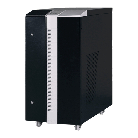
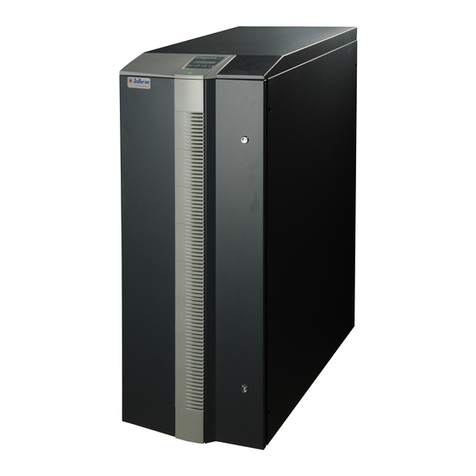
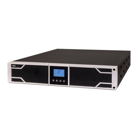
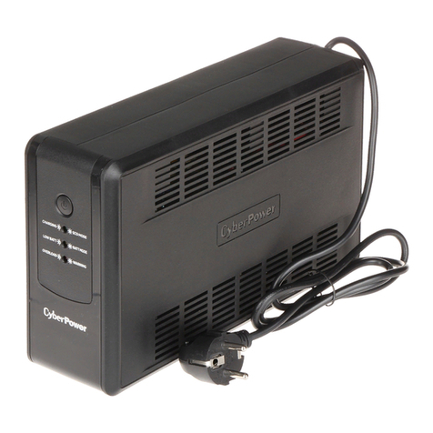
inform Pyramid Plus Specification sheet

288713405
Operating and Installation
manual for
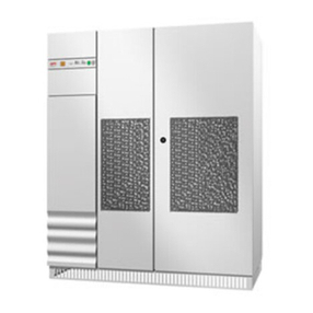
PYRAMID PLUS
10-200kVA
Uninterruptible Power Systems

288713405

288713405
C
CO
ON
NT
TE
EN
NT
TS
S
1. SAFETY………………. ......................................................................................................... 2
2. HANDLING………………...................................................................................................... 4
3. INSTALLATION .................................................................................................................. 5
3.1 Introduction………………...................................................................................................... 5
3.2 Unpacking…………… ………................................................................................................ 5
3.3 Equipment Positioning…………………….. ........................................................................... 5
3.4 Connection of Power Cables ................................................................................................ 6
3.4.1 Safety Earth……………………............................................................................................. 7
3.4.2 Cable Connection………...................................................................................................... 7
3.4.3 Battery Installation……………….. ........................................................................................ 12
3.4.4 Communication (UPS-Server)……………….. ...................................................................... 15
4. FRONT PANEL……. ............................................................................................................ 16
4.1 Introduction ………….. .......................................................................................................... 16
4.2 Alarms and Troubleshooting ................................................................................................. 17
4.3 Menu Description…….. ......................................................................................................... 20
4.4 Main Menu…………… .......................................................................................................... 22
4.5 Measures Menu Items…………………….. ........................................................................... 22
4.6 Alarms Menu Items…… ........................................................................................................ 22
4.7 Information Menu Items ........................................................................................................ 23
4.8 Settings Menu Items…… ...................................................................................................... 23
4.9 Command Menu Items.......................................................................................................... 24
4.10 Time Menu Items………........................................................................................................ 25
4.11 Password Menu Items.......................................................................................................... 25
5. OPERATING INSTRUCTIONS............................................................................................. 26
5.1 UPS Switch On Procedure 10 to 30kVA ............................................................................... 26
5.2 UPS Switch On Procedure 40 to 200kVA ............................................................................ 26
5.3 Transfer to Maintenance By Pass Mode 10 to 30kVA .......................................................... 27
5.4 Transfer to Maintenance By Pass Mode 40 to 200kVA……………………… ....................... 27
5.5 Transfer from Maintenance By Pass to Inverter Mode 10 to 30kVA .................................... 28
5.6 Transfer from Maintenance By Pass to Inverter Mode 40 to 200kVA .................................. 28
5.7 Transfer from Static By Pass to Inverter Mode ..................................................................... 29
5.8 UPS Shutdwon Procedure 10 to 30kVA…………………………………………………… ...... 29
5.9 UPS Shutdwon Procedure 40 to 200kVA…………………………………………………… .... 30
5.9.1 Utility Interruption…………………………………………………… ......................................... 30
6. PARALLEL OPERATION..........................................................................................................31
6.1 Introduction…………….. ....................................................................................................... 31
6.2 Parallel Operation Modes...................................................................................................... 31
6.2.1 Symetric Parallel Mode…………………………… ................................................................. 31
6.2.2 Parallel Redundant Mode………........................................................................................... 32
6.2.3 Hot Standby Mode………………........................................................................................... 32
6.3 Parallel Operation Mode Fault Codes................................................................................... 33
6.4 Parallel System Accessories................................................................................................. 33
6.5 UPS Switch On Procedures Parallel Mode ……………………………………………………..42
6.6 Transfer to Maintenance By Pass Mode ……………………………… .................................. 43
6.7 Transfer from Maintenance By Pass to Inverter Mode…….................................................. 43

288713405
7. REMOTE MONITORING AND CONTROL............................................................................ 44
7.1 Serial Link Interface……….………………… ......................................................................... 44
7.2 Serial Link Interface Cable ................................................................................................... 44
7.3 Modem Connection TELESERVICE .................................................................................... 45
7.3.1 Hardware Configuration……….. ........................................................................................... 45
7.3.2 Functioning Principle…………. ............................................................................................. 45
7.3.3 SMART Modem Programming (PC modem) ........................................................................ 45
7.3.4 DUMB Modem Programming ……………………………………………………….................. 45
7.3.5 DUMB Modem – UPS Connection Cable ............................................................................. 46
7.4 Dry Contact Interface Connection......................................................................................... 46
7.5 Remote Monitoring Panel...................................................................................................... 46
8. END USER GUIDE ............................................................................................................... 47
8.1 Maintenance……………….................................................................................................... 47
8.2 Storage……………………..................................................................................................... 47
9. LIMITED WARRANTY ............................................................................................................... 48

288713405 2
1
1.
.
S
SA
AF
FE
ET
TY
Y
Thank you for choosing Inform UPS Systems. This document provides all the instructions
necessary for the instllation and the operation of the PYRAMID-PLUS Uninterruptible Power
Supply.
For the staff and the equipment safety, it is necessary for the users to fully read and understand
this manual before working on this equipment.
DESCRIPTION OF THE SYMBOLS ON THE UPS:
DANGER DANGEROUS VOLTAGES (red-yellow)
READ THE OPERATING INSTRUCTIONS (black-yellow)
GROUNDING TERMINAL BLOCK (black-silver).
IMPORTANT NOTICES
1. Please read and save the manual before operating the system.
2. Please do not remove the protection panels; internal voltage is dangerous.
3. Please follow all the instructions and warnings.
4. Please do not operate the unit without grounded source.
5. Power cord of the UPS should be routed carefully so that they are not to be walked on.
6. Please save or recycle the packaging materials.
7. The equipment should be always kept in vertical position.
8. This equipment is compliant with the European directives, which shall be applied to this product.
Hence it is marked:
WARNING!
•Do not insert any object into ventilation holes or other openings.
•Avoid the sudden temperature changes, which could cause condensation inside the UPS.
Otherwise, wait for at least two hours before switching on.
•To reduce the risk of fire or electric shock, install in temperature and humidity controlled indoor
area.
•This equipment complies with standards EN50091-2 for electromagnetic compatibility. In a
domestic environment, it can cause radio interference; accordingly, complementary measures
must be made.
•To reduce the risk of fire, replace fuses with the same type and rating when necessary.

288713405 3
CAUTION!
•Only authorized person has to make installation or maintenance of UPS and batteries.
•Risk of electric shock! Please do not remove cover. No user serviceable parts inside,
please contact to authorized service.
•The output may be energized when the unit is not connected to a mains supply.
•Risk of electric shock! Hazardous live parts inside the unit are activated by the battery
supply even when the input AC power is not connected.
•Switch the UPS OFF before connecting the computer interface signal cable. Reconnect the
power cord only after signaling interconnections have been made.
BATTERY WARNINGS
•Risk of electric shock! The following precautions have to be taken during the operation on
battery:
* Remove watches, rings or other metal objects.
* Use tools with insulated handles.
•Batteries in the UPS are recyclable. Batteries must be disposed of according to local
environmental laws. If not disposed of properly, batteries contain lead and may cause danger for
the environment and human health.
•Do not dispose the batteries in a fire. Batteries will explode. Do not open or mutilate the
batteries. They contain an electrolyte that is toxic and harmful to the skin and eyes. In any
contact with the electrolyte, please wash the zone immediately.
•Please do not discharge the battery.

288713405 4
2
2.
.
H
HA
AN
ND
DL
LI
IN
NG
G
NOTE: THE UPS CABINETS MUST ALWAYS BE HANDLED VERTICALLY DURING
TRANSPORT.
Do take care to the UPS balancing during handlings.
Handling :
You can either use a pallet truck or
a lift truck for side handling,
provided that the removable side-
panel is unscrewed.
PYRAMID-PLUS
Battery cabinet UPS cabinet
It is possible to use slings provided
they are at least 1.5 m long.
Suitable lifting eyes with nuts can be
supplied on request.
Remove the top panel to gain
access to the 4 holes designed
for the fixing of the lifting eye
screws.
If the height of the ceiling does not
make it possible to use slings, use a
lifting beam with shorter slings.

288713405 5
3
3.
.
I
IN
NS
ST
TA
AL
LL
LA
AT
TI
IO
ON
N
Non-compliance with the installation guidelines contained in the present manual could adversely
effect the working and/or reliability of the UPS.
3.1 Introduction
WARNING!!!
•Do not apply electrical power to the UPS equipment before the arrival of authorized service
personnel.
•Installation and maintenance has to be done by authorized service person only.
3.2 Unpacking
The UPS is packed and enclosed in a structural cardboard carton to protect it from damage.
1. Inspect for damage that may have occurred during the transport, if any damage is noted, please
call the forwarder or insurance company immediately and retain the shipping carton and the
UPS.
2. Carefully open the carton and take the UPS out.
3. Keep the carton and packing material for future re-use.
3.3 Equipment Positioning
1. The equipment’s installation place must be easy to service.
2. Install the UPS in a protected area with adequate airflow and free of excessive dust.
3. You must therefore allow for a minimum gap of 250 mm behind the unit to allow adequate air
flow (See Figure 3.1)
4. Select a suitable place (temperature is between 0°C and 40°C) and the relative humidity (%90
max)
5. It is recommended to use air-conditioned room (24°C)
6. Temperature is a major factor in determining the battery life and capacity. Battery manufacturers
quote figures for an operating temperature of 20°C. On a normal installation the battery
temperature is maintained between 15°C and 25°C. Keep batteries away from main heat sources
or main air inlets etc.
7. In case of UPS operation in a dusty environment, please clean the air with a suitable air filtration
system.
8. Keep out of your equipment from the explosive and flammable items.
9. Avoid direct sunlight, rain, and high humidity.
WARNING!!! Check the capacity of the forklift if it is available for lifting.
DO NOT MOVE THE BATTERY CABINET WHILE THE BATTERIES ARE INSTALLED.

288713405 6
Air inlet are designed at the bottom
and the rear of the UPS, whereas air
outlet are located on the top of the
unit : it is therefore useless to leave a
lateral clear-distance.
Front face
3.4 Connection of Power Cables
CAUTION! Only authorized person has to install or maintain UPS / batteries.
The AC input of the UPS should be supplied by a separate line from the AC distribution board.
The input/output cables can be sized to suit the modules rating according to the table below.
The connections of the electric panel should be supplied by grounded outlet. Cables enter the UPS modules
via entry panels in the base of cabinet. All control cables should be screened and run in a separate trunking
to the power cables.
The input/output cables can be sized to suit the modules’ rating according to the table below.
NOMINAL CURRENT : Ampere / Recommended Cable Size (mm2) BUS BAR CONNECTION
STUD SIZE
Input Mains
With full battery Recharge
Bypass / output
At full load
380V 400V 415V 380V 400V 415V
Battery
at min.
Battery
Voltage
UPS
POWER
(kVA)
A / mm2A / mm2A / mm2A / mm2A / mm2A / mm2A / mm2
Input/Output
Cable
Terminations
U-V-W-N
Battery
Terminations
+ & -
10 22A / 6 20A / 6 19A / 6 16A / 6 15A / 6 14A / 6 28A / 6 16mm2
Terminals
16mm2
Terminals
15 32A / 6 30A / 6 28A / 6 23A / 6 22A / 6 21A / 6 41A / 10 16mm2
Terminals
16mm2
Terminals
20 43A / 10 39A / 10 37A / 10 31A / 10 29A / 10 28A / 10 55A / 16 16mm2
Terminals
16mm2
Terminals
30 64A / 16 59A / 16 56A / 16 46A / 10 44A / 10 42A / 10 82A / 25 35mm2
Terminals
35mm2
Terminals
40 85A / 25 78A / 25 73A / 25 61A / 16 58A / 16 56A / 16 110A / 35 M6 M8
60 128A / 35 117A / 35 109A / 35 91A / 25 87A / 25 84A / 25 163A / 50 M6 M8
80 168A / 50 160A / 50 154A / 50 121A / 35 115A / 35 111A / 35 220A / 70 M6 M8
100-120 256A / 70 234A / 70 218A / 70 182A / 70 174A / 70 168A / 70 326A/100 M8 M8
160 329A / 95 312A / 95 301A / 95 230A / 70 218A / 70 210A / 70 430A/120 M8 M8
200 357A /185 339A /185 327A /185 243A /150 230A /150 223A /150 560 /185 M8 M10
NOTES: The neutral conductor should be sized for 1,5 times the output/bypass phase current.
The Earth conductor should be sized at 2 times the output/bypass conductor (this is
dependent on the fault rating, cable lengths, type of protection etc.) These
recommendations are for guideline purposes only and are superceded by local
regulations and codes of practice.
Fi
g
ure 3-1 Installation Dia
g
ram
250
cm
PYRAMID
-
PLUS

288713405 7
3.4.1 Safety Earth
The safety earth cable must be connected to the earth BUS BAR and to each cabinets in the
system and also the earthing and neutral bonding arrangements must be in accordance with the
local laws.
ATTENTION!!! Failure to follow adequate earthing procedures can result in electric shock hazard
to personnel, or the risk of fire.
3.4.2 Cable Connections
ATTENTION!!! All the cable connections of the UPS must be done by the authorized service
person. Once the equipment has been finally positioned and secured, connect the power cables as
described in the following procedure:
Split (External) By-Pass
Supply Connections
a. The three white cables shown in
Figure 3-2 are removed.
b. The three phase + neutral cables
coming from the split by-pass supply
are connected to terminals U3-V3-
W3 and N3.
c. The three phase + neutral AC Input
cables are connected to terminals
U1-V1-W1 and N1, to supply the
necessary operational input power
of the UPS.
d. Note that in this connection the
neutrals of the split by-pass supply
and the line are connected together.
e. The split by-pass supply’s voltage
and frequency must be compatible
with the UPS output voltage and
frequency.
RECTIFIER
INPUT FUSES
BATTERY
FUSES
F1 F2 F3
+
BATT (+) BATT (-)
Figure 3-2-a 10-15-20 kVA Cable Connections
WHITE
CABLES
Figure 3-2-b 30 kVA Cable Connections
RECTIFIER
INPUT FUSES
BATTERY
FUSE
F1 F2 F3
+
INPUT
SUPPLY
S1
WHITE
CABLES
BATT (+) BATT (-)

288713405 8
1. Verify that the UPS’s switches are totally at “0” position.
2. Connect the AC input supply cables between the mains distribution panel and the UPS “AC Input” (U1-V1-
W1-N1) terminals.
ATTENTION!!! ENSURE CORRECT PHASE SEQUENCE
If there is a phase sequence fault, A21/A39 “ROTATE PHASE” message appears on
the front panel and the UPS can’t work.
3. Connect the UPS output cables between the UPS output “AC output” (U2-V2-W2-N2) and the load
distribution panel.
4. Make the connection of the battery groups. Please look at the Battery Installation item for it.
ATTENTION!!! Remove the battery fuse before making the connection of the battery circuit
breaker during the battery installation. (Turn off into “0” (OFF) position)
5. The “BATT(+)” and “BATT(-)” cables, coming from the battery group terminals must be connected to the
lower ends of the BATTERY “+” and “-” respectively.
6. If a battery circuit breaker is going to be used, it should be connected in series with the “BATT(+)” and
“BATT(-)” cables.

288713405 9
Figure 3-2-c 40-60 kVA UPS Power Connections
S
p
lit B
y
-Pass Connections
Normal Connections
B A
B A
AC
AC
AC
AC

288713405 10
Figure 3-2-d 80 kVA UPS Power Connections
S
p
lit B
y
-Pass Connections
Normal Connections
B
B A
A
AC
AC
AC
AC

288713405 11
1) Verify that the UPS’s switches are totally at “0” position.
2) Connect the AC input supply cables coming from the input mains distribution panel to the B
terminals as in Fig. 3-2-c,d,e.
ATTENTION!!! PLEASE BE SURE OF CORRECT PHASE SEQUENCE.
If there is a phase sequence fault, A21/A39 “ROTATE PHASE” message appears on the front
panel and the UPS can’t work.
THE CORRESPONDING AC INPUTS OF BOTH UPS’s (U3-V3-W3) MUST BE EXACTLY OF THE SAME PHASE.
3) Connect the UPS output cables from the output terminals to the load distribution panel.
ATTENTION!!! For proper load sharing during parallel operation the cables between the
AC distribution panel and the AC output terminals of one UPS must be
exactly the same size and length as the cables between the distribution
panel and the AC output terminals of the second UPS.
4) Make the connection of the battery groups. Please look at the 3.3 Battery Installation item for it.
Fi
g
ure 3-2-e 100-120-160-200 kVA UPS Power Connections
A
Output
connections
(To load)
B
Input
connections
C
UPS rectifier and inverter input connections. Normally
these terminals are not used for the input connections.
Split (External) By-pass Connection
a. Remove the shown links (in the figure)
b. Connect the R-S-T-N cables to the B terminals
from the external by-pass source.
c. Connect the mains input R-S-T-N cables to
the C terminals.
d. The external by-pass’s voltage and frequency
must be suitable With the UPS’s.
S1
These links
must be
removed for
split bypass
system
Battery power
connections
S2
S4
S3
U2
V2
W2
N2
U3
V3
W3
N3

288713405 12
ATTENTION!!! Remove the battery fuses before making the connection of the battery circuit
breaker during the battery installation. (Turn off into “0” (OFF) position)
5) Connect the copper earth bus, which is under the safety earth and the cables power connection.
Note: The earth and the neutral connections must be done according to national rules.
If the REMOTE STOP option is going to be used, you should connect the remote stop button
(normally open), to the pins 4 and 5 of the remote stop connector (CN3) on the PCB ITF3.
3.4.3 Battery Installation
ATTENTION!!! Remove the battery fuse before making the connection of the battery circuit
breaker box during the battery installation.
The batteries of the UPS equipment are usually contained in a purpose-built battery cabinet, which
sits alongside the main UPS equipment. Sealed, maintenance-free batteries are normally used in
this type of installations.
Where battery racks are used, they should be positioned in accordance with the battery
manufacturer’s recommendations. In general, batteries require a well-ventilated, clean and dry
environment at reasonable temperatures to obtain efficient battery operation.
In general a minimum space of 10 mm must be left on all vertical sides of the battery block. A
minimum clearance of 20 mm should be allowed between the cell surface and any walls. A
clearance of minimum150 mm should be allowed between the top of the cells and the underside of
the shelf above (this is necessary for monitoring and servicing the cells). All metal racks and
cabinets must be earthed. All live cell connections must be shrouded.
The batteries are connected to the UPS through a circuit breaker (optional), which is manually
closed and electronically tripped via the UPS control circuitry. If the batteries are cabinet-mounted
this circuit breaker is fitted within the cabinet; however, if the batteries are rack-mounted or
otherwise located remote to the main UPS cabinet then the battery circuit breaker must be mounted
as near as possible to the batteries themselves, and the power and control cables connected to the
UPS using the most direct route possible.
1. Unpack each battery and check its terminal voltage. If any battery has terminal voltage less than
10,5 V it must be charged before.
2. Please check the battery connecting materials.
3. Please put 8 pieces of the batteries to each rack.
4. Start installing the batteries from top to the bottom on the racks.
5. Connect the cable between the battery circuit breaker’s positive port (BAT+) first then battery
tray (+) at the left topside as in the figure 3-3
6. Connect the cable between the battery circuit’s negative port (BAT-) first then battery tray (-) at
the right bottom side as in the figure 3-3
7. Please pay attention to the connections and the poles’s directions between the racks.

288713405 13
8. Connect the battery circuit breaker’s “UPS(+) ⇒BATT(+)” and “UPS (-) ⇒BATT(-)” Ports to the
battery group connection terminals at the UPS cabinet.
9. Connect the shielded control cable between the UPS and the battery circuit breaker as in the
following.
Battery circuit Inside of the UPS
Breaker box
1.....................1 ITF3 Board
BAC60 Board 2.....................2 BATT. CB
CN1 3.....................3 CN3
Fi
g
ure 3-3-a UPS Battery Group Connection
(With Battery Fuse)
To UPS Cabinet
Battery
Fuse

288713405 14
Figure 3-3-b UPS Battery Group Connection
(With Battery Circuit Breaker)
(OPTIONAL)
To UPS
Cabinet
Control
Cable
Electronically
Controlled
Battery Circuit
Breaker
BAC60
1 2 3
CN1
To ITF3
CN3
Battery Circuit
Breaker Input Emergency
Stop

288713405 15
3.4.4 Communication (UPS-Server)
Dry relay alarm contacts or RS232 communication port can be used for communication with UPS. Users can
get information about any possible alarm like “Battery Low” “Line Failure” “Load On By-pass”. The relay
interface AS400 and Windows NT is an special edition for the systems.
You should use ITF3 and RS330 board for the communication with the PC. For this connections there must
be a dedicated serial port.
ATTENTION!!! The communication cables of this option must be shielded and must install away from the
voltage cables.
The RS232 port (at RS330 board and DB9 female) definition :
RS232 Signal Gnd (isolated) 7
RS232 Receive 6
RS232 Transmit 9
The settings for the Microsoft NT server, IBM AS400connections will be done by the system’s operator in
accordance to the each user’s needs.
Figure 3.4 ITF3 Board Connection Details
CN3 CN4
Battery Circuit
Breaker Input
Emergency Stop Line Failure
Relay
Battery Low Relay
or Common Alarm
Relay
By-Pass
Relay

288713405 16
4
4.
.
F
FR
RO
ON
NT
T
P
PA
AN
NE
EL
L
4.1 Introduction
The front panel of UPS, consisting of a 2 lines alphanumeric display, 6 status lamps, plus 4 function
keys, allows the complete monitoring of the UPS status. The mimic flow diagram helps to
comprehend the operating status of the UPS. By using the function keys operator can move on
menus and change some parameters.
Figure 4-1 Control and display panel
Line If lamp is lit mains is okay
Battery If lamp is lit UPS is operating on batteries
By-pass If lamp is lit static bypass is active and load is connected to mains voltage
Maint.Sw. If lamp is lit mechanical bypass switch is on
Inverter If lamp is lit inverter feeds the load
O/P Sw. If lamp is lit S4 power output switch “1” on position.
There are 4 function keys on front panel these are ENTER, DOWN, PLUS and MINUS.
DOWN key helps moving on menus, PLUS and MINUS keys select options , ENTER key means
the selected option or menu is valid.

288713405 17
4.2 Alarms and Troubleshooting
Totally 64 alarms and status messages (might be extended, please consult us) are used in UPS,
which helps the user. Messages are coded for easy dialog with service organization, all messages
contains numbers A1-A2-A3….An. Messages and events in UPS are recorded to a log file with
event time and date
ALARM DESCRIPTION
A1 BYPASS FAILURE Bypass system failure
Possible Causes: 1) Maybe bypass parts are defective call service
A2 INVERTER FAILURE Inverter digital start system is failed
Possible Causes: Internal failure. Call service.
A3 3 OVERTEMP Overload in UPS repeated at 3 times in 30 min.
Possible Causes: 1) Overload
2) Fan failure or durty air inlets,outlets
3) Bad UPS settling
A4 OUT FAILURE UPS output voltage is out of tolerance at 3 times in 30 min.
Internal failure. Call service.
A5 BATT AUT END Batteries empty at last of line out. Wait to return of electric.
A6 CHARGER FAULT Rectifier is not to produce DC bus voltage.
A7 BATTERY LOW Batteries are low.
Possible Causes: 1) UPS wrought long time when line out
2) Charger system failure
A8 OUTPUT HIGH Inverter output voltage is over than max. tolerance voltage value.
Inverter is stopped.
Possible Causes: 1) Inverter failure
A9 OVERLOAD UPS loaded over than max. %100 load level.
Possible Causes: Load on the UPS output is over than max. Load capacity. This state is maybe
continous or short time. When this alarm is continous to check loads.
A10 LINE FAILURE Line failure.
Possible Causes: 1) Maybe line out
2) There is a problem on the UPS ınput board. Please Check.
3) UPS input fuses are blowned.
A11 HIGH TEMPER Over temperature. (inverter or rectifier section)
Possible Causes: 1) Overload for inverter
2) Over temperature
3) Fan failure or durty air inlets
4) Bad UPS settling. There is not vantilation area.
A12 IGBT FAILURE Inverter output system failure.
Possible Causes: 1) Overload.
2) Short circuit.
3) UPS is out of order. Call service.
A13 OUTPUT LOW Inverter output voltage is under than min. tolerance voltage value.
Inverter is stopped.
A14 BATTERY HIGH Battery voltage is over than max. tolerance.
A15 FUSE FAILURE Fuse blowned. (not used at this power range)
A16 BYP INPUT BAD
During transfer to bypass, Voltage or frequency value of bypass source is
incorrect and the UPS turn off the load power.
During normal (inverter) operation some times you can see this message.
During bypass if the bypass protection option is on and if the bypass source is
tolerant out UPS switch off the static bypass for load protection.
A17 BATT CB OPEN
Battery circuit breaker is off, batteries are not connected to UPS
At start up if the mains is okay you can start operation but this message is
active
At start up during line failure UPS waits for turn on battery CB and then it starts
Table of contents
Other inform UPS manuals
inform
inform GUARDIAN User manual
inform
inform InfoSTS User manual
inform
inform Informer 1000VA User manual
inform
inform DSP FLEXIPOWER SERIES User manual
inform
inform PYRAMID DSP PREMIUM Series User manual
inform
inform 500 User manual
inform
inform Guard 500VA User manual
inform
inform DSP User manual
inform
inform PDSP31010 User manual
inform
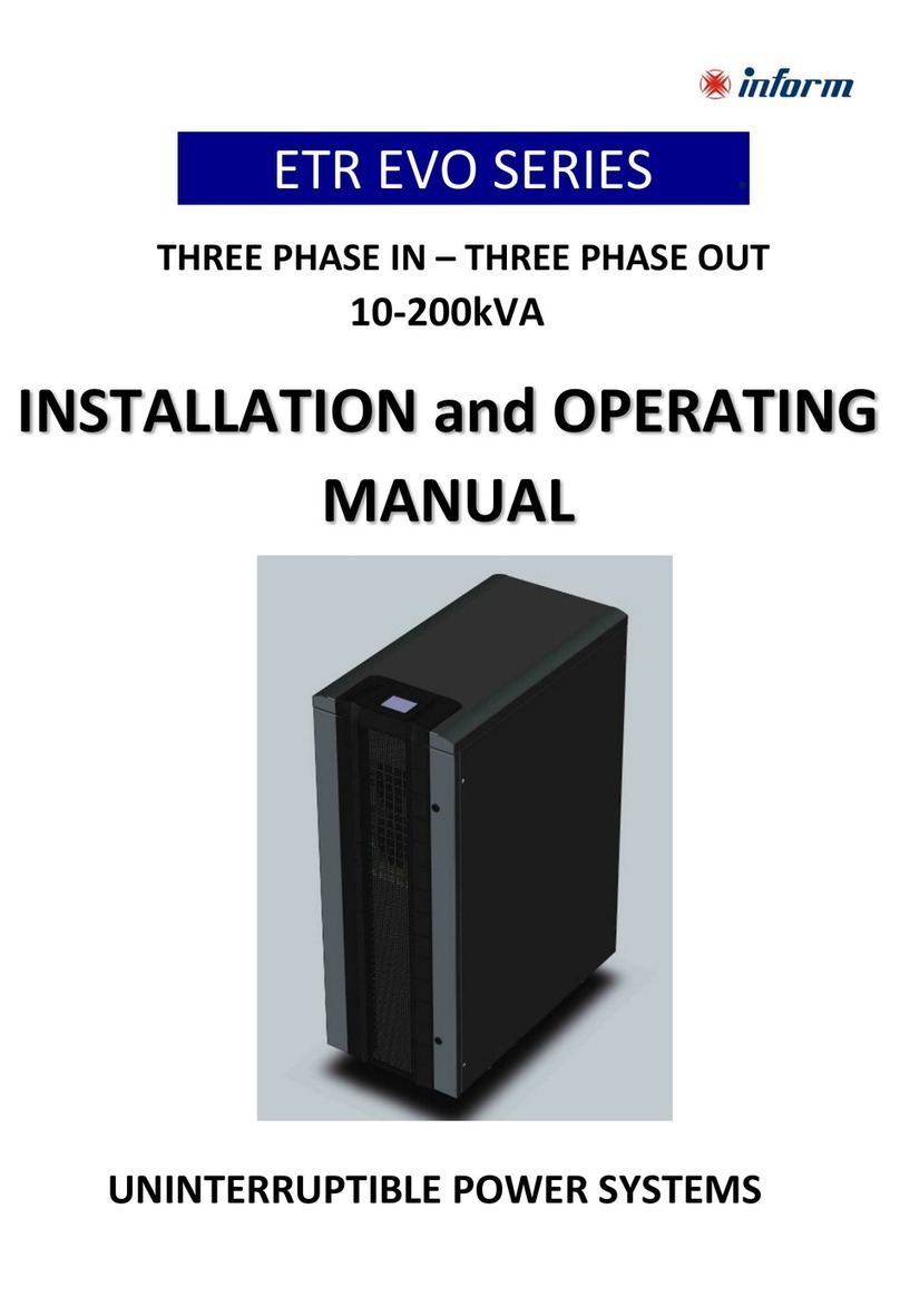
inform ETR EVO Series User manual
