Sonny's HY345 User manual

Owner’s Manual
_____________________________________________________________________________________
Hydraulic Power Pack
Register Your
Warranty
Scan QR Code
Designed here. Built here. Backed here.™

Hydraulic Power Pack Owner’s Manual
=============================================================================================================
© 2021 SONNY’S The CarWash Factory®. All Rights Reserved. SonnysDirect.com
This document is confidential and proprietary to SONNY’S and cannot be used, disclosed, or published without prior written consent.
Content, prices, and availability subject to change without notice
Manual-O, Hydraulic Power Pack –Part # 10013914-B
Page 2 of 32
Sonny’s and Sonny’s The CarWash Factory are Registered trademarks of Sonny’s Enterprises LLC
Make CarWashing Easy and OneWash are trademarks of Sonny’s Enterprises LLC
Designed here. Built here. Backed here. is a trademark of Sonny’s Enterprises LLC
Products mentioned herein are for identification purposes only and may be registered trademarks of their respective companies.
All other brand names, trademarks or registered trademarks are the property of their respective owners.
Hydraulic Power Pack Owner’s Manual
=============================================================================================================
© 2021 SONNY’S The CarWash Factory®. All Rights Reserved. SonnysDirect.com
This document is confidential and proprietary to SONNY’S and cannot be used, disclosed, or published without prior written consent.
Content, prices, and availability subject to change without notice
Manual-O, Hydraulic Power Pack –Part # 10013914-B
Page 3 of 32
TABLE OF CONTENTS
READ ALL INSTRUCTIONS PRIOR TO OPERATING
4
IMPORTANT SAFEGUARDS AND WARNINGS
4 - 6
INTRODUCTION
7
HYDRAULIC POWER PACK FEATURES
8
UTILITY REQUIREMENTS
9
HYDRAULIC POWER PACK CAPABILITIES
10 - 11
HYDRAULIC POWER PACK SELECTION
12 - 14
SAFETY WEAR REQUIRED FOR INSTALLATION
15
TOOLS REQUIRED FOR INSTALLATION
15
INSTALLATION INSTRUCTIONS
16
ADJUSTMENTS AND TESTING
17 - 18
GENERAL OPERATION
19
MOTOR, PUMP & PARTS WARRANTY
19
GENERAL WARRANTY
20
REGISTER YOUR WARRANTY ONLINE
20
PREVENTIVE MAINTENANCE
21
MAINTENANCE VIDEO
21
Sonny’s CarWash College
22
CUSTOMER SERVICE & TECHNICAL SUPPORT
23
FREQUENTLY ASKED QUESTIONS
24
YOUR BUSINESS IS IMPORTANT TO US
25
ONLINE PRODUCT MANUALS & TECH BULLETINS
26
FREE NEWSLETTERS AND ALERTS
27
FREE CAR WASH CATALOGS & BOOKS
28
EMERGENCY CONTACTS
28
UNLIMITED WASH CLUB
29
CONTROL YOUR PROFITABILITY
30
SECURITY AT YOUR FINGERTIPS
30
GROW YOUR BUSINESS
31

Hydraulic Power Pack Owner’s Manual
=============================================================================================================
© 2021 SONNY’S The CarWash Factory®. All Rights Reserved. SonnysDirect.com
This document is confidential and proprietary to SONNY’S and cannot be used, disclosed, or published without prior written consent.
Content, prices, and availability subject to change without notice
Manual-O, Hydraulic Power Pack –Part # 10013914-B
Page 4 of 32
•This manual is a comprehensive step-by-step user instruction guide for the Hydraulic Power Pack
and components. To review other manuals go online to SonnysDirect.com under Support Tab.
•Make sure to read, understand and follow all these instructions.
•To address any questions relating to ordering parts, operating the Hydraulic Power Pack,
installation, troubleshooting, maintenance, service or anything else, contact Sonny’s Technical
Support Team at 1-800-327-8723, Ext: 234.
•All deviations and alterations from these instructions MUST be reported to Sonny’s The CarWash
Factory®. Keep this manual in a location where it may be used for ongoing reference.
•WARNING: Do not perform any maintenance or work on equipment unless you first perform
Lock-Out Safety Precautions. All electrically powered equipment MUST have manually
operated disconnects capable of being locked in the “OFF” position. Equipment that has been
“locked out” for any reason must be restarted ONLY by the person who performed the “lock
out” operation. These procedures MUST be followed to avoid personal injury, death and/or
dismemberment.
•All parts and components MUST be installed by experienced and trained technicians.
•No unauthorized personnel should ever be permitted in the wash tunnel or near the equipment at any
time.
•Hardhat, safety glasses with side shields, closed steel toe shoes, anti-impact and cut resistant
gloves, dust mask, and earplugs if operating power tools, MUST be worn.
•When cutting or grinding any metal, safety glasses, earplugs, and dust mask MUST be worn.
•Do NOT leave a ladder or any other items such as wash down hoses or tools in the wash
tunnel while equipment is running. Vehicle damage and injury, including death, can occur.
•Do NOT wear loose fitting clothing or jewelry around moving equipment. Do not allow any part
of your body or other objects (including ladders, hoses, or tools) to come in contact with
moving equipment. Entanglement may result causing injury, death, or dismemberment.
•Always exercise caution when walking (never run) through the wash tunnel as there may be slippery
conditions. Be careful so you do not bump into or trip over equipment.
READ ALL INSTRUCTIONS PRIOR TO OPERATING
IMPORTANT SAFEGUARDS AND WARNINGS

Hydraulic Power Pack Owner’s Manual
=============================================================================================================
© 2021 SONNY’S The CarWash Factory®. All Rights Reserved. SonnysDirect.com
This document is confidential and proprietary to SONNY’S and cannot be used, disclosed, or published without prior written consent.
Content, prices, and availability subject to change without notice
Manual-O, Hydraulic Power Pack –Part # 10013914-B
Page 5 of 32
•Electrical connections and repairs MUST ONLY be performed by a Licensed Electrician.
•Plumbing connections and repairs MUST ONLY be performed by a Licensed Plumber.
•When working on any equipment that is higher than your shoulders, always use a fiberglass ladder
that is in good condition.
•Use proper lifting technique. Team lifts are required for items over 50 lbs.
•Do NOT alter or modify parts in any way and do NOT interchange or substitute any components
without the authorization of your supervisor and Sonny’s The CarWash Factory.
•Do NOT install any parts or components into faulty materials.
•All damages and defects MUST be reported to both your supervisor and Sonny’s The CarWash
Factory.
•If there are any malfunctions with the Hydraulic Power Pack; or if any questions arise regarding the
equipment operations, immediately contact your supervisor or Sonny’s The CarWash Factory.
•Only use approved hardware, parts, and components with the Hydraulic Power Pack or any other
equipment.
•Protect your body parts against sharp corners and edges at all times.
•Keep loose articles of clothing and jewelry away from the removal, installation, or operation of all
equipment.
•The personnel installing the Hydraulic Power Pack are responsible for making sure it works
according to the instructions in this manual.
•Always remove ladders, tools, parts, etc, from the wash tunnel when finished.
•All personnel MUST be trained in the safe operation of all equipment, wash tunnel operations, safety
regulations, emergency shutdown and maintenance practices to avoid any accidents.
•Only personnel specifically instructed and trained are permitted to enter the wash tunnel to perform
inspections or maintenance. At least two qualified maintenance personnel MUST be present when
performing equipment repairs or preventive maintenance.
•IMPORTANT: Call Technical Support to adjust wash cycle when new equipment is installed.
•WARNING: All hydraulic and electrical systems in the wash tunnel equipped with a torque relief or
overload should be checked and set to the minimum amount that will allow for proper functionality
under normal washing conditions.
IMPORTANT SAFEGUARDS AND WARNINGS

Hydraulic Power Pack Owner’s Manual
=============================================================================================================
© 2021 SONNY’S The CarWash Factory®. All Rights Reserved. SonnysDirect.com
This document is confidential and proprietary to SONNY’S and cannot be used, disclosed, or published without prior written consent.
Content, prices, and availability subject to change without notice
Manual-O, Hydraulic Power Pack –Part # 10013914-B
Page 6 of 32
•WARNING: Possible wet floors and slippery conditions! To avoid an accident that might result in personal
injury, death or dismemberment, all personnel MUST proceed with Caution.
•WARNING: Do NOT enter the wash tunnel when the equipment is operating. Personal injury, death and/or
dismemberment may occur.
•WARNING: Make sure the proper Chemistry (Brush Lubrication) is being used in the Car Wash Tunnel to
prevent vehicle and/or equipment damage.
•WARNING: If the Equipment Installation Dimensions at the time of installation are NOT measured correctly, it
may result in equipment damage and/or failure. Dimensions MUST be verified if equipment is already installed.
Contact Sonny’s Technical Support Team at 1-800-327-8723, Ext: 234 for any Installation questions.
•WARNING: All connections and repairs MUST ONLY be performed by Licensed Professionals. Perform all
trade work in compliance with all applicable local and national codes.
•WARNING: Although building codes have been considered in developing all drawings, verification of site-
specific conditions and compliance with federal, state, and local building codes is the exclusive responsibility of
the customer and/or architect and engineer to verify compliance.
•WARNING: Do NOT attempt to repair or adjust any pressurized liquid or pneumatic part, hose, pipe, or fitting
while that equipment is in operation.
•WARNING: Do NOT operate any equipment that requires safety covers with those covers removed or
improperly installed. Do NOT operate any equipment if any component of that equipment is suspected to be
defective or malfunctioning.
•WARNING: Store all cleaning, washing solutions and oils in a well-ventilated area. Clean up fluid spills
immediately to prevent hazardous safety conditions. Be certain to follow all safety procedures on SDS Sheets
for each chemical product used.
•WARNING: When a piece of equipment must be in operation during inspection or maintenance, one qualified
technician must stay at the power disconnect switch while another qualified technician performs the inspection
or maintenance.
•WARNING: All Equipment MUST be given regular maintenance to prevent equipment damage and/or failure
that will VOID the warranty.
•WARNING: Emergency “STOP” Buttons MUST be well marked, and their location and proper use reviewed
with all personnel. Any activated “STOP” button must be reset only by the person who activated it. Clear the
wash tunnel of any people, ladders, hoses, tools, and other loose items before restarting the equipment. An
audible device MUST sound to warn people that the equipment is starting.
SAVE THESE INSTRUCTIONS
IMPORTANT SAFEGUARDS AND WARNINGS

Hydraulic Power Pack Owner’s Manual
=============================================================================================================
© 2021 SONNY’S The CarWash Factory®. All Rights Reserved. SonnysDirect.com
This document is confidential and proprietary to SONNY’S and cannot be used, disclosed, or published without prior written consent.
Content, prices, and availability subject to change without notice
Manual-O, Hydraulic Power Pack –Part # 10013914-B
Page 7 of 32
INTRODUCTION
Hydraulic Power Pack Owner’s Manual
=============================================================================================================
© 2021 SONNY’S The CarWash Factory®. All Rights Reserved. SonnysDirect.com
This document is confidential and proprietary to SONNY’S and cannot be used, disclosed, or published without prior written consent.
Content, prices, and availability subject to change without notice
Manual-O, Hydraulic Power Pack –Part # 10013914-B
Page 8 of 32
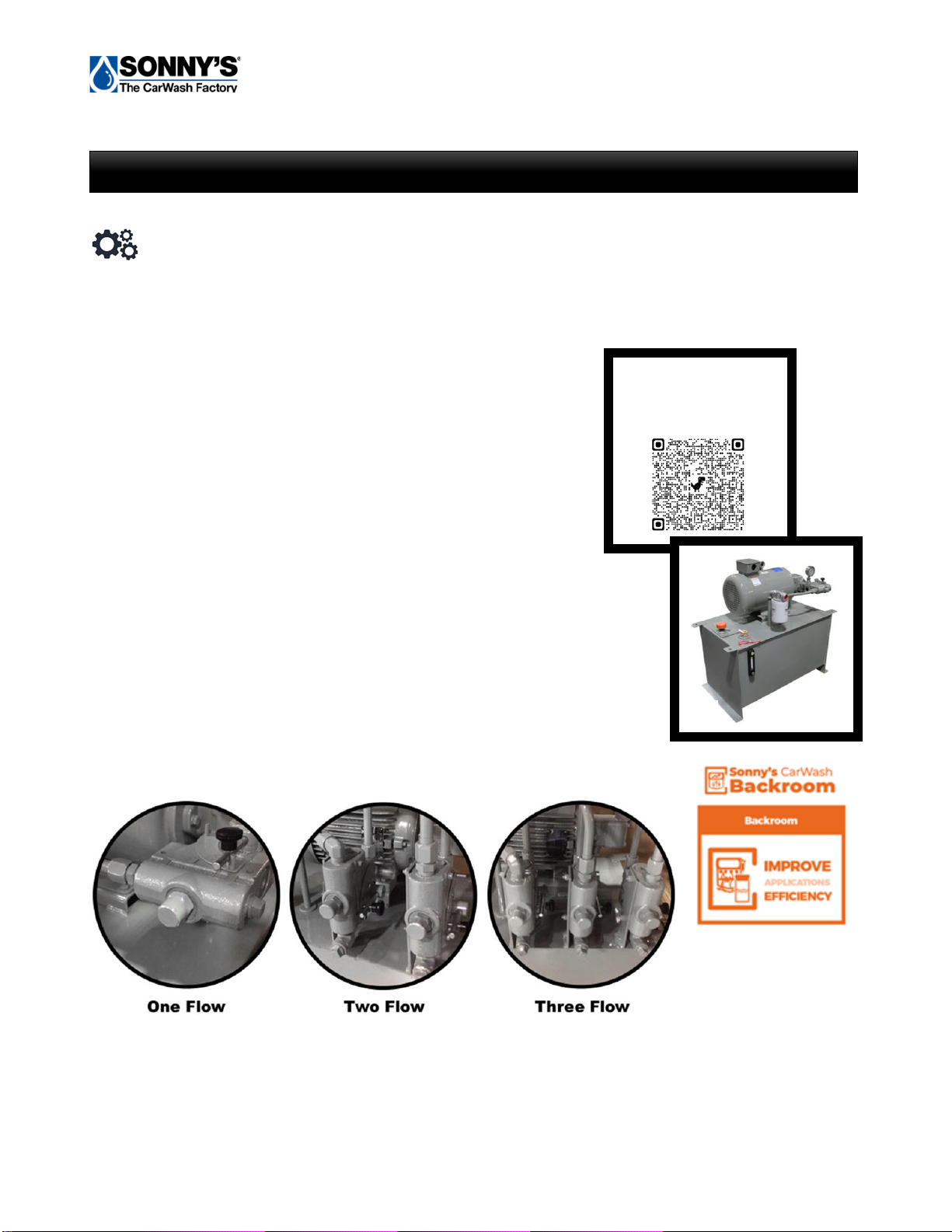
Sonny's Hydraulic Power Packs feature durable Vickers Vane®pumps engineered to excel in the
harsh environment of a professional car wash. They deliver reliable performance day after day with
minimal maintenance.
➢Sight Glass & Temperature Gauge
➢Return Line Filter
➢Filler Breather
➢Clean-Out Cover(s)
➢Suction Strainer
➢System Relief
➢Pressure-Compensated Flow Control
➢Pressure Gauge
➢Low Level Switch
➢Vickers Gear Pump on 3HP
➢Vickers Vane®Pump Available on 5, 7.5, 10, 15, 20 HP
➢Vickers Piston Pump Available on 7.5,10,15, 20 HP
HYDRAULIC POWER PACK FEATURES
Learn More
Scan QR Code

Hydraulic Power Pack Owner’s Manual
=============================================================================================================
© 2021 SONNY’S The CarWash Factory®. All Rights Reserved. SonnysDirect.com
This document is confidential and proprietary to SONNY’S and cannot be used, disclosed, or published without prior written consent.
Content, prices, and availability subject to change without notice
Manual-O, Hydraulic Power Pack –Part # 10013914-B
Page 9 of 32
Utilities interconnection and the materials required for interconnection to Sonny’s
equipment are the responsibility of the customer!
All connections and repairs MUST ONLY be performed by Licensed Professionals.
Perform all trade work in compliance with all applicable local and national codes.
Hydraulic
•The installer is to provide materials, install pressure, and return lines to and from the
hydraulic power pack flow control valves and the equipment to be operated. These lines
may be Schedule 80 BIP, or hose rated at least 2200PSI. Minimum 18 inch long flexible
hose should be used at each termination. It is recommended that the return line from the
last hydraulic motor in a circuit to the power pack return filter be one size larger than the
pressure line (example: pressure line is ½ inch… return line should be ¾ inch). This
practice extends the life of the hydraulic motors and pump by reducing line friction and oil
temperature.
Electrical
•The Customer’s Electrician is to provide materials and install 208VAC or 230VAC or
460VAC, 3-phase, 60Hz power to the electric motor on the hydraulic power pack from a
properly sized three pole circuit breaker and motor starter with three thermal overloads.
•The Customer’s Electrician is to provide materials and install single phase power (24VAC
or 110VAC) from the Customer supplied start/stop system, through the low oil level switch
on the hydraulic power pack to the motor starter coil for the hydraulic power pack.
Technical Disclaimer
Although building codes have been considered in developing all drawings, verification of
site-specific conditions and compliance with federal, state, and local building codes, it is
the exclusive responsibility of the customer and/or architect and engineer to verify
compliance.
UTILITY REQUIREMENTS
Hydraulic Power Pack Owner’s Manual
=============================================================================================================
© 2021 SONNY’S The CarWash Factory®. All Rights Reserved. SonnysDirect.com
This document is confidential and proprietary to SONNY’S and cannot be used, disclosed, or published without prior written consent.
Content, prices, and availability subject to change without notice
Manual-O, Hydraulic Power Pack –Part # 10013914-B
Page 10 of 32
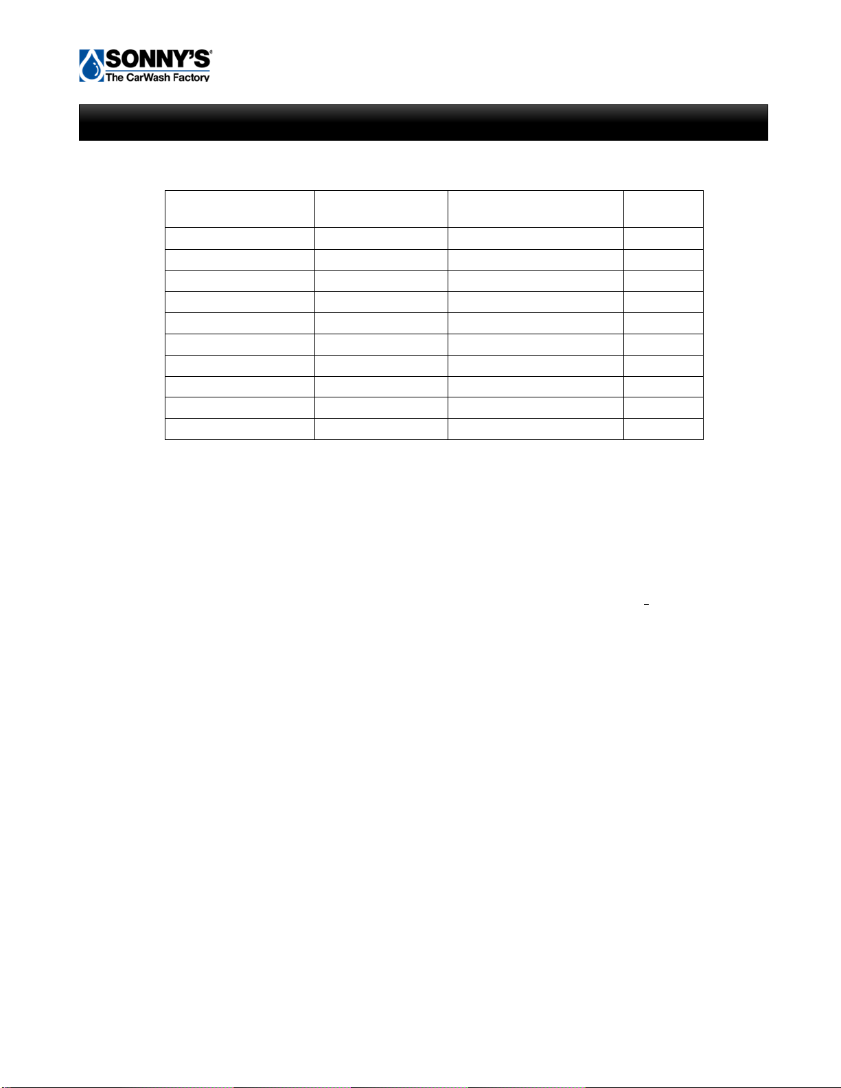
Hydraulic Motor Chart
Model
HP
GPM
Capacity
in Gallons
HY345
3
4.5
11
HY575
5
7.5
25
HY7510
7.5
10.5
25
HY10124
10
12.3
25
HY151840
15
19.5
40
HY202440
20
33
80
HY7VAR
7.5
10.5
25
HY10VAR
10
12.3
25
HY15VAR
15
19.5
60
HY20VAR
20
33
60
One 5HP Power Pack with 7.5GPM pump can operate
One pair of tire brushes plumbed in series, running at 300RPM with 4.5 cu in/rev motors
(5.9GPM fluid requirement)
OR
Four side washers plumbed in parallel with separate speed control valves running at 80RPM,
each using 5.9 cu in/rev motors (6.13GPM total fluid requirement)
One 7.5HP Power Pack with 10.5GPM pump can operate
A surface mount or over-under conveyor 100 ft. long or shorter at 120CPH (assumes 15RPM drive
sprocket with 5.2:1 speed reducer) using a high torque / low speed hydraulic motor
24.0 cu in/rev (8.1GPM fluid requirement)
OR
One pair of wraps or high side washers plumbed in parallel with separate speed control valves running at
80RPM, each using 9.7 cu in/rev motors (6.72GPM total fluid requirement)
OR
One pair of low side washers plumbed in series running at 80RPM with 5.9 cu in/rev motors, one pair of
high side washers plumbed in series running at 80RPM with 11.3 cu in/rev motors,
and one pair of tire washers plumbed in series running at 200RPM with 4.5 cu in/rev motors using a flow
divider and 3 speed control valves (total fluid requirement of 8.37GPM)
HYDRAULIC POWER PACK CAPABILITIES
Hydraulic Power Pack Owner’s Manual
=============================================================================================================
© 2021 SONNY’S The CarWash Factory®. All Rights Reserved. SonnysDirect.com
This document is confidential and proprietary to SONNY’S and cannot be used, disclosed, or published without prior written consent.
Content, prices, and availability subject to change without notice
Manual-O, Hydraulic Power Pack –Part # 10013914-B
Page 11 of 32
One 10HP Power Pack with 12.3GPM pump can operate
A surface mount or over-under conveyor longer than 100 ft. at 150CPH (assumes 15RPM drive
sprocket with 5.2:1 speed reducer) using a high torque / low speed hydraulic motor 24 cu in/rev
(10.12GPM fluid requirement)
OR
A surface mount or over-under conveyor longer than 100 ft. at 150CPH (assumes 15RPM drive
sprocket with 5.2:1 speed reducer) using a medium torque / medium speed hydraulic motor
14.9 cu in/rev (6.3GPM fluid requirement)
OR
One pair of low side washers plumbed in series running at 80RPM with 5.9 cu in/rev motors,
one pair of wraparound washers plumbed in parallel running at 80RPM with 11.3 cu in/rev
motors, and one pair of high side washers plumbed in series running at 80RPM with 11.3 cu
in/rev motors using 4 speed control valves (total fluid requirement of 10.35GPM)
NOTE
Recommended shaft speed for Tire Brushes with plastic bristles is 300-400RPM.
Recommended shaft speed for Washers with cloth is 60-70RPM.
Recommended shaft speed for Washers with NeoGlide is 80-90RPM.
HYDRAULIC POWER PACK CAPABILITIES
Hydraulic Power Pack Owner’s Manual
=============================================================================================================
© 2021 SONNY’S The CarWash Factory®. All Rights Reserved. SonnysDirect.com
This document is confidential and proprietary to SONNY’S and cannot be used, disclosed, or published without prior written consent.
Content, prices, and availability subject to change without notice
Manual-O, Hydraulic Power Pack –Part # 10013914-B
Page 12 of 32
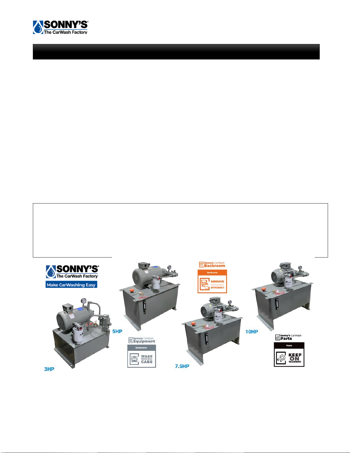
The correct power pack selection is important to your operation for long term reliability and
maintenance cost control. Reliability and less maintenance can be achieved partly by sizing a
hydraulic power pack so that it’s full running load, in gallons per minute, is approximately 80% of
the maximum rating of the power pack pump.
Additionally, an operating back-up power pack for key equipment will be most appreciated during
an unexpected breakdown. For example, if your conveyor power pack is a 7.5HP, 10.5GPM unit,
you could select the same size power pack for your tire brush equipment. By placing these two
power packs side by side you can easily switch the hydraulic lines should there be a problem
with the conveyor power pack. Your cash register won’t ring if the conveyor is not operating but
you can still process vehicles without the tire brushes turning.
Sizing a hydraulic power pack is not difficult. One simple formula, and a few minutes of your time
to calculate hydraulic motor loads is well worth the effort. Multiple outputs from one power pack
(not to exceed the maximum gpm delivery of the power pack pump) can be achieved by
plumbing pressure compensated speed control valves in a “daisy chain” method.
The formula for determining hydraulic motor demand in gallons per minute (GPM) is:
equipment shaft rotation rpm X cu in/rev rating of the hydraulic motor
231
= required GPM of pumped hydraulic fluid
SPECIAL NOTE: Series, or parallel, plumbing of hydraulic drive motors must be taken
into consideration when sizing a power pack.
Series plumbed motors may be calculated as one motor provided they are the same
cu in/rev displacement.
Parallel plumbed motors must be calculated as separate fluid loads and their total usage
in GPM added for a total GPM power pack requirement.
HYDRAULIC POWER PACK SELECTION

Hydraulic Power Pack Owner’s Manual
=============================================================================================================
© 2021 SONNY’S The CarWash Factory®. All Rights Reserved. SonnysDirect.com
This document is confidential and proprietary to SONNY’S and cannot be used, disclosed, or published without prior written consent.
Content, prices, and availability subject to change without notice
Manual-O, Hydraulic Power Pack –Part # 10013914-B
Page 13 of 32
A Few Examples for Using the Selection Formula are:
Example #1: A pair of cloth equipped wraparound washers using 11.3 cu in/rev motors
plumbed in parallel needs a new power pack.
90 rpm X 11.3 cu in/rev
231
= 4.40 GPM per motor
= 8.80 GPM for two #1005 motors in parallel
Therefore, a 7.5HP power pack with a 10.5GPM pump with two pressure compensated speed
control valves will meet the needs of this equipment fluid demand.
Example #2: You want to run a pair of low side washers using 5.9 cu in/rev motors plumbed in
series, a pair of van side washers using 11.3 cu in/rev motors plumbed in series, and a pair of
tire brushes using 4.5 cu in/rev motors plumbed in series all on using one power pack.
Side Washers 80 RPM X 5.9 cu in/rev
231
= 2.04 GPM
Van Washers 80 RPM X 11.3 cu in/rev
231
= 3.91 GPM
Tire Washers 350 RPM X 4.5 cu in/rev
231
= 6.82 GPM
Total GPM required 12.77 GPM
HYDRAULIC POWER PACK SELECTION

Hydraulic Power Pack Owner’s Manual
=============================================================================================================
© 2021 SONNY’S The CarWash Factory®. All Rights Reserved. SonnysDirect.com
This document is confidential and proprietary to SONNY’S and cannot be used, disclosed, or published without prior written consent.
Content, prices, and availability subject to change without notice
Manual-O, Hydraulic Power Pack –Part # 10013914-B
Page 14 of 32
Therefore, a 15HP power pack with a 19.5GPM pump with three pressure compensated speed
control valves will meet the needs of this equipment fluid demand.
Example #3: A power pack is needed for a 100 ft. long over and under conveyor that will
generally run at 120CPH (Cars Per Hour) using a 14.9 cu. in./rev. motor coupled to a 5.2:1 ratio
speed reducer. In this application there is 32 inches of conveyor chain travel per drive sprocket
revolution. 120 cars per hour equals one pusher roller traveling approximately 40 ft. per minute.
480 inches pusher roller travel per minute
32 in. conveyor chain travel per drive sprocket revolution
= 15 RPM for drive sprocket X 5.2 speed reduction
= 78 RPM of hydraulic drive motor shaft
78 RPM X 14.9 cu in/rev
231
= 5.03 GPM hydraulic fluid required for 120 CPH
Allowing for conveyor chain speed increases above 120CPH for this 100 ft. long conveyor a
7.5HP, 10.5GPM hydraulic power pack would be chosen.
NOTE
Hydraulic fluid requirements, in gallons per minute, from the power pack pump will vary with a change in the size of
the conveyor hydraulic drive motor as well as a change in the speed of the conveyor chain movement. Always
calculate conveyor power pack requirements using the highest conveyor chain speed and the largest (in cu in/rev)
hydraulic drive motor that your location would run.
Refer to the conveyor hydraulic motor speed and torque notes in the Motor Chart in this section to determine your
motor needs as they relate to high and low speed and high and low torque.
Some high speed, low torque hydraulic drive motors will stall if the conveyor chain is adjusted to a very slow speed.
Also, some low speed, high torque hydraulic motors will “top out” at chain speeds that may not be fast enough for
high production.
A method to handle the slow conveyor speeds of off-season washing and the high conveyor speeds of the peak
washing season is to have both high torque / low speed and low torque / high speed hydraulic motors on hand. This
helps to cure the very slow conveyor speed problem by mounting the high torque / low speed motor in that slower
season as well as providing an on the-shelf spare hydraulic motor at all times.
HYDRAULIC POWER PACK SELECTION
Hydraulic Power Pack Owner’s Manual
=============================================================================================================
© 2021 SONNY’S The CarWash Factory®. All Rights Reserved. SonnysDirect.com
This document is confidential and proprietary to SONNY’S and cannot be used, disclosed, or published without prior written consent.
Content, prices, and availability subject to change without notice
Manual-O, Hydraulic Power Pack –Part # 10013914-B
Page 15 of 32
WARNING: Make sure to follow Local and State Safety Wear Required Regulations to
ensure the safety of all personnel. Failure to follow Safety Regulations may result in
personal injury, death and/or dismemberment.
Tools
Not Included
Safety Glasses
Stainless Shims
½" Drive Ratchet Set
Standard Combo Wrenches
Standard Screwdriver
1” Hammer Drill
Sledgehammer
Tape Measure
SAFETY WEAR REQUIRED FOR INSTALLATION
TOOLS REQUIRED FOR INSTALLATION

Hydraulic Power Pack Owner’s Manual
=============================================================================================================
© 2021 SONNY’S The CarWash Factory®. All Rights Reserved. SonnysDirect.com
This document is confidential and proprietary to SONNY’S and cannot be used, disclosed, or published without prior written consent.
Content, prices, and availability subject to change without notice
Manual-O, Hydraulic Power Pack –Part # 10013914-B
Page 16 of 32
All parts and components MUST be installed by experienced and trained technicians.
Safety wear is required for ALL personnel.
WARNING: No climbing or standing on top of unit.
Work Force
Check
Installation Time
Check
2 Experienced
and Trained Technicians
1 to 2 Hours
Without Setbacks
1. Determine where the Power Packs are to be installed.
2. Sweep any debris from where the pack will sit.
3. Bring the Power Pack into the building and set it in place.
4. Lag the Power Pack down, and shim as needed.
5. If mounting a second Power Pack above this one; install the 4 stacking legs onto the
Power Pack, lift the second Power Pack into place and bolt it to the stacking legs.
WARNING: Verify stacking legs are installed correctly and secured with proper
hardware. Make sure second Power Pack is secured in place before lifting and mounting it
on top of the first Power Pack to avoid personal injury, death and/or dismemberment.
6. Thread the 90 into the output port of the flow control valve for the top Power Pack. Tighten
the fitting.
7. Thread the 90 into the input on the return filter and tighten.
8. Repeat steps 6 & 7 for the top Power Pack if it was installed.
9. Install the gauges for both Power Packs.
10.Fill the reservoirs with oil.
11.Connect feed and return lines before operating.
INSTALLATION INSTRUCTIONS

Hydraulic Power Pack Owner’s Manual
=============================================================================================================
© 2021 SONNY’S The CarWash Factory®. All Rights Reserved. SonnysDirect.com
This document is confidential and proprietary to SONNY’S and cannot be used, disclosed, or published without prior written consent.
Content, prices, and availability subject to change without notice
Manual-O, Hydraulic Power Pack –Part # 10013914-B
Page 17 of 32
Initial Start-Up
IMPORTANT: AFTER WASHING THE FIRST 200 CARS WITH A NEW HYDRAULIC SYSTEM
CHANGE THE RETURN LINE FILTER. THEN CHANGE THE
RETURN LINE FILTER EVERY 6 MONTHS.
1. Check all fittings for tightness.
2. Fill the hydraulic system with non-detergent, non-foaming, ISO 32 10W grade hydraulic fluid. With the
power on, fill the unit until the fluid reaches the low level switch then add a little bit more.
3. Adjust the relief pressure for each flow control valve on the Hydraulic Power Pack.
a. Install caps on the output of each flow control valve (FCV).
b. Pressure MUST be equal on each FCV. To achieve this, turn all FCV’s off (zero flow).
c. Advance the adjustment handle on the FCV closest to the pump to the full flow position (the
FCV closet to the pump should have the highest GPM placed on it and go down accordingly).
d. Adjust the set screw under the hex cap for this FCV to the minimum relief setting required for
operation on each individual piece of equipment.
e. Turn this first FCV to zero flow.
f. Repeat steps b through d for each FCV, in order, for this Power Pack. Be certain that all
FCV’s are off except the one that is being adjusted for the pressure relief setting.
4. Check that rotation is correct for each hydraulic motor in each circuit. Reverse the hydraulic lines
at the hydraulic motors to reverse rotation.
5. Adjust for proper hydraulic motor speeds with the appropriate flow control valves on the Hydraulic
Power Pack.
6. Repair any hydraulic fluid leaks.
Speed and Torque Adjustment (where applicable)
1. Hydraulic
a. The speed can be adjusted on the flow control for the power pack.
b. To increase the speed move the handle on the flow control closer to the number 10.
c. To decrease the speed move the handle on the flow control closer to the number 1.
d. The torque must be set prior to operation and should be set between 600 and 900 PSI. For
information on how to set the torque please refer to Adjustments and Testing section in
this manual.
ADJUSTMENTS AND TESTING

Hydraulic Power Pack Owner’s Manual
=============================================================================================================
© 2021 SONNY’S The CarWash Factory®. All Rights Reserved. SonnysDirect.com
This document is confidential and proprietary to SONNY’S and cannot be used, disclosed, or published without prior written consent.
Content, prices, and availability subject to change without notice
Manual-O, Hydraulic Power Pack –Part # 10013914-B
Page 18 of 32
Speed and Torque Adjustment (where applicable)
2. Electric
a. The speed can be adjusted on the Variable Frequency Drive (VFD).
b. To increase the speed adjust the Hertz on the VFD to a higher number.
c. To decrease the speed adjust the Hertz on the VFD to a lower number.
d. The Overload on the Motor Starter protector(s) must be set at the lowest level to allow for
operation. Adjust the amps in accordance with motor(s) name plate.
Instructions for Setting the Relief Valve
1. Remove the pressure hose going to the hydraulic motor. This is the “C” port on the flow control
valve.
2. Plug the “C” port with a pipe plug.
3. Remove the relief valve cap nut located directly across from the incoming pressure pipe or hose
from the pump.
4. Startup power unit and read the gauge pressure.
5. Adjust the relief valve pressure by turning the adjustment screw clockwise to increase,
counterclockwise to decrease.
6. Adjust to the lowest possible level to archive desired use.
7. Turn off the power unit and replace cap nut on the relief valve and replace the pressure hose on
the flow control valve.
For Multi-Flow Units
1. Remove both pressure hoses & plug both pressure (C) ports.
2. Set flow valve closest to pump to full flow & second flow valve to zero (0) flow.
3. Turn on power unit and adjust relief valve to desired setting on first valve.
4. Set flow on first valve to 0 flow and flow on second valve to full flow.
5. Adjust the relief valve on the second flow valve to the desired setting.
6. Turn off power unit and reconnect the pressure hoses.
ADJUSTMENTS AND TESTING

Hydraulic Power Pack Owner’s Manual
=============================================================================================================
© 2021 SONNY’S The CarWash Factory®. All Rights Reserved. SonnysDirect.com
This document is confidential and proprietary to SONNY’S and cannot be used, disclosed, or published without prior written consent.
Content, prices, and availability subject to change without notice
Manual-O, Hydraulic Power Pack –Part # 10013914-B
Page 19 of 32
•Starting and stopping of the electric motor is controlled by the motor starter coil for
the function the power pack is designated.
•The speed of the rotation of the motor(s) being driven may be changed by the flow
control valve on the Hydraulic Power Pack. See Adjustments and Testing Section.
•Flow dividers are used to divide the hydraulic fluid supplied by a power pack; between
several pieces of tunnel equipment to reduce the number of power packs required for a
given tunnel layout.
•Fill the hydraulic system with non-detergent, non-foaming, ISO 32 10W grade hydraulic
fluid.
NOTE: You can contact Suncoast Hydraulics @ 904-693-3318 for any technical
questions.
•Motors are manufactured by Baldor and are OEM. They can be purchased through
Sonny’s and will be Drop Shipped from Suncoast Hydraulics.
•All Power Pack Motors carry an (18) month Baldor warranty and will need to be brought to
a local Baldor Service center for a warranty evaluation. If a replacement motor is
purchased prior to the motor being evaluated and the service center & Baldor decides to
repair the motor under warranty the motor will be returned to the customer at no charge
for the repairs and the customer will be responsible for payment of the new motor. If the
motor is in warranty failure, customer will be issued credit for the motor. Freight is not
covered.
•All Pumps carry a (1) year warranty through Suncoast/Vickers and will need to be
returned back to Suncoast for any warranty evaluations. If a replacement pump is
purchased prior to the bad pump being evaluated, and the pump is repaired under
warranty, it will be returned to the customer at no charge for the repairs; and the customer
will be responsible for payment of the new pump. The repaired pump is now a spare. If
the pump is in warranty failure, customer will be issued credit for the pump. Freight is not
covered.
•Warranty on other items such as low level switches, filters and flow controls carry a (1)
year warranty period.
WARNING: Warranty is void on all pumps when using a water based fluid.
GENERAL OPERATION
MOTOR, PUMP & PARTS WARRANTY

Hydraulic Power Pack Owner’s Manual
=============================================================================================================
© 2021 SONNY’S The CarWash Factory®. All Rights Reserved. SonnysDirect.com
This document is confidential and proprietary to SONNY’S and cannot be used, disclosed, or published without prior written consent.
Content, prices, and availability subject to change without notice
Manual-O, Hydraulic Power Pack –Part # 10013914-B
Page 20 of 32
Register Your Warranty Online: SonnysDirect.com (Support tab) Scan QR Code
SONNY’S ENTERPRISES LLC
FACTORY LIMITED - LIFETIME WARRANTY
Equipment manufactured by SONNY’S ENTERPRISES LLC is warranted to be free from defect in material
and workmanship. Welded metal framework and other non-moving, non-wearable fabricated metal
components manufactured by Sonny’s are warranted for the life of the equipment to the original purchaser.
Fabricated metal wearable surface and moving components manufactured by Sonny’s are warranted for a
period of one (1) year to the original purchaser of the equipment.
All components assembled to Sonny’s equipment that are manufactured by others are warranted by the
appropriate manufacturer and subject to that manufacturer’s limited warranty. Contact Sonny’s for the
specific information on other component manufacturer’s warranty terms. All new cloth shipped with new
Sonny’s equipment is warranted for a period of one (1) year or 80,000, whichever occurs first.
This warranty is not assignable or transferable. The warranty period begins the first day following
installation or 30 days from the original invoice date, whichever occurs first. The Seller’s liability shall be
limited to repair or replacement of materials found to be defective within the warranty period. In the event
of repair or replacement this limited warranty is noncumulative. The Purchaser must supply the Seller with
immediate written notice when any defects are found. The Seller shall have the option of requiring the
return of defective material to establish the Purchaser’s claim. Neither labor nor transportation charges are
included in this warranty. Transportation damage claims are to be submitted to the carrier of the damaged
materials.
This warranty is based upon the Purchaser’s reasonable care and maintenance of the warranted
equipment. It does not apply to any equipment which has been subject to misuse, including neglect,
accident or exposure to harsh chemicals or chemicals that react violently with water, organic acids (e.g.,
acetic acid), inorganic acids (e.g., hydrofluoric acid), oxidizing agents (e.g., peroxides), and metals (e.g.,
aluminum). Chemicals corrosive to aluminum alloys, carbon steel, and other metals. Nor does it apply to
any equipment which has been repaired or altered by anyone not so authorized by Sonny’s. Further, the
equipment must be properly installed with proper accuracy of all specified plumbing, electrical, and
mechanical requirements. This warranty does not apply to normal wear and tear or routine maintenance
components.
EXCEPT AS EXPRESSLY STATED HEREIN, SONNY’S SHALL NOT BE LIABLE FOR DAMAGES OF
ANY KIND IN CONNECTION WITH THE PURCHASE, MAINTENANCE, OR USE OF THIS EQUIPMENT
INCLUDING LOSS OF PROFITS AND ALL CLAIMS FOR CONSEQUENTIAL DAMAGES. THE LIMITED
WARRANTY EXPRESSED HEREIN IS IN LIEU OF ALL OTHER WARRANTIES EXPRESSED OR
IMPLIED. SONNY’S NEITHER ASSUMES NOR AUTHORIZES ANY PERSON TO ASSUME FOR IT ANY
OTHER OBLIGATION OR LIABILITY IN CONNECTION HEREWITH.
GENERAL WARRANTY
This manual suits for next models
13
Table of contents
Popular Power Pack manuals by other brands


therm-ic
therm-ic Supermax Powerpack Instructions for use

Bluetti
Bluetti EP500-JP EP500-USA user manual

Chicago Pneumatic
Chicago Pneumatic PAC P18 Safety and operating instructions

gt coupe
gt coupe IX-SW028 instruction manual

iTechworld
iTechworld PS2000 user guide

Pentax
Pentax TR Power Pack-2 (PW-222 operating manual


