Sonodyne SLA Series User manual
SLA SERIES
SLA 3003/ 3004/ 3006/ 3008/ 3010/ 3013
SLA 3104/3106
professional power amplifiers I owners manual
www.sonodyne.com

SLA SERIES page 1
IMPORTANT SAFETY INSTRUCTIONS
IMPORTANT SAFETY INSTRUCTIONS
1. Read and follow these instructions.
2. Heed all warnings.
3. Do not stack objects on the amplifier
4. Do not use this apparatus near water.
5. Do not switch power on or off rapidly
6. Do not block any ventilation openings. Install in accordance with the manufacturer’s instructions.
7. When cleaning the case, first turn off the power plug. Wipe it with a dry cloth, and do not scrub with any
corrosive solvent.
8. Use a fixed power outlet with correct capacity to supply power
9. Turn down the output levels on the front panel before switch-on.
10. When using dual, mono, or bridge mode, keep the switches on the rear panel in the position as shown
on the back panel, before operating the unit.
11. When operating at full power, the internal fan speed will increase and a slight noise will be audible,
which is normal.
12. If the amplifier functions abnormally, turn it off, unplug the power cord and contact your dealer
13. Do not expose to water or fluids. Do not place any fluid containers on the unit.
14. Do not install near any heat sources such as radiators, stoves, or other apparatus (including amplifiers)
that produce heat.
15. Do not defeat the safety purpose of the polarized or grounding-type plug.. A grounding type plug has
two poles and a third grounding pole. The thick pole or the third prong is provided for your safety. If the
provided plug does not fit into your outlet, consult an electrician for replacement of the outlet.
16. Protect the power cord from being walked on or pinched particularly at plugs, convenience receptacles,
and the point where they exit from the apparatus.
17. Only use attachments/accessories specified by the manufacturer.
18. Unplug this apparatus during lightning storms or when unused for long periods of time.
19. Refer all servicing to qualified service personnel. Servicing is required when the apparatus has been
damaged in any way, such as power-supply cord or plug is damaged, liquid has been spilled or objects
have fallen into the apparatus, the apparatus has been exposed to rain or moisture, does not operate
normally, or has been dropped.
The lightning flash with arrowhead symbol within an equilateral triangle
is intended to alert the user to the presence of un-insulated “dangerous
voltage” within the product’s enclosure that may be of sufficient
magnitude to constitute a risk of electric shock to persons
The exclamation point within an equilateral triangle is intended to alert
the user to the presence of important operating and maintenance
(servicing) instructions in the literature accompanying the product
EXPLANATION OF GRAPHICAL SYMBOLS

PLEASE READ CAREFULLY BEFORE PROCEEDING
Please keep this manual in a safe place for future reference.
WARNING
Always follow the basic precautions listed below to avoid the possibility of serious injury or even death from
electrical shock, short-circuiting, damages, fire or other hazards. These precautions include, but are not
limited to, the following
POWER SUPPLY/POWER CORD
• Do not place the power cord near heat sources such as heaters or radiators, and do not excessively
bend or otherwise damage the cord, place heavy objects on it, or place it in a position where anyone
could walk on, trip over, or roll anything over it.
• Only use the voltage specified as correct for the device. The required voltage is printed on the name
plate of the device.
• Use only the supplied power cord/plug.
If you intend to use the device in an area other than in the one you purchased, the included power
cord may not be compatible. Please check with your Sonodyne dealer.
DO NOT OPEN
• This device contains no user-serviceable parts. Do not open the device or attempt to disassemble
the internal parts or modify them in any way. If it should appear to be malfunctioning, discontinue
use immediately and have it inspected by qualified Sonodyne service personnel.
WATER WARNING
• Do not expose the device to rain, use it near water or in damp or wet conditions, or place on it any
containers (such as vases, bottles or glasses) containing liquids which might spill into any openings.
If any liquid such as water seeps into the device, turn off the power immediately and unplug the
power cord from the AC outlet. Then have the device inspected by qualified Sonodyne service
personnel.
• Never insert or remove an electric plug with wet hands.
FIRE WARNING
• Do not put burning items, such as candles, on the unit. A burning item may fall over and cause a
fire.
IF YOU NOTICE ANY ABNORMALITY
• When one of the following problems occur, immediately turn off the power switch and disconnect the
electric plug from the outlet. Then have the device inspected by Sonodyne service personnel.
- The power cord or plug becomes frayed or damaged.
- It emits unusual smells or smoke.
- Some object has been dropped into the device.
- There is a sudden loss of sound during use of the device.
• If this device should be dropped or damaged, immediately turn off the power switch, disconnect the
electric plug from the outlet, and have the device inspected by qualified Sonodyne service personnel
SLA SERIES page 2
PRECAUTIONS

Always follow the basic precautions listed below to avoid the possibility of physical injury to you or others, or
damage to the device or other property. These precautions include, but are not limited to, the following:
POWER SUPPLY/POWER CORD
• When removing the electric plug from the device or an outlet, always hold the plug itself and not the
cord. Pulling by the cord can damage it.
• Remove the electric plug from the outlet when the device is not to be used for extended periods of
time, or during electrical storms.
LOCATION
• Do not place the device in an unstable position where it might accidentally fall over.
• Do not block the vents. This device has ventilation holes at the front and back to prevent the internal
temperature from becoming too high. In particular, do not place the device on its side or upside
down. Inadequate ventilation can result in overheating, possibly causing damage to the device(s), or
even fire.
• Do not place the device in a location where it may come into contact with corrosive gases or salt air.
Doing so may result in malfunction.
• Before moving the device, remove all connected cables.
• When setting up the device, make sure that the AC outlet you are using is easily accessible. If some
trouble or malfunction occurs, immediately turn off the power switch and disconnect the plug from
the outlet. When you are not using the product for a long time, make sure to unplug the power cord
from the wall AC outlet.
• When rack-mounting the device, always use two or more people. Attempting to lift the device by
yourself may damage your back, result in other injury, or cause damage to the device itself.
• Inadequate ventilation can result in overheating, possibly causing damage to the device(s),
malfunction, or even fire.
CONNECTIONS
• Before connecting the device to other devices, turn off the power for all devices. Before turning the
power on or off for all devices, set all volume levels to minimum.
MAINTENANCE
• Remove the power plug from the AC outlet when cleaning the device.
HANDLING CAUTION
• Do not insert your fingers or hands in any gaps or openings on the device (vents).
• Avoid inserting or dropping foreign objects (paper, plastic, metal, etc.) into any gaps or openings on
the device (vents). If this happens, turn off the power immediately and unplug the power cord from
the AC outlet. Then have the device inspected by qualified Sonodyne service personnel.
• Do not rest your weight on the device or place heavy objects on it, and avoid use excessive force on
the buttons, switches or connectors.
• Do not use speakers or headphones for a long period of time at a high or uncomfortable volume
level, since this can cause permanent hearing loss. If you experience any hearing loss or ringing in
the ears, consult a physician.
SLA SERIES page 3
CAUTION

BEFORE YOU GET STARTED WITH YOUR SHIPMENT
Your amplifier was carefully packed in the factory to guarantee safe transport. Nevertheless, we recommend
that you carefully examine the packaging and its contents for any signs of physical damage, which may have
occurred during transit.
If the unit is damaged, please notify your dealer and the shipping company immediately, otherwise claims for
damage or replacement may not be granted.
INITIAL OPERATION
Be sure that there is enough space around the unit for cooling purposes and to avoid over-heating.
• The amplifier is connected to the mains via the supplied cable.
• The amplifier meets the required safety standards.
• Blown fuses must only be replaced by fuses of the same type and rating.
• Note that all units must be properly grounded. For your own safety, you should never remove any ground
connectors from electrical devices or power cables,or render them inoperative.
• Ensure that only qualified people installs and operate the mixing console. During installation and
operation, the user must have sufficient electrical contact to earth; otherwise electrostatic discharges
might affect the operation of the unit.
NOTICE
To avoid the possibility of malfunction/damage to the product, damage to data, or damage to other property,
follow the notices below.
• HANDLING AND MAINTENANCE
• Do not use the device in the vicinity of a TV, radio, stereo equipment, mobile phone, or other
electric devices. Otherwise, the device, TV, or radio may generate noise.
• Do not expose the device to excessive dust or vibration, or extreme cold or heat (such as in direct
sunlight, near a heater, or in a car during the day), in order to prevent the possibility of panel
disfiguration, unstable operation, or damage to the internal components.
• Do not place vinyl, plastic or rubber objects on the device, since this might discolor the panel.
• When cleaning the device, use a dry and soft cloth. Do not use paint thinners, solvents, cleaning
fluids, or chemical impregnated wiping cloths.
• Condensation can occur in the device due to rapid, drastic changes in ambient temperature—when
the device is moved from one location to another or air conditioning is turned on or off, for example.
Using the device while condensation is present can cause damage. If there is reason to believe that
condensation might have occurred, leave the device for several hours without turning on the power
until the condensation has completely dried out.
• When turning on the AC power in your audio system, always turn on the power amplifier LAST, to
avoid speaker damage. When turning the power off, the power amplifier should be turned off FIRST
for the same reason.
• Always turn the power off when the device is not in use.
• CONNECTORS
• XLR-type connectors are wired as follows (IEC60268 standard): pin 1: ground, pin 2: hot (+), and
pin 3: cold (-).
SLA SERIES page 4
CAUTION

WELCOME •FEATURES
SLA SERIES page 5
Thank you for choosing SLA 3000 series of professional amplifier. Please read this manual carefully and it
contains important and helpful information to get the most out of your new product.
1.1 OPEN-PACKAGE TO INSPECT
Check your new amplifier out of the box. If damage is found, notify the dealer or the shipping company
immediately. The consignee can claim for damage caused during transportation.
1.2 FEATURES:
a. Professional power amplifier with host of features and complete internal protection.
b. Class H design: SLA 3006, SLA 3008, SLA 3010 and SLA 3106
Class AB design: SLA 3003, SLA 3004 and SLA 3104
Class TD design: SLA 3013
c. Power supply design (models SLA 3003 – SLA 3010): Each channel of amplifier is driven by a
separate power supply. This causes a lesser difference in output power between BCD mode (both
channels driven) and SCD mode (single channel driven) as compared to amplifiers using single
power supply for both channels. It also reduces crosstalk at higher frequencies. Moreover, for the
Class H amplifiers, the power supply has multiple supply rails which are selected by a real-time
control circuit that monitors the output continuously. The lowest rail voltage is always selected for
a certain output so that power dissipation is minimised.
d. Power output stage: The output stage employs a large number of matched complementary devices
in parallel having linear transfer characteristic for low distortion and high SOA guaranteeing safe
operation at elevated power levels.
e. Built-in intelligent limiter: There is a built-in limiter for each channel which works by sensing the
output and automatically limits the input signal in case of excessive clipping or overheat (dynamic
SOA control)
f. Heavy-duty Binding post and professional twist-lock connectors for speaker connection.
g. Exhaustive protection: The power amplifier provides many different types of protection including
DC protection, internal fault protection, input overload protection, RF interference filter, output
short circuit protection, high frequency overload protection, overheat protection of heat sink and
transformer and mains input over current protection.
h. Cooling: There is heat tunnel formed by special-design copper heat sinks and high-speed fans.
The tunnel arrangement enhances the heat dissipation and isolates the rest of the amplifier from
the heat sinks thereby providing a dust-seal. Dust filter on the front reduces ingress of dust.
i. Heavy-duty mains cable with 3 pin 15A plug is built into the unit to prevent loose connection
caused by detachable mains cable.
j. Heavy-duty steel chassis with handles allow the amplifier to be slid in or out of a rack.

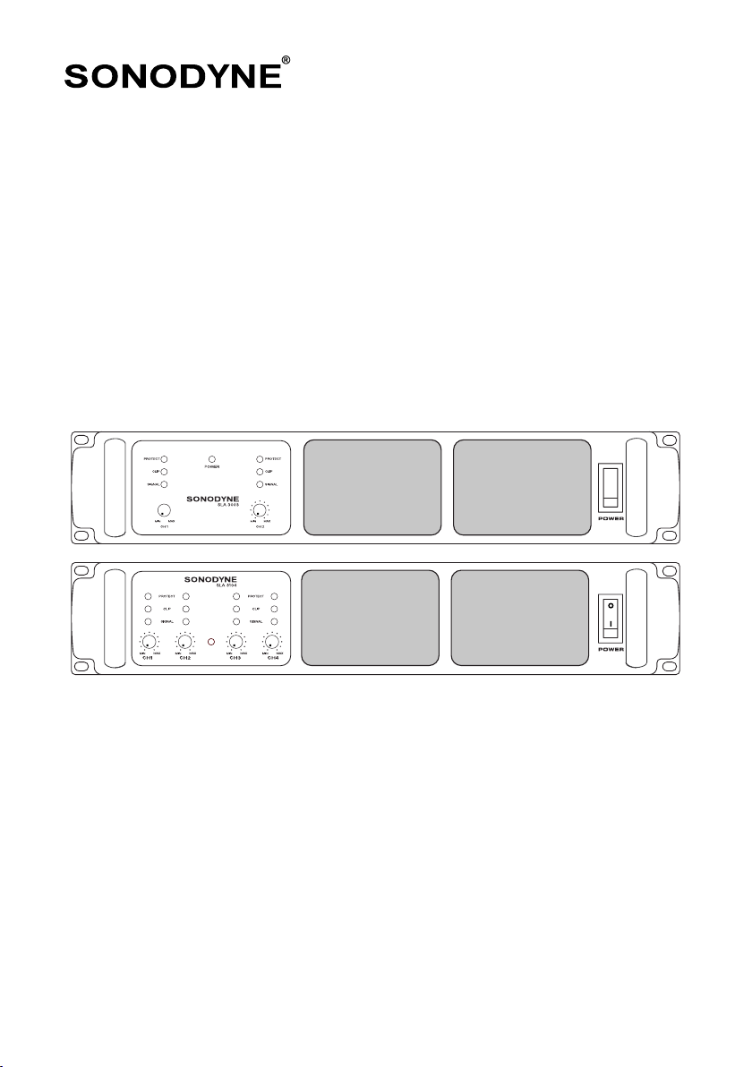
FRONT & TOP VIEWS
FRONT VIEW: SLA 3003/ 3004/ 3006/ 3008/ 3010/ 3013
FRONT VIEW: SLA 3104/ 3106
TOP VIEW
SLA SERIES page 6
445mm
430mm
NOTE: There should be
no blockage in the air
inlet and outlet

SLA SERIES page 7
FRONT PANEL
REAR PANEL
2
1 1 5
23 34 4
SLA 3003/ 3004/ 3006/ 3008/ 3010 3010/ 3013
SLA 3008/ 3010 3010/ 3013
SLA 3003/ 3004/ 3006
1. LEVEL CONTROLS:
Two calibrated and detent type potentiometers allow attenuation of signal levels.
2. PROTECT LED:
In the event of overload, DC at output, or overheat, the power amplifier is muted to protect the unit and
the LED turns on.
3. CLIP LED:
Lights up when the output stage starts to clip. Always set level so that this LED lights up only at peaks,
to prevent damage to speaker from excessive clipping.
4. SIGNAL LED
Lights up at 1W output power
5. POWER SWITCH
Rocker type switch to turn the amplifier on or off.
1 12
2 1 3 6 7 9
2
2 1 5 6 7 8
3 4 5 6 6 7 7 9810
4

SLA SERIES page 8
REAR PANEL
SLA 3003/ 3004/ 3006/ 3008/ 3010 3010/ 3013
1. INPUT
There are two such sockets, for Channel 1 and Channel 2. These are balanced XLR type input, for both
Channel 1 and Channel 2, having pin connections as per IEC60268 standard, printed on the back plate
and are as follows pin 1: ground, pin 2: hot (+), and pin 3: cold (-). The impedance in balanced mode is
20kΩ.
2. LINK
There are two such sockets, for Channel 1 and Channel 2. These are connected in parallel to the
respective input
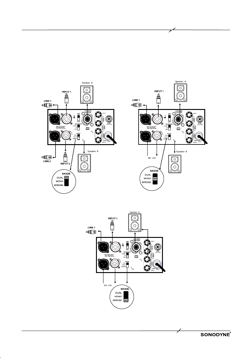
3. MODE SWITCH
This selects between 3 types of operation – Dual, Mono and Bridge. Please see Fig 1.
• Dual mode – 2 inputs, 2 outputs. Signal is applied to all four channels and outputs are taken from
all four channels.
• Mono mode - 1 input, 2 outputs. Input channels 1 is active only. Signal applied to channel 1 appears
at output of Channels 1 and 2.
• Bridge mode – 1 input, 1 output. In bridge mode the outputs of two channels are combined to
deliver higher power into a single speaker load. Input channel 1 is active only. For signal applied
to channel 1, outputs of channels 1 and 2 are combined to have a single output at the socket
marked Dual/Bridge corresponding to Channel 1, or across the positive terminals of binding posts of
Channels 1 and 2, as shown on the back plate
4. SENSITIVITY SWITCH
Use this to select input sensitivity between 0.775V, 1.0V and 1.4V.
5. GROUND LIFT SWITCH
This disconnects the input socket ground from the chassis ground, in gnd-lift mode. It is sometimes
required to solve ground related problems in certain applications.
6. TWIST-LOCK SPEAKER SOCKETS
There are two such sockets, for Channel 1 and Channel 2. Pin connections for dual or mono mode are
shown in the back plate and are as follows - pin 1+ positive and pin1- negative, for both channels. For
bridge mode, output is taken from Channel 1 only and pin connections are as follows - pin 1+ positive
and pin 2+ negative.
7. BINDING POSTS.
There are a pair of binding posts, for Channel 1 and Channel 2. For dual or mono mode, the red terminal
is positive, and the black negative, for both channels. For bridge mode, the output is taken from the
positive terminal of each channel, as shown in the back plate. The red terminal of Channel is positive,
and the red terminal of Channel 2 is negative
8. FUSE
This is a safety device to protect against misuse and resulting fire hazards. To replace fuse unscrew and
remove the burnt fuse. Use only the correct type of fuse for replacement. This is a slow-blow or time-
delay type fuse. The fuse rating is marked on the back-panel.
9. MAINS CABLE
This is a 3 pin mains cable with 15A plug. Connect this to an earthed 15A mains utility socket

SLA SERIES page 9
OPERATION
SLA 3003/ 3004/ 3006/ 3008/ 3010 3010/ 3013
4.1 POWER SUPPLY REQUIREMENTS
Each amplifier has a different output power rating, please refer to the printing on rear panel. Make sure
the supply voltage is correct before connecting the amplifier. Connecting the amplifier to a mismatched
AC voltage can cause damage to the amplifier.
The power supply requirement is: 230VAC/50 Hz
4.2 COOLING SYSTEM AND REQUIREMENTS
The amplifier uses forced air cooling. Cool air is sucked in through two ventilation pockets on front
panel by fans mounted in the heat tunnel. This cools the heat sink. The "intelligent" variable speed
DC fan is controlled by a thermal circuit which senses the temperature of the heat sink. When the
amplifier is turned on, the fan speed increases for a short time and then slows down; this indicates
that the thermal circuit is working properly. The fan speed will vary with the heat sink temperature. At
full power, the fan switches to high speed to cool the heat sinks. If the heat sink temperature exceeds
the maximum allowable temperature, the amplifier will shut down.
NOTE: To ensure optimum cooling conditions, check that the front and rear of the amplifier is
unobstructed and allows free flow of air.
4.3 INPUT CONNECTION
Connect the balanced output of your source equipment to this input with a 3 pin XLR female to XLR
male cable. For details please refer to the section on back panel above. To loop the input to a second
amplifier, connect the input of the second amplifier to the LINK terminal.
4.4 OUTPUT CONNECTION
The speakers are connected using either binding posts or twist-lock type sockets. For details
please refer to the section on back panel above

SLA SERIES page 10
MODE SWITCH SETTING DIAGRAMS
SLA 3003/ 3004/ 3006
MODE SWITCH DUAL
MODE SWITCH MONO
MODE SWITCH BRIDGE
SLA SERIES page 11
MODE SWITCH SETTING DIAGRAMS
SLA 3008/ 3010/ 3013
MODE SWITCH
DUAL
MODE SWITCH
MONO
MODE SWITCH
BRIDGE

SLA SERIES page 12
PIN CONNECTION DIAGRAMS
1. XLR SOCKET
BALANCED SOCKET
INPUT
LINK
PIN1=GND
PIN2=HOT
PIN3=COLD
UNBALANCED SOCKET
INPUT
LINK
PIN1=GND
PIN2=HOT
PIN3=COLD
2. TWIST-LOCK SPEAKER CONNECTORS
TWIST-LOCK CONNECTOR WIRING
3. TWO-WAY BINDING POST CONNECTORS
DUAL/MONO BRIDGE
4. GROUNDING
Mode Switch (GROUNDING)
SLA 3003/ 3004/ 3006/ 3008/ 3010 3010/ 3013
DUAL/MONO/PARALLEL Speaker
Speaker BRIDGE Speaker
Speaker
= 1+
= 1-
= 1+
= 2-

SLA SERIES page 13
FRONT PANEL
REAR PANEL
2 222
1 1 1 1 5
3 333 4 444
SLA 3104/3106
1. LEVEL CONTROLS:
Four calibrated and detent type potentiometers allow attenuation of signal levels
2. SIGNAL LED
Lights up at 1W output power
3. CLIP LED:
Lights up when the output stage starts to clip. Always set level so that this LED lights up only at peaks,
to prevent damage to speaker from excessive clipping.
4. PROTECT LED:
In the event of overload, DC at output, or overheat, the power amplifier is muted to protect the unit and
the LED turns on.
5. POWER SWITCH
Rocker type switch to turn the amplifier on or off.
6 6 6 6
7 7 7 79
8 8
11 10 12
9

SLA 3104/3106
SLA SERIES page 14
REAR PANEL
6. INPUT
There are four such sockets - Channel 1, Channel 2, Channel 3 and Channel 4. These are balanced
XLR type inputs, having pin connections as per IEC60268 standard, printed on the back plate and are
as follows pin 1: ground, pin 2: hot (+), and pin 3: cold (-). The impedance in balanced mode is 20kΩ
7. TWIST-LOCK SPEAKER SOCKETS
There are four such sockets - Channel 1, Channel 2, Channel 3 and Channel 4. Pin connections for
dual or mono mode are as follows - pin 1+ positive and pin1- negative, for all four channels. For
bridge mode, output is taken from the channels marked Dual/Bridge corresponding to Channels 2 and
4. Pin connections are as follows - pin 1+ positive and pin 2+ negative. For dual/mono/bridge mode
operation, please see under #8
8. MODE SWITCH
This selects between 3 types of operation – Dual, Mono and Bridge. Please see Fig 1.
• Dual mode – 4 inputs, 4 outputs. Signal is applied to all four channels and outputs are taken from
all four channels.
• Mono mode - 2 inputs, 4 outputs. Input channels 2 and 4 are active only. Signal applied to
channel 2 appears at output of Channels 1 and 2. Similarly, signal applied to channel 4 appears
at output of Channels 3 and 4.
• Bridge mode – 2 inputs, 2 outputs. In bridge mode the outputs of two channels are combined to
deliver higher power into a single speaker load. Input channels 2 and 4 are active only. For signal
applied to channel 2, outputs of channels 1 and 2 are combined to have a single output at the
socket marked Dual/Bridge corresponding to Channel 2. For signal applied to channel 4, outputs
of channels 3 and 4 are combined to have a single output at the socket marked Dual/ Bridge
corresponding to Channel 4
9. SENSITIVITY SWITCH
Use this to select input sensitivity between 0.775V, 1.0V and 1.4V.
10. GROUND LIFT SWITCH
This disconnects the input socket ground from the chassis ground, in ground-lift mode. It is required to
solve ground related hum and buzz problems in certain applications.
11. FUSE
This is a safety device to protect against misuse and resulting fire hazards. To replace fuse unscrew
and remove the burnt fuse. Use only the correct type of fuse for replacement. This is a slow-blow or
time-delay type fuse. The fuse rating is marked on the back-panel.
12. MAINS CABLE
This is a 3 pin mains cable with 15A plug. Connect this to an earthed 15A mains utility socket

SLA SERIES page 15
OPERATION
SLA 3104/3106
4.1 POWER SUPPLY REQUIREMENTS
Each amplifier has a different output power rating, please refer to the printing on rear panel. Make sure
the supply voltage is correct before connecting the amplifier. Connecting the amplifier to a mismatched
AC voltage can cause damage to the amplifier.
The power supply requirement is: 230VAC/50 Hz
4.2 COOLING SYSTEM AND REQUIREMENTS
The amplifier uses forced air cooling. Cool air is sucked in through two ventilation pockets on front
panel by fans mounted in the heat tunnel. This cools the heat sink. The "intelligent" variable speed
DC fan is controlled by a thermal circuit which senses the temperature of the heat sink. When the
amplifier is turned on, the fan speed increases for a short time and then slows down; this indicates that
the thermal circuit is working properly. The fan speed will vary with the heat sink temperature. At full
power, the fan switches to high speed to cool the heat sinks. If the heat sink temperature exceeds the
maximum allowable temperature, the amplifier will shut down.
NOTE: To ensure optimum cooling conditions, check that the front and rear of the amplifier is
unobstructed and allows free flow of air.
4.3 INPUT CONNECTION
Connect the balanced output of your source equipment to these inputs with a 3 pin XLR female to XLR
male cable. For details please refer to the section on back panel above
4.4 OUTPUT CONNECTION
The speakers are connected using twist-lock type sockets. For details please refer to the
section on back panel above.

SLA SERIES page 16
MODE SWITCH SETTING DIAGRAMS
MODE SWITCH
DUAL
MODE SWITCH
MONO
MODE SWITCH
BRIDGE
SLA 3104/3106

SLA SERIES page 17
SPECIFICATIONS
SLA 3003 SLA 3004 SLA 3006 SLA 3008
No. OF CHANNELS 2 2 2 2
OUTPUT POWER PER CHANNEL
8Ω
4Ω
8Ω BRIDGE
300W
450W
1000W
400W
600W
1200W
600W
900W
1800W
800W
1200W
2400W
THD @ RATED POWER 1% or less 1% or less 1% or less 1% or less
DAMPING FACTOR 300 280 250 240
SIGNAL TO NOISE RATIO
(20Hz~20kHz) 100dB 101dB 103dB 104dB
OUTPUT CIRCUITRY AB AB H H
FREQUENCY RESPONSE 20Hz~20kHz, ±0.5dB 20Hz~20kHz, ±0.5dB 20Hz~20kHz, ±0.5dB 20Hz~20kHz, ±0.5dB
INPUT CONNECTORS
EACH CHANNEL XLR with link XLR with link XLR with link XLR with link
OUTPUT CONNECTORS
EACH CHANNEL
Twist-lock connector
and binding post
Twist-lock connector
and binding post
Twist-lock connector
and binding post
Twist-lock connector and
binding post
AMPLIFIER AND
LOAD PROTECTION
Short circuit, output
DC, thermal, RF
protection
Short circuit, output
DC, thermal, RF
protection
Short circuit, output DC,
thermal, RF protection
Short circuit, output DC,
thermal, RF protection
FRONT PANEL CONTROLS
AND INDICATORS
Clip, Protect and
Signal LED indicators,
42 detent rotary vol
control
Clip, Protect and
Signal LED indicators,
42 detent rotary vol
control
Clip, Protect and Signal
LED indicators, 42
detent rotary vol control
Clip, Protect and Signal
LED indicators, 42
detent rotary vol control
REAR PANEL CONTROLS
3 position Slide switch
for Mode - Dual,
Mono, Bridge. 3
position Slide switch for
Sensitivity – 0.775V, 1
V and 1.4V.
3 position Slide switch
for Mode - Dual,
Mono, Bridge. 3
position Slide switch for
Sensitivity – 0.775V, 1
V and 1.4V.
3 position Slide switch
for Mode - Dual, Mono,
Bridge. 3 position Slide
switch for Sensitivity –
0.775V, 1 V and 1.4V.
3 position Slide switch
for Mode - Dual, Mono,
Bridge. 3 position Slide
switch for Sensitivity –
0.775V, 1 V and 1.4V.
INPUT POWER
(as per BIS IS616:2017
IEC60065:2014/IEC62368-1
600W 700W 550W 600W
DIMENSIONS (WxDxH) mm 461 x 482 x 94 461 x 482 x 94 461 x 482 x 94 461 x 482 x 94
WEIGHT 17 17.5 18.5 19
AGENCY APPROVALS
CE, BIS IS616:2017
IEC60065:2014/
IEC62368-1
CE, BIS IS616:2017
IEC60065:2014/
IEC62368-1
CE, BIS IS616:2017
IEC60065:2014/
IEC62368-1
CE, BIS IS616:2017
IEC60065:2014/
IEC62368-1
Due to continuous improvements, all specifications are subject to change
SPECIFICATIONS
SLA SERIES page 18
SLA 3010 SLA 3013
No. OF CHANNELS 2 2
OUTPUT POWER PER CHANNEL
8Ω
4Ω
8Ω BRIDGE
1000W
1400W
2800W
1350W
2150W
2700W
THD @ RATED POWER 1% or less 1% or less
DAMPING FACTOR 240 240
SIGNAL TO NOISE RATIO
(20Hz~20kHz) 105dB 105dB
OUTPUT CIRCUITRY H TD
FREQUENCY RESPONSE 20Hz~20kHz, ±0.5dB 20Hz~20kHz, ±0.5dB
INPUT CONNECTORS
EACH CHANNEL XLR with link XLR with link
OUTPUT CONNECTORS
EACH CHANNEL Twist-lock connector and binding post Twist-lock connector and binding post
AMPLIFIER AND
LOAD PROTECTION
Short circuit, output DC, thermal, RF protection Short circuit, output DC, thermal, RF protection
FRONT PANEL CONTROLS
AND INDICATORS
Clip, Protect and Signal LED indicators, 42 detent
rotary vol control
Clip, Protect and Signal LED indicators, 42 detent
rotary vol control
REAR PANEL CONTROLS
3 position Slide switch for Mode - Dual, Mono,
Bridge. 3 position Slide switch for Sensitivity –
0.775V, 1 V and 1.4V.
3 position Slide switch for Mode - Dual, Mono,
Bridge. 3 position Slide switch for Sensitivity –
0.775V, 1 V and 1.4V.
INPUT POWER
(as per BIS IS616:2017
IEC60065:2014/IEC62368-1
660W 730W
DIMENSIONS (WxDxH) mm 396 x 482 x 94 396 x 482 x 94
WEIGHT 20.5 21
AGENCY APPROVALS CE, BIS IS616:2017 IEC60065:2014/
IEC62368-1
CE, BIS IS616:2017 IEC60065:2014/
IEC62368-1
Due to continuous improvements, all specifications are subject to change
Due to continuous improvements, all specifications are subject to change
SPECIFICATIONS
SLA 3104 SLA 3106
No. OF CHANNELS 4 4
OUTPUT POWER PER CHANNEL
8Ω
4Ω
8Ω BRIDGE
400W
600W
1200W
600W
900W
1800W
THD @ RATED POWER 1% or less 1% or less
DAMPING FACTOR 280 250
SIGNAL TO NOISE RATIO
(20Hz~20kHz) 105dB 105dB
OUTPUT CIRCUITRY AB H
FREQUENCY RESPONSE 20Hz~20kHz, ±0.5dB 20Hz~20kHz, ±0.5dB
INPUT CONNECTORS
EACH CHANNEL XLR with link XLR with link
OUTPUT CONNECTORS
EACH CHANNEL Twist-lock connector and binding post Twist-lock connector and binding post
AMPLIFIER AND
LOAD PROTECTION
Short circuit, output DC, thermal, RF protection Short circuit, output DC, thermal, RF protection
FRONT PANEL CONTROLS
AND INDICATORS
Clip, Protect and Signal LED indicators, 42 detent
rotary vol control
Clip, Protect and Signal LED indicators, 42 detent
rotary vol control
REAR PANEL CONTROLS
3 position Slide switch for Mode - Dual, Mono,
Bridge. 3 position Slide switch for Sensitivity –
0.775V, 1 V and 1.4V.
3 position Slide switch for Mode - Dual, Mono,
Bridge. 3 position Slide switch for Sensitivity –
0.775V, 1 V and 1.4V.
INPUT POWER
(as per BIS IS616:2017
IEC60065:2014/IEC62368-1)
900W 800W
DIMENSIONS (WxDxH) mm 446 x 482 x 94 446 x 482 x 94
WEIGHT 20 22
AGENCY APPROVALS CE, BIS IS616:2017 IEC60065:2014/
IEC62368-1
CE, BIS IS616:2017 IEC60065:2014/
IEC62368-1
SONODYNE, India •H.O.: 98 NB Block E New Alipore, Kolkata 700053
sonodyneofficial SonodyneMusic sonodyneofficial
This manual suits for next models
10
Table of contents
Other Sonodyne Amplifier manuals


Popular Amplifier manuals by other brands


Boss Audio Systems
Boss Audio Systems RGD2400 user manual

A.H. Systems
A.H. Systems PAM-0118 Operation manual

Cary Audio Design
Cary Audio Design SA-500.1 owner's manual

Alpine
Alpine PDX-M6 Service manual

Plinius
Plinius SA-103 instruction manual

Studiomaster Professional
Studiomaster Professional XPA 40 instruction manual


