Sonodyne SVM Series User manual

SVM SERIES
SVM WDH1 I SVM WLH1
professional wireless microphone systems I owners manual
www.sonodyne.com

SVM SERIES page 1
STATUTORY INFORMATION/ CLEANING
CHECKLIST
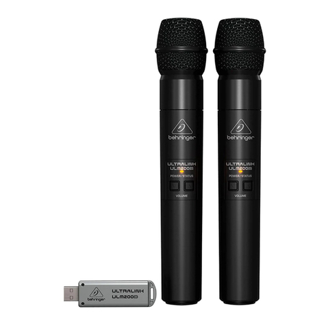
Please check that the following are included:
RECEIVER HAND-
HELD MIC
SET OF
LAPEL MIC
POWER
ADAPTER
CABLE
TRS-TRS
AA
BATTERY
OWNERS
MANUAL
SVM WDH1 1 2 - 1 1 2 1
SVM WLH1 1 1 1 1 1 2 1
IMPORTANT: The lapel mic set consists of one body-pack transmitter, one lapel mic and one headset mic.
Be sure to retain the original packing incase re-shipping is required.
NOTE:
1. Do not open the receiver or try to repair the product yourself. No user-serviceable parts inside
2. Unplug the adapter from the mains when not in use for a long time
3. Do not charge the batteries
CLEANING
Please make sure the power is disconnected before cleaning or repairing the receiver
The receiver can be cleaned by using a soft cloth with water. Dry the receiver with a dry cloth and let it air
dry for 15 minutes
Please do not use volatile gasoline, diluents or other chemicals to clean the receiver as this will damage the
surface

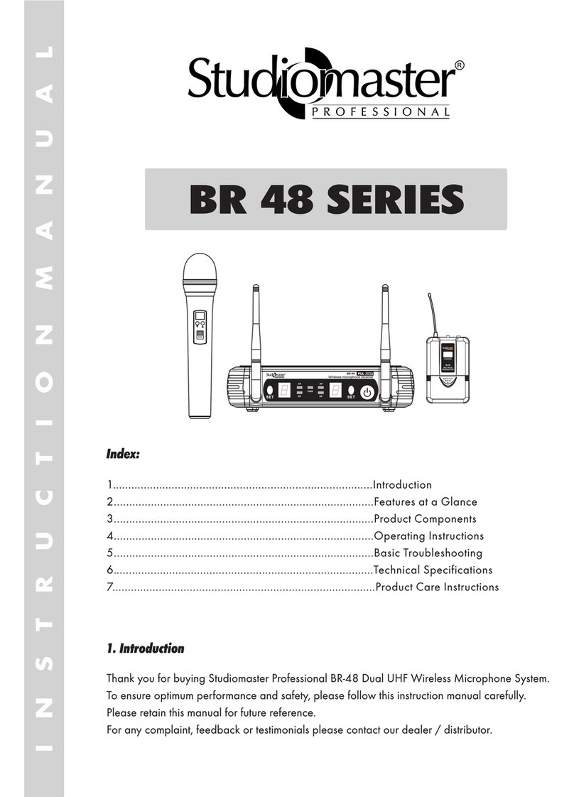
RECEIVER FRONT PANEL
1. POWER SWITCH: Press this switch to turn the unit on or off
2. DISPLAY PANEL: This shows the channel no. and the transmitting frequency
3. VOLUME CONTROL: There are 2 volume controls - one for CH-A and one for CH-B
4. AF: This lights up when the microphone receives signal. One is for CH-A and one is for CH-B
5. RF: This lights up when the microphone is switched on. One is for CH-A and the other for CH-B
RECEIVER REAR PANEL
6. ANTENNA
7. BALANCED AUDIO OUTPUT for CH-A and CH-B
8. UNBALANCED MIX OUT
9. DC INPUT JACK: 12V DC
SVM SERIES page 2
RECEIVER FRONT & REAR PANEL
2
34
5
1
6 7 8 97 6

TRANSMITTERS
SVM SERIES page 3
10. LCD DISPLAY - Displays transmitting frequency
11. POWER SWITCH - Slide up to switch on, slide down to switch off
12. ANTENNA
13. POWER SWITCH: Press the button for 2-3 seconds to turn on, the LED lights up. Press the
button again for 2-3 seconds to turn off
14. 3.5mm PHONE JACK for MIC
15. LED INDICATOR: Lights up when turned on. Flashes in low battery condition
16. LCD DISPLAY: Displays transmitting frequency
17. BATTERY STORE COMPARTMENT
18. BATTERY COVER
12
13 14
11
17
10
15
16
17
18

INSTALLATION
SVM SERIES page 4
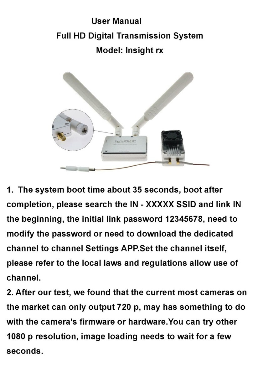
1. Connect receiver to 12V 1000mA DC adapter
2. Connect one end of a 1/4” TRS to TRS cable to the receiver’s UNBALANCED AUDIO OUTPUT (MIX) and
the other end to a mixer or power amplifier. If you are using the BALANCED AUDIO OUTPUT use an XLR
cable or XLR to 1/4” TRS cable
3. Unscrew the cover handle of the microphone counter-clockwise to check to see if there are batteries. If
not, put the batteries in the microphones in the correct polarity.
BALANCED
OUTPUT - B
UNBALANCED
OUTPUT
BALANCED
OUTPUT - A
POWER OUTLET
POWER ADAPTER
CH. B
TO POWER AMP/MIXER
CH. A
1/4" to 1/4" cable
12V power adapter cable

TROUBLESHOOTING
SVM SERIES page 5
If you are having operating problems or suspect somethings wrong with the unit, please check the
troubleshooting list below to see if the issue is a result of incorrect operation rather than equipment
malfunction
PROBLEM: Receiver: No sound, no lights
POSSIBLE CAUSE: • PowerButtonisoff
• DCpoweradapternotpluggedin
• PoorconnectionofDCpoweradapter
SOLUTION: • Turnonthepowerbutton
• PlugintheDCpoweradapter
• ChecktoseeiftheDCpoweradapterisloose
PROBLEM: Microphone: No sound, lights on
POSSIBLE CAUSE: • Thetransmitterisoutofrange
• Microphoneswitchisofformuted
• Microphonevolumeisturneddown
• Batteriesinthemicrophonenotinstalledproperly
• Theantennaisnotfullyfunctional
• Receiverisnotconnectedtoanamplierormixer
SOLUTION: • Operatetheunitintheeffectiverange
• Turnonthemicrophoneswitch(indicatedbygreenlight)
• Turnonthemicrophonevolumeonthereceiver
• Reinstallthebatteries.Makesurethepositiveandnegativeendsare
installed correctly
• Trytochangetheangleoftheantenna
• Connectthephonejackcablefromthereceivertoamicrophoneinput
(mixer, player etc). See page 4 for details
PROBLEM: Distorted sound, feedback
POSSIBLE CAUSE: • The2microphonesaretooclosetogether
• Batteriesrunninglowinmicrophones
• Microphonevolumeistoohigh
SOLUTION: • Separatethemicrophonesfurtherapart
• Replacethebatteries
• Reducethevolumeofthemicrophone
• Movethereceiverawayfromelectricequipments

FEATURES & SPECIFICATIONS
Due to continuous improvements, all specifications are subject to change
SVM SERIES page 6
FEATURES
Two high sensitivity microphones with LCD indicators
Noise reduction technology
Applicable for medium and small stages and home entertainment etc.
SPECIFICATIONS
RECEIVER
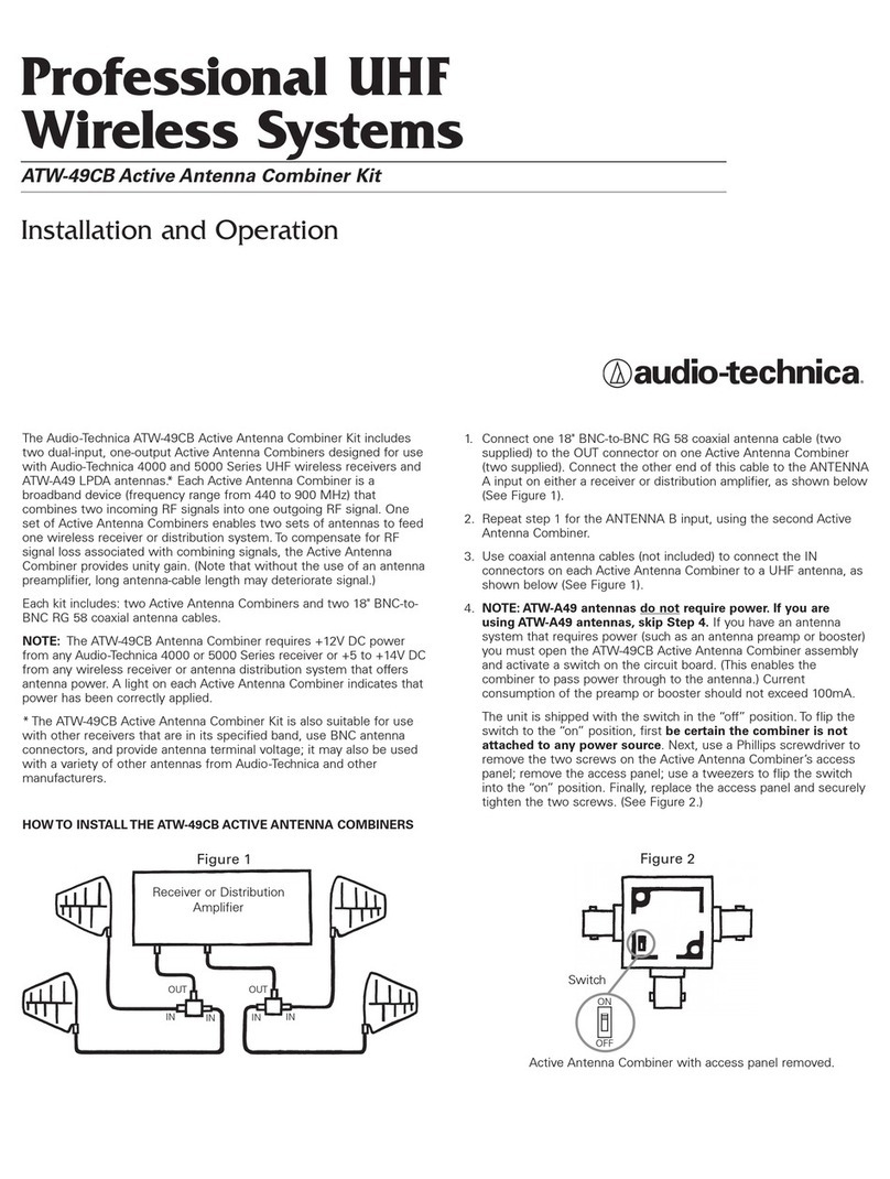
FREQUENCY RANGE: UHF 520-580MHz, 615-675MHz
SENSITIVITY: -105dB @ sinad= 12dB
S/N RATIO: >105dB
THD: <0.5% @ 1kHz
IMAGE REJECTION: 85dB typical
SPURIOUS REJECTION: 75dB typical
FREQUENCY RESPONSE: 40Hz ~ 18kHz
WORKING DISTANCE: >200 ft
AF OUTPUT IMPEDANCE: 2.2kOhm
MAX. OUTPUT LEVEL: Balanced 0~400mV, Unbalanced 0~200mV
DISPLAY: LCD
POWER SUPPLY: External DC power supply, 1A, 12V DC
OUTPUT CONNECTOR: XLR balanced socket, Unbalanced TRS 6.35mm socket
TRANSMITTER
TRANSMITTER POWER: 30mW
SPURIOUS EMISSION: <40dB (with carrier)
DISPLAY: LCD
BATTERY VOLTAGE: 1.5V x 2 pcs
BATTERY LIFE: 6-8 hours

AproductoftheMukherjeeInnovationCentre
Sonodyne Technologies Pvt. Ltd, 98 NB Block E New Alipore, Kolkata 700053, INDIA
Please visit us at www.sonodyne.com
This manual suits for next models
2
Table of contents