Sontay SD-521 User manual
UK Sales Tel: 0845 345 7253 International Tel: +44 1732 861225
Duct Smoke Detector
Page 1 of 3
SD-521
Issue: 5.8
Date Of Issue: 02/06/2010
© 2010 Sontay Limited. All rights reserved.
Features
Specification Product Codes
• Damped or un-damped output
• Manual or auto reset
• Analogue output for service diagnostics
Supply 24Vac 50/60Hz or 24Vdc(-10 +15%)
Power consumption 62mA
Outputs:
Relay SPST 1A @ 24Vdc, 120Vac
Analogue 2-10Vdc
Analogue status levels:
<2Vdc Sensor fault
3-7Vdc Normal operation
7-9Vdc Optics require cleaning
>9.5Vdc Smoke alarm
Minimum duct size 100 x 320mm
Maximum duct size 450 x 450mm
LED indication ON in alarm
Reset Manual or auto reset, selectable
Sensitivity 3 to 25% obscuration, adjustable
Signal damping On/Off selectable
Housing:
Dimensions 130 x 68 x 58mm
Material Glass-filled Polycarbonate to
UL94V-0
Probe:
Dimensions 300 x 25.5mm dia.
Material ABS plastic
Protection IP65 (housing only)
Ambient range:
Temperature +10 to 40°C
RH 0 to 95% non-condensing
Country of origin UK
SD-521
Duct smoke detector, 300mm probe

Page 2 of 3
UK Sales Tel: 0845 345 7253 International Tel: +44 1732 861225
SD-521
Issue: 5.8
Date Of Issue: 02/06/2010
© 2010 Sontay Limited. All rights reserved.
Technical Overview Recommendations (continued)
The SD-521 provides an auto or manual reset relay output
on detection of smoke, with a user adjustable threshold. An
analogue output can transmit smoke and service alarms to a
BEMS system.
Description
The SD-521 duct smoke detector has been developed from a
proven design using modern devices to provide effective and
reliable detection of smoke in ventilation systems.
Detection of smoke is achieved by monitoring a carefully
controlled infra red beam within a perforated tube which is
inserted into the ductwork. This method senses smoke
directly within the duct eliminating the problems associated
with conventional detectors mounted in sampling boxes.
Circuitry incorporated in the design of the detector controls
the infra red beam continuously. This ensures that the
detectors response will remain constant throughout
operation of the system. External influences including
background pollution, airborne dust and low level electrical
interference frequently found in commercial and industrial
applications, a common source of problems with some other
types of detector, are selectively filtered by the electronics
thereby providing the highest sensitivity to smoke combined
with effective rejection of short term disturbances that
would otherwise give a false alarm.
The detector features variable sensitivity and an advanced
signal damping circuit which can be bypassed for testing
purposes. And this signal is available as an analogue output
to communicate with a building management system.
Recommendations
The SD-521 has a probe length of 300mm and should NOT
be used in ducts with a diameter or square size greater than
450mm, as it will not monitor the whole of the duct and
smoke may pass along the duct without being detected.
Units should NOT be mounted where ambient sunlight will
fall on the photocell.
Units should never be mounted at or near sharp bends in
ductwork, as turbulence and side currents can carry the
smoke away from the probe.
The SD-521 is an optical beam detector and therefore, air
velocity has little effect on performance. However, careful
positioning of the detector is required if optimum detection
is to be achieved. The detector should always be fitted with
the holes in the sensing tube parallel to the airflow.
Units should to be mounted close to supply or extract fans.
With large installations, where several ducts collect into a
common duct, consideration must be given to dilution of
smoke and rate of airflow. For example, 10 small ducts may
feed at different points into one large main extract duct, and
if only one smoke detector is fitted in the main extract duct,
the position can arise where one duct is feeding smoke and
nine are feeding clean air. The amount of smoke is therefore
diluted by 90%, and if this is coupled with a high flow rate,
the smoke may not be detected for the minimum operating
period of 1 second, resulting in no alarm being generated. It
may be necessary to mount 10 detectors in each of the
small ducts to guarantee correct operation.
Installation Notes
Removable links are provided for signal damping and
internal latching of the output relay.
It is recommended that the damping be used (LK1) for
normal use as this will give the best false alarm rejection.
The link should be removed for testing purposes.
The internal latching circuit is enabled with the link LK2 in
place, in this condition any alarm will result in the detector
signal remaining on until locally reset. If the latching link is
removed and conditions return to normal for this reason the
electrical circuit to which the detector is connected should
have self latch with reset facilities.
Due to the self calibrating design of the detector as dust
builds up on the optics the internal signal is increased to
compensate, this results in the detector maintaining
sensitivity during operation. Failure to clean the detector will
ultimately result in an alarm signal occurring. At the final
signal level, either from dust accumulation or dense smoke
the detector will remain in alarm state for a minimum of 1
minute, following this final stage the detector will not be
able to recalibrate and will no longer function correctly.
As with all detectors it is not recommended to switch fan or
damper loads directly as any fire in the vicinity may damage
the detector or the wiring resulting in loss of control.
Whilst every effort has been made to ensure the accuracy of this specification, Sontay cannot accept responsibility for damage, injury, loss or
expense resulting from errors or omissions. In the interest of technical improvement, this specification may be altered without notice.
Page 3 of 3
UK Sales Tel: 0845 345 7253 International Tel: +44 1732 861225
For the latest information and product updates, register at www.sontay.com
SD-521
Issue: 5.8
Date Of Issue: 02/06/2010
© 2010 Sontay Limited. All rights reserved.
Installation
1. The SD-521 should only be installed by a competent,
suitably trained technician, experienced in installation
with hazardous voltages. (>50Vac & <1000Vac or
>75Vdc & 1500Vdc)
2. Ensure that all power is disconnected before carrying out
any work on the SD-521.
3. Maximum cable is 2.5mm², care must be taken not to
over tighten terminals.
4. If the sensor is mounted outside, it is recommended
that the unit be mounted with the cable entry at the
bottom. If the cable is fed from above then into the
cable gland at the bottom, it is recommended that a rain
loop be placed in the cable before entry into the sensor.
5. Drill two holes at 142mm centres, and a 26mm dia.
probe hole as dimensions on page 3. Fix the IP65 hous-
ing to the duct with appropriate screws.
6. Remove the front cover by undoing the two screws on
the lid and separating from the main body.
7. Feed the cable through the waterproof gland and termi-
nate the cores at the terminal block. Leaving some slack
inside the unit, tighten the cable gland onto the cable to
ensure water tightness.
8. Replace the lid after the connections have been made.
9. Ensure the voltage is within the specified tolerances.
10. Allow 3 minutes before checking functionality.
11.Allow 30 minutes before any pre-commissioning checks.
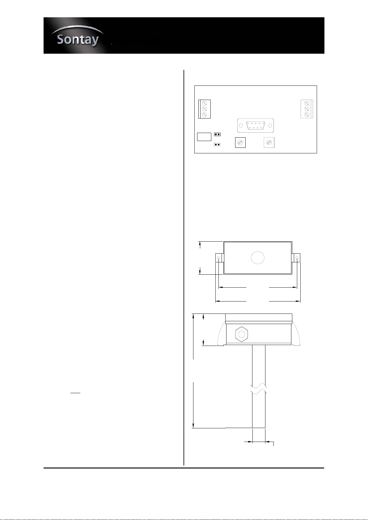
Connections
Links & adjustments: Terminals:
VR1 Do NOT adjust 1 - 0V
VR2 Sensitivity 2 - 24Vac/dc
LK1: 3 - 2-10Vdc Output
ON = Output damped 4- Relay common
OFF = Output un-damped 5 - Not used
LK2: 6 - Relay N/O
ON = Alarm manual reset
OFF = Alarm auto reset
Connections (continued)
Relay Mode
All units are supplied in manual-reset mode. To convert to
auto-reset mode, remove the link LK2. To revert back to
manual-reset replace the LK2 link.
To reset an alarm, or after power failure, press the RESET
button on the sensor lid.
Dimensions
6
5
4
1
2
3
LK1
LK2 VR2 VR1
160.9mm
148.9mm
67.0 mm
360.0mm
60.0mm
25.0 mm
Other Sontay Smoke Alarm manuals


