Bat
ee
a
Table
of
Contents
introduction
PROCAUNONS
5.
c2iscivsvasssssvestscovadosseedescestosvesivadedodcossoussuceaduseunsess
3
Getting
Started
UNPACKING
cisccissssssroscssconcctsevastesssstostesteseoedsonesstnonsessvncvassenooeas
Choosing
a
good
location
....
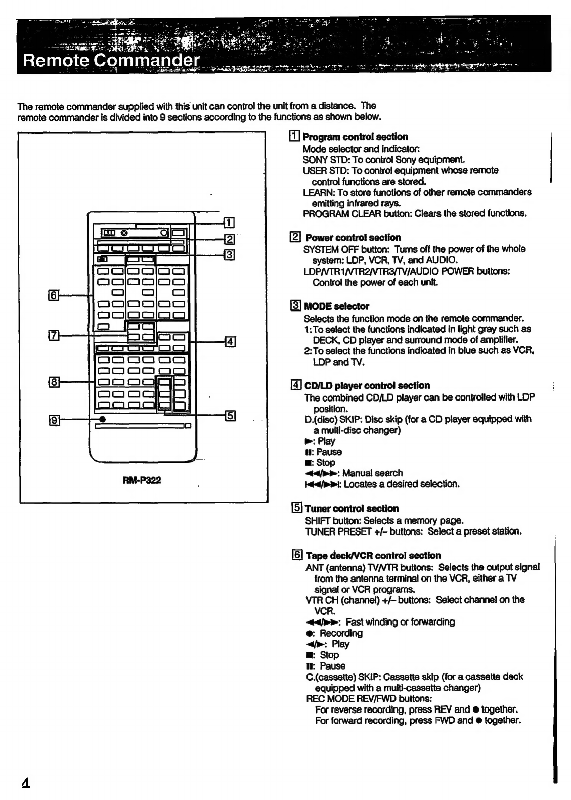
Remote
commander
..........s000
Hooking
Up
the
SYStCM
............ccssscrsercssenscesescrscserserscesenees
Connecting
audio
CQuIPMENE
...........cccscerscrscesesere
eatieets
6
Connecting
SP@aKers
........ccccsescccsseseressserscscsssssnesseseoees
7
Using
Your
Stereo
Getting
ready
to
enjoy
Surround
SOUNG
..............essecsccssrserees
8
Positioning
the
SPEAKETS
.......:scscesescsscessrsesesssessseescsenssnses
8
Placement
of
speakers
and
selecting
the
PRO
LOGIG
MODE
a
eisssscssicscssssasscscssnoesstesbecasssssccbestcdscastestacass
8
Adjusting
the
speaker
VoIUIMe
............cssccssecercsesssesessesenees
9
Adjusting
the
delay
time
of
the
rear
speakers
................
10
Adjusting
the
audio
Controls
............scsssssscssssssserssescserees
10
ACJUStING
VOIUME
.........ccccercsercssccrsecsressrscsesees
Senddaesvesessese
10
Adjusting
the
left
and
right
sound
balance
...............s000
10
Adjusting
the
tone
from
the
front
speaker
............seesees
10
Reinforcing
the
Dass
SOUNG
............csscrcseessesesssscrsessenes
10
Selecting
the
speaker
system.............
Suacesducvoszccecensaacensoes
10
Listening
to
&
Program
SOUICE
.........cccersessssessesssesecessees
11
Listening
with
the
surround
effect
............ccersrsscrsorscrsecsees
11
RECOFING
vvssscsscccsscsnrcccascrasscscdeccsesseseceisosasseessenssvessnsscsiccess
12
Storing
other
manufacturer's
operating
codes
onto
the
Supplied
remote
COMMANAET
............ccssccsssorsrcesecercsesosreees
13
Programming
signals
of
other
audio/video
equipment...
13
Programming
a
new
signal
onto
a
previously
PFOGTAMMEM
DUION
......s.sssesrsssseeseresesssseersesscsssssssssesees
14
Controlling
CQUIPMENE...........cssserstsrsrsrsesessesrsestsnseees
14
General
SPECIICALONS
5
aiid
ca
cssvssesiessassuseasussavevecbeasetbeacersensteceedsenvens
15
TrOUDIESHOOTING
..........cscerssrsorssrscessssscssrssessesses
Back
cover
Precautions
On
safety
©
Operate
the
unit
only
on
120
V
AC,
60
Hz.
©
Should
any
solid
object
or
liquid
fall
into
the
unit,
unplug
it
and
have
it
checked
by
qualified
personnel
before
operating
it
any
further.
e
Unplug
the
unit
from
the
wall
outlet
if
it
is
not
to
be
used
for
an
extended
period
of
time.
To
disconnect
the
cord,
pull
it
out
by
grasping
the
plug.
Never
pull
the
cord
itself.
On
operation
Before
making
program
source
connections,
be
sure
to
turn
the
power
switch
off
and
unplug
the
unit.
On
cleaning
the
cabinet
Clean
the
cabinet,
panel
and
controls
with
a
soft
cloth
lightly
moistened
with
mild
detergent
solution.
Do
not
use
any
type
of
abrasive
pad,
scouring
powder
or
solvent
such
as
alcohol
or
benzine.
For
detailed
safety
precautions,
see
the
leaflet
“IMPORTANT
SAFEGUARDS’.
If
you
have
any
question
or
problem
concerning
your
unit,
please
consult
your
nearest
Sony
dealer.
UT
al
ercter
diate
m
7
aToloy-)iale
m=
Crelole
ml
meoler-htloya]
To
prevent
internal
heat
buildup
in
the
unit,
place
the
unit
in
a
location
with
adequate
air
circulation.
Do
not
install
the
unit:
©
near
heat
sources
such
as
radiators
or
air
ducts.
¢
in
a
place
subject
to
direct
sunlight,
excessive
dust,
mechanical
vibration
or
shock.
Do
not
place
anything
on
top
of
the
cabinet.
The
top
ventilation
holes
must
be
unobstructed
for
the
proper
operation
of
the
unit
and
to
prolong
the
life
of
its
components.
Do
not
throw
away
the
carton
and
packing
material!
It
will
be
an
ideal
container
when
transporting
the
unit
for
repair
work.
etc.