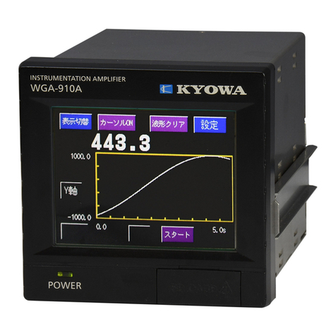
KYOWA WGA-910A Series User manual

IM-A-1142 July 2017
INSTRUCTION MANUAL
WGA-910A
INSTRUMENTATION AMPLIFIER
(FOR OPTIONS)
WGA-910A-1: BCD
WGA-910A-2: D/A
WGA-910A-3: RS-485
WGA-910A-12: BCD and D/A
Thank you for purchasing KYOWA’s product WGA-910A Instrumentation
Amplifier.
Read this Instruction Manual carefully in order to make full use of the high
performance capabilities of the product.
Do not use the product in methods other than described in this Manual.
Generally, company names and trade names described in this Instruction Manual are trademarks or registered
trademarks of the companies.
This Instruction Manual may not be copied or reproduced, in whole or part, without consent of KYOWA.
Copyright © Kyowa Electronic Instruments Co., Ltd. All rights reserved.
The contents of the Instruction Manual are subjected to change without prior notice.
Please follow the safety precautions and other precautions described in this manual.

1
CONTENTS
CONTENTS
1
STANDARD ACCESSORIES
1
OPTIONAL ACCESSORIES
1
SAFETY PRECAUTIONS
2
PRECAUTIONS ON CE MARKING
5
NOTATIONS USED IN THE INSTRUCTION MANUAL
6
IMPORTANT PRECAUTIONS WHEN USING WGA-910A AND OPTIONAL UNITS
6
1. BCD OUTPUT
7
1-1. OUTLINE OF PRODUCT
7
1-2. CONTROLS AND INDICATORS (REAR PANEL)
7
1-3. BCD OUTPUT SPECIFICATIONS
8
1-4. PIN NUMBERS AND SIGNAL NAMES
8
1-5. CONNECTING BCD OUTPUT
9
1-6. SETTING BCD OUTPUT
9
1-7. BCD SIGNAL TIMING
13
2. D/A OUTPUT
15
2-1. OUTLINE OF PRODUCT
15
2-2. CONTROLS AND INDICATORS (REAR PANEL)
15
2-3. D/A OUTPUT SPECIFICATIONS
16
2-4. TERMINAL NAMES AND SIGNAL NAMES
16
2-5. CONNECTING D/A OUTPUT
16
2-6. D/A OUTPUT SET
17
2-6-1. D/A Display
17
2-6-2. D/A Classification
18
3. RS-485 OPTIONS
19
3-1. OUTLINE OF PRODUCT
19
3-2. CONTROLS AND INDICATORS (REAR PANEL)
19
3-3. RS-485 SPECIFICATIONS
20
3-4. CONNECTOR PIN NUMBERS AND SIGNAL NAMES
20
3-5. CONNECTING TO EXTERNAL DEVICE
20
3-6. COMMUNICATION PROCEDURES
22
3-7. CONTROL COMMAND
23
3-7-1. Table of Control Commands
23
3-7-2. Details of Control Commands
23
3-8 OPERATION AND FUNCTION OF THE COM. SETTING
(
COMMUNICATION SETTING)
24
4. BCD and D/A OUTPUT SETTING
26
4-1. OUTLINE
26
4-2. CONTROLS AND INDICATORS (REAR PANEL)
26
4-3. BCD AND D/A OUTPUT SPECIFICATIONS
27
4-4. OUTLINE OF BCD / BINARY OUTPUT
28
4-5. PIN NUMBERS AND SIGNAL NAMES OF THE BCD OUTPUT TERMINAL
28
4-6. CONNECTING BCD OUTPUT
28
4-7. OUTLINE OF D/A OUTPUT
29
4-8. TERMINAL NAMES AND SIGNAL NAMES OF THE D/A OUTPUT TERMINAL
29
4-9. CONNECTING D/A OUTPUT
29
5. TROUBLE SHOOTING
30
5-1. OPERATION STOPS AND ACCEPTS NO INSTRUCTION AT ALL
30
5-2. THE BCD OUTPUT IS STABLE
30
5-3. THE D/A OUTPUT IS STABLE
30

2
6. MAINTENANCE
31
7. OUTSIDE DRAWING
32
7-1. WGA-910A-1: BCD OPTION
32
7-2. WGA-910A-2: D/A OPTION
33
7-3. WGA-910A-3: RS-485 OPTION
34
7-4. WGA-910A-12: BCD and D/A OPTION
35
8. APPENDIX
36
8-1. Option Setting
36

1
STANDARD ACCESSORIES
The following accessories are packed with the WGA-910A-1, WGA-910A-2, WGA-910A-3, WGA-910A-12.
When unpacking, check the contents to ensure that all accessories are enclosed.
Instruction Manual 1 (CD-R)
Test Certificate and Warranty 1 each
*1. Including a PC software for a SD card.
OPTIONAL ACCESSORIES
<BCD connector> (WGA-910A-1 BCD)
Connector Model: FCN-361J040-AU Manufacture: FUJITSU COMPONENT LIMITED
Cover Model: FCN-360C040-B Manufacture: FUJITSU COMPONENT LIMITED
<RS-485 connector> (WGA-910A-3 RS-485)
Connector Model: XM3D-0921 Manufacture: OMRON Corporation
Cover Model: XM2S-0913 Manufacture: OMRON Corporation
<BCD connector> (WGA-910A-12 BCD and D/A)
Connector Model: 10136-3000PE Manufacture: Sumitomo 3M Limited
Cover Model: 10336-52F0-008 Manufacture: Sumitomo 3M Limited

2
SAFETY PRECAUTIONS
The WGA-910A-1, WGA-910A-2, WGA-910A-3 and WGA-910A-12 are designed to be used according to "1-3.BCD
OUTPUT SPECIFICATIONS ", "2-3.D/A OUTPUT SPECIFICATIONS", "3-3, RS-485 SPECIFICATIONS ", and
"4-3.BCD and D/A OUTPUT SPECIFICATIONS ". Do not use the product in an environment exceeding the
specifications.
Or, it may cause troubles.
PRIOR TO USE
For safe use of the product, do not forget to read the “Safety Precautions” prior to use.
Kyowa Electronic Instruments Co., Ltd. assumes no liability for any damage resulting from the user's failure to comply
with the safety precautions.
For safety operation of the product, the following symbol marks are used in the Instruction Manual.
Indicates “PROTECTIVE GROUND TERMINAL.”
Be sure to connect the GND terminal to the ground.
SAFETY SYMBOLS
For safety operation of the product, the following symbol marks are used in the Instruction Manual.
WARNING
Improper operation of the system may result in death or severe injury of the operator.
CAUTION
Improper operation of the system may result in injury of the operator and physical
damage of the system.

3
WARNING
Warning
Be sure to observe the safety precautions described in the WGA-910A Instruction Manual.
Power Supply
To prevent a fire hazard, before connecting the power cable, be sure to check the local line voltage is matched
with the operating voltage specified for the WGA-910A.
The power supply voltage is described in following.
AC100 V
~
240 V 50/60 Hz Power consumption
:
20 VA or less
Power Cable and Power Outlet
To prevent an electric shock or fire hazard, connect a power cable and 3P-2P conversion adapter to a plug with
protective ground terminal.
When using 3P power cable, use a 3P power plug with protective ground terminal.
Operators must be cautioned that use of an extension power cable with no ground conductor disables the
protective ground function.
Check the Instruction Manual in advance, connect the power cable to the WGA-910A and connect the power
plug to an outlet.
Protective Ground
To prevent an electric shock hazard, be sure to ensure protective ground before connecting the power cable.
When using the 3P-2P conversion adapter, be sure to ground the grounding wire of the adapter to the GND
terminal.
When using a plastic 2P power cable, be sure to connect an optional grounding wire to the protective grounding
terminal.
For Electrical Operator Safety
To prevent an electric shock hazard, operators must be cautioned not to cut the protective grounding conductor or
disconnect the GND terminal.
Confirmation of Protective Ground
To prevent an electric shock hazard, be sure to check safe protective ground function before operating the
WGA-910A. If any abnormal matters are found in the protective ground function, fuse holder, etc., do not operate
the WGA-910A.
External Connection
To prevent an electric shock hazard, ensure the safe protective ground of all concerned instrument and then,
connect the WGA-910A to the measuring object and external devices, PC, etc.
Fuse
Used for preventing a fire hazard.
If you want to replace fuses, contact KYOWA or our representatives.
Inflammable Gaseous Environment
To prevent fire and explosion hazards, do not operate the WGA-910A where it is exposed to inflammable gases,
inflammable vapors or inflammable dust.
If Any Trouble Occurs
To prevent a fire hazard, if smoke is emitted from the WGA-910A, immediately disconnect the AC adaptor from
the receptacle and stop using the WGA-910A.
Maximum Input Voltage Range
The WGA-910A is a measuring instrument specified for strain gage transducers and strain gages. Do not input
high voltage. Or, deteriorated performance and damage of the product may result.
About built-in lithium battery
Do not short-circuit the battery terminals after disassembling. Or, it may cause an overheating and fire.
Never throw the battery into a fire or put it near a fire.
It may cause an overheating, fire, and explosion.
Do not charge the using battery since it is not rechargeable.
Or, it may explode.

4
CAUTION
Caution
Be sure to observe the safety precautions described in the WGA-910A Instruction Manual.
Do not use the product outdoors
Or, it may cause electric shock, fire hazard, lower the performance and cause troubles.
Do not turn ON the power switch immediately after turning it OFF
After turning OFF the power switch, wait (5 seconds) until the power supply is shut OFF before turning ON
the power switch again.
If the power is repeatedly turned ON and OFF within 5 seconds, rush current generated by switching the
power ON may damage the product.
Use the product within temperature ranging from -10 to +40
℃
Use at temperatures exceeding the specified range may lower the performance and cause trouble.
If use under direct sunlight or in a cold place is inevitable, prepare a sunscreen or take proper measures to keep it warm.
Use the product in the specified operating humidity of 20 to 85 % RH
Use in a humid place exceeding the specified range or where it is exposed to splashing water may lower the
performance and cause trouble.
Do not use the product immediately after the change in the environment
Leave the product as it is until it becomes adaptable to the environment.
Abrupt change in ambient temperature due to transportation, etc. may cause dew condensation, which may
result in lower performance and troubles.
Use the product under environment without excessive vibration or high impact
Vibration resistance: 19.6 m/s
2
(2 G), 10 to 200 Hz (when in operation)
Use the product in an area where vibration and impact can be kept within the scope of specifications.
Continuous vibration or severe impact may cause deteriorated performance and system failure.
Do not use the product in strong electromagnetic field
Use the product in a magnetic field environment where the PC may be used.
Performance may be lowered and erroneous operation and troubles may result if it is used near a telemetry
system, microwave oven, electronic furnace or any other equipment generating a strong magnetic field.
Do not use the product under poor conditions
Operate the product within the range of 100 to 240 VAC (50/60 Hz). The power supply used for the product
should not experience an instantaneous power failure and be free from noise.
Do not pull cords and cables
Lay cords and cables with a certain allowance so that unreasonable force is not applied to the connections.
Or, it may interrupt the measurements, break the cables, and damage the connectors.
Avoid installing sensors and products near a welding machine
Failure to do so will pose the risk of erroneous data, malfunction and failure.
Do not disassemble or remodel the product
Or, it may cause electric shock hazards or damage the product. This warranty does not cover any damaged or
defective parts that results from disassembling or remodeling.
Do not use or strage the product under dusty or fine particles or corrosive gas environment
Use or strage under these environment, may result in lower performance and troubles.
Do not expose the product to the air if it is used and stored nearby sea
Air exposure nearby sea may cause lower performance and products failure.
Take care when handling the CD-R
Do not expose the CD-R to direct sun light, high temperature, or high humidity.
Do not apply pressure to the CD-R by laying object or bending.
Dust, scratches, and fingerprints on either side of the CD-R can cause write errors.
Preheat the product before use
After the power ON, always preheat the product for approximately 30 minutes.
Cleaning
When the product gets dirty, clean the product with a dry soft cloth. When dust exists inside the
WGA-910A, clean it by using an air blow gun. Do not touch electronic parts.
5
When satisfying the following conditions, we evaluated the compatibility against the requirements of the EU
Directives and confirmed that the product satisfied the requirements.
To connect products, be sure to use the shielded D/A output cable, shielded BCD output cable and shielded
RS-485 cable. Wiring should be 30 m or less.
Before connecting the following cables, be sure to mount ferrite core near the terminal or connector.
・
D/A output cable
Recommended ferrite core E04SR301334 (SEIWA ELECTRIC MFG. CO., LTD.)
・
RS-485 cable
Recommended ferrite core E04SR301334 (SEIWA ELECTRIC MFG. CO., LTD.)
・
BCD output cable
Recommended ferrite core E04SR200932 (SEIWA ELECTRIC MFG. CO., LTD.)
Be sure to mount the product on the control panel, etc. Before turning ON the power, make sure the product is
covered to avoid contact with hands.
The product connection should be executed by experts in electrical work.
To immediately turn OFF the product, place switches or circuit breakers inside the building and near the product
and display the functions as well.
Use switches and circuit breakers conforming to the IEC60947-1 and IEC60947-3.
Use the product in area where elevation is 2000 m or below.
When mounting the product in your system, approaches to satisfy the CE marking requirements vary with the
configuration of the control panel to be used, the other devices to be connected, and wirings. Therefore,
customers are required to check whether the CE marking requirements on the product are satisfied or not.
Be sure to connect the protective grounding terminal to the ground by using the optional ground wire.
PRECAUTIONS ON CE MARKING
NOTE

6
The output signal (voltage/current) when the transducer cable is broken.
When the transducer cable is broken, the product may output the following output signal (voltage/current).
Therefore, take countermeasures to avoid the adverse effect, from the output signals, on the other measuring
instruments.
・
D/A output and BCD D/A output
Voltage output: Approx. 11.2 V
Current output: Approx. 22.1 mA
The output signal (voltage/current) and unbalance load
・
D/A output and BCD D/A output
Voltage output: The unbalance load should be 2k ohm or more.
Current output: The unbalance load should be 500 ohm or less.
The communication
・
RS-485
RS-232C communication is not availavel.
NOTATIONS USED IN THE INSTRUCTION MANUAL
The following notations are used in the Instruction Manual for convenience.
Names described on the panel surface
Names described on the panel surface are expressed in double quotation mark " ".
Informational notes
Certain notations are used as necessary to attract your attention to information that requires special care when
handing the product, and to information provided for reference purposes.
Examples of Notations
IMPORTANT PRECAUTIONS WHEN USING WGA-910A AND OPTIONAL UNITS
NOTE
Essential precautions required when handling the product.
NOTE
Reference items required when handling the product.
MEMO

7
Logic cannot be changed since the holding input and output prohibit input are fixed to the negative logic.
1. BCD OUTPUT
1-1. OUTLINE OF PRODUCT
The WGA-910A-1 is an instrumentation amplifier with the BCD option. These products are able to retrieve the
indicated values as the BCD data.
The product is able to control the PLC (sequencer), and be able to print data by using printers.
In addition, the input/output circuit is insulated from the WGA-910A circuit.
1-2. CONTROLS AND INDICATORS (REAR PANEL)
(1) BCD connector Retrieves the indicated values as the BCD data.
Controlled by using various input signals and output signals.
(1)
NOTE

8
The model and manufacture of connectors in BCD option is different from that of BCD connectors in BCD
and D/A option (Model: WGA-910A-12).
1-3. BCD OUTPUT SPECIFICATIONS
Output
.............................
BCD data: 20 bits (4-bit ×5-digit)
Binary data: 18 bits (offset binary)
Minus code: 1 bit
Over: 1 bit
EOC (End Of Conversion): 1 bit
Format: Open-collector
Max load capacity: 30 VDC, 20 mA (load resistance)
Input
...............................
Number of points: 2
Contents: Data hold input. … ……Negative logic (Hold at “L”)
Output prohibit input…..Negative logic (Prohibition at “L”)
Type: Open collector or Non-voltage contact signal
Voltage 12 VDC and current 5 mA can be applied.
Setting Contents
.............
Transmission speed: Approx. 16, 32, 64, 125, 250, 500, and 1000 times / sec.
Porality logic, EOC logic, Data logic: Negative or positive logic
Data form: BCD, Binary Changeable
BCD classification: Peak value, bottom value
1-4. PIN NUMBERS AND SIGNAL NAMES
Pin assignments of the BCD output are as follows.
Pin No. Signal Name Pin No. Signal Name
BCD Output Binary Output BCD Output Binary Output
A1 Data 1 Output Data 20(1) Output B1 Data 2 Output Data 21(2) Output
A2 Data 4 Output Data 22(3) Output B2 Data 8 Output Data 23(4) Output
A3 Data 10 Output Data 24(5) Output B3 Data 20 Output Data 25(6) Output
A4 Data 40 Output Data 26(7) Output B4 Data 80 Output Data 27(8) Output
A5 Data 100 Output Data 28(9) Output B5 Data 200 Output Data 29(10) Output
A6 Data 400 Output Data 2
10
(11)
Output
B6 Data 800 Output Data 2
11
(12)
Output
A7 Data 1000 Output Data 2
12
(13)
Output
B7 Data 2000 Output Data 2
13
(14)
Output
A8 Data 4000 Output Data 2
14
(15)
Output
B8 Data 8000 Output Data 2
15
(16)
Output
A9 Data 100000 Output Data 2
16
(17)
Output
B9 Data 20000 Output Data 2
17
(18)
Output
A10 Data 400000 Output Always OFF B10 Data 80000 Output Always OFF
A11 Minus (polarity) Output Always OFF B11 OVER
A12 EOC (End Of Conversion) Output B12 Holding Block Output
A13 Detecting Block Output B13 N.C
A14 N.C B14 N.C
A15 N.C B15 N.C
A16 N.C B16 N.C
A17 BCD Holding Input B17 BCD Output Prohibited Input
A18 COM B18 COM
A19 N.C B19 N.C
A20 N.C B20 N.C
(Note 1): Holding Block Output (Pin No. B12)
When in holding block: Open collector output is ON (Low).
(Note 2): Detecting Block Output (Pin No. A13)
When in detecting block: Open collector output is ON (Low).
NOTE

9
The model and manufacture of connectors in BCD option is different from that of BCD connectors in
BCD and D/A option (Model: WGA-910A-12).
Return Measure
Option Setting
'Communication Speed','Trans-
Com.Setting mission Mode'and 'Device ID'
of RS-232C/485 are set.
'Transmission Speed',logic of
BCD Output Setting each output,and 'BCD Classifi-
cation are set.
'Zero Dsp.'(0V) or 'Full Dsp.'
D/A Output Setting (10V),and 'D/A Classifica-
tion' are set.
'The Number of Occupied
CC-Link Setting Stations','Transmission Speed'
and 'Station Number' are set.
1 / 2Next
Return Measure
The logic of minus(polarity)
output is set.
Negative Logic
The transmission speed of BCD
data is set.
16times/sec
The logic of EOC(end of con-
version)output is set.
BCD Output Setting
Transmission Speed
EOC Logic
Negative Logic
Polarity Logic
The logic of data output(such
as 10)is set.
Negative Logic
Data Logic
Transmission Speed
Now
New 125times/sec
16times/sec
Return Measure
16times/sec 32times/sec
64times/sec 125times/sec
Register
Push the target key and 'Register'key.
1 / 2Next
Return Measure
The logic of minus(polarity)
output is set.
Negative Logic
The transmission speed of BCD
data is set.
16times/sec
The logic of EOC(end of con-
version)output is set.
BCD Output Setting
Transmission Speed
EOC Logic
Negative Logic
Polarity Logic
The logic of data output(such
as 10)is set.
Negative Logic
Data Logic
1-5. CONNECTING BCD OUTPUT
Applicable connectors of the cable side are as follows when connecting the external device.
Applicable connector
Connector Model: FCN-361J040-AU Manufacture: FUJITSU COMPONENT LIMITED
Cover Model: FCN-360C040-B Manufacture: FUJITSU COMPONENT LIMITED
1-6. SETTING BCD OUTPUT
(1) Transmission Speed
Sets the transmission speed of the BCD data output.
<Setting Range>
Approx. 16, 32, 64, 125, 250, 500, 1000 times/sec.
<How to operate>
1) Press the key on the “
Option Setting
” window.
2) Press the key on the “
BCD Output Setting(1/2)
”
window.
3) Press the target key and key to register the target value.
(2) EOC Logic
Sets the logic of the EOC (end of conversion) output.
For the negative logic, the open collector output of the BCD output terminal is ON, for the positive logic, the output
is OFF.
<Setting Range>
Negative logic / Positive logic
<How to operate>
1) Press the key on the “
BCD Output Setting(1/2)
”
window.
NOTE

10
Negative Logic
(open-collector output:OFF)
Now
Negativ Logic New
Positive Logic
Register
Return Measure
Push the target key and 'Register'key.
EOC Output Logic
Positive Logic
For EOC output logic:negative
(open-collector output:ON)
For EOC output logic:positive
1 / 2Next
Return Measure
The logic of minus(polarity)
output is set.
Negative Logic
The transmission speed of BCD
data is set.
16times/sec
The logic of EOC(end of con-
version)output is set.
BCD Output Setting
Transmission Speed
EOC Logic
Negative Logic
Polarity Logic
The logic of data output(such
as 10)is set.
Negative Logic
Data Logic
Polarity Logic
Positive Logic
Return Measure
Now
New
Negativ Logic
Register
Negative Logic
Positive Logic
OFF)
Push the target key and 'Register'key.
For minus output logic:nega-
tive(open-collector output:ON)
For minus output logic:posi-
tive(open-collector output:
1 / 2Next
Return Measure
The logic of minus(polarity)
output is set.
Negative Logic
The transmission speed of BCD
data is set.
16times/sec
The logic of EOC(end of con-
version)output is set.
BCD Output Setting
Transmission Speed
EOC Logic
Negative Logic
Polarity Logic
The logic of data output(such
as 10)is set.
Negative Logic
Data Logic
Data Logic
Positive Logic
Return Measure
Now
New
Negativ Logic
Register
Negative Logic
Positive Logic
Push the target key and 'Register'key.
For data output logic:negative
(open-collector output:ON)
For data output logic:positive
(open-collector output:OFF)
2) Press the target key and key to register the target value.
(3) Polarity Logic
Sets the logic of the minus (polarity) output.
<Setting Range>
Negative logic / Positive logic
<How to operate>
1) Press the key on the “
BCD Output Setting(1/2)
”
window.
2) Press the target key and key to register the target value.
(4) Data Logic
Sets the logic of the data output (10 etc).
<Setting Range>
Negative logic / Positive logic
<How to operate>
1) Press the key on the “
BCD Output Setting(1/2)
”
window.
2) Press the target key and key to register the target value.

11
The type of outputted binary data is offset binary.
1 / 2Next
Return Measure
The logic of minus(polarity)
output is set.
Negative Logic
The transmission speed of BCD
data is set.
16times/sec
The logic of EOC(end of con-
version)output is set.
BCD Output Setting
Transmission Speed
EOC Logic
Negative Logic
Polarity Logic
The logic of data output(such
as 10)is set.
Negative Logic
Data Logic
2 / 2Previous
Select data to output to BCD
BCD Classification output.
Peak Value
Return Measure
BCD Output Setting
The form of outputted data is
Data Form changed to BCD or binary.
BCD
2 / 2Previous
Select data to output to BCD
BCD Classification output.
Peak Value
Return Measure
BCD Output Setting
The form of outputted data is
Data Form changed to BCD or binary.
BCD
Register
Push the target key and 'Register'key.
The measured value is out-
BCD putted in the form of BCD
code.
The measured value is out-
Binary putted in the form of binary
code.
Return Measure
Data Form
Now
New Binary
BCD
(5) Data Form
Sets to change BCD or binary for the type of outputted data.
<Setting Range>
BCD / Binary
<How to operate>
1) Press the key on the “
BCD Output Setting (1/2)
”
window.
2) Press the key on the “
BCD Output Setting(2/2)
”
window.
2) Press the target key and key to register the target value.
Measured
value
Binary data
18 16 12 8 4 The left number shows the bit position.
99999 01 1000 0110 1001 1111
1 00 0000 0000 0000 0001
0 00 0000 0000 0000 0000
-1 11 1111 1111 1111 1111
-99999 10 0111 1001 0110 0001
(6) BCD Classification
For the [Block Peak-Bottom] and [Time Peak-Bottom] only. Outputs the target data to the BCD output.
<Setting Range>
Peak value or bottom value
<How to operate>
1) Press the key on the "
BCD Output Setting
(2/2)
" window.
NOTE

12
2) Press the key to register the target value.
Register
Push the target key and 'Register'key.
Peak value is selected for
Peak Value data to outoput to BCD output.
Bottom value is selected for
Bottom Value data to outoput to BCD output.
Return Measure
BCD Classification
Now
New Bottom Value
Peak Value

13
1-7. BCD SIGNAL TIMING
The operation timing is as follows.
Delay time
(Delay time between input and BCD output)
= (Delay time between input and D/A output) + (BCD conversion time)
Delay time between input and D/A output : Max. 3 msec (Analog Filter: none , Moving Average none)
BCD conversion time: Max. 0.5 msec (The number of outputs: 1000 times/sec)
(1) OVER signals
Outputs the OVER signals when the value exceeds the input range or display range. (The OFL1, OFL2, OFL3, or
OFL4 appears.)
The BCD output at this time is the value, immediately before detecting the exceeding value.
(2) POL (negative polarity) signals
Outputs the POL signal when the indicated value is negative (-).
(3) BCD OUTPUT-prohibited signals
When the OUTPUT-prohibited signal is "L (ON)", the transistor outputs are all OFF.
To connect multiple BCD outputs or to select the target channels, use the BCD OUTPUT-prohibited signals.
T1: Data output and EOC signal output time
The number of BCD output (times/sec) T1 (msec)
Approx. 1000 Approx. 1
Approx. 500 Approx. 2
Approx. 250 Approx. 4
Approx. 125 Approx. 8
Approx. 62.5 Approx. 16
Approx. 31.3 Approx. 32
Approx. 15.6 Approx. 64
T2, T3: 1 msec (min) Relationship between the EOC signals and DATA HOLDING signals.
Loads the DATA HOLDING signals when the EOC signal is turned ON.
When the DATA HOLDING signal is ON, the product does not output data and
does not output EOC signals.
T4, T5: 1 msec (min) Relationship between the EOC signals and OUTPUT-prohibited signals.
Loads the OUTPUT-prohibited signals when the EOC signal is turned ON.
When the OUTPUT-prohibited signal is "L (ON)", the data transistor outputs are
all OFF. The product does not output EOC signals.

14
The “Holding Input” does not hold the indicating values.
The BCD data output and binary data output do not output decimal points.
When the OUTPUT-prohibited signal is "L (ON)", the transistor outputs are all OFF.
To load the EOC data (negative logic), load the BCD data, POL (negative polarity) data, and OVER data
within T1/2 (msec) from the rising edge ("L (ON)" "H (OFF)").
To load data after holding the BCD data, make sure the DATA HOLDING signal is "L (ON)." Then load
the data 5 msec or later. The BCD data does not vary when the DATA HOLDING signal is "L (ON)."
While setting the BCD data output and binary data output, the BCD data output and binary data output
hold the values immediately before the setting.
To load the multiple BCD data outputs connected in parallel successively, control the
OUTPUT-prohibited signal.
The BCD data output COM and binary data output COM are connected to the control input COM of the
WGA-910A.
When the indicating value is in the detecting block or holding block, as the WGA-910A outputs the
BCD data or binary data, the “Detecting Block Output” or “Holding Block Output” becomes ON.
NOTE
MEMO

15
The current output 4 to 20 mA is fixed to the voltage output 0 to 10 V.
2. D/A OUTPUT
2-1. OUTLINE OF PRODUCT
The WGA-910A-2 is an instrumentation amplifier with the D/A output option. These products are able to convert the
measured values into analog signals and output them.
Convenient for processing such as recording, etc. by connecting the oscilloscope or AD board for the PC, etc.
Set the measured value (zero display) of 0 V or 4 mA output and measured value (full display) of 10 V or 20 mA
output for the analog (D/A) output to work with the measured value.
In addition, the output circuit is insulated from the WGA-910A main circuit and the resolution is 14-bit or equivalent
to -10 to +10 V and 4 to 20 mA.
Conversion speed is 4000 times/sec.
2-2. CONTROLS AND INDICATORS (REAR PANEL)
(1) D/A output terminal block Converts the measured values into analog signals and outputs them.
VO: Voltage output
IO: Current output
(1)
NOTE

16
2-3. D/A OUTPUT SPECIFICATIONS
Output Voltage .................. ±10 V (load resistance 2 kohm or more), arbitrary scaling is available.
Output Current .................. 4 to 20 mA (load resistance 500 ohm or less)
4 to 20 mA output is fixed when the voltage 0 to 10 V is applied.
Insulation Voltage 250 VAC for 1 minute (output voltage and output current are non-insulated)
Conversion Speed ............. 4000 times/sec
Nonlinearity ...................... ±0.1 %FS
Setting contents................. Zero disp. (Displayed value when the voltage 0 V is outputted)
Full disp. (Displayed value when the voltage 10 V is outputted)
D/A Classification
Peak Value, Bottom Value
Delay time between input and
D/A output :
Max. 3 msec(Analog Filter: none , Moving Average none)
2-4. TERMINAL NAMES AND SIGNAL NAMES
Terminal names (the following terminal names are described in order from left to right seeing from the back) and
signal names of the D/A output terminals are as follows.
Terminal Name Signal Name
Vo
+
+ side of the voltage output (±10 V)
Vo
-
- side of the voltage output
Io
+
+ side of the current output (4 to 20 mA)
Io
-
- side of the current output
2-5. CONNECTING D/A OUTPUT
Load resistance should be set as follows for connecting the external device.
Voltage Output: 2 kohm or more
Current Output: 500 ohm or less
<How to connect>
1)Peel off a jacket of a connecting wire approx. 10 mm and twist the tip of the wire for not to loosen.
Available wire range is
Single wire:
φ
0.4 mm (AWG26) to
φ
1.0 mm (AWG18),
Twist wire: 0.3 mm2(AWG22) to 0.75 mm2(AWG20).
2) Press the upper button hard with a slotted screwdriver.
Use the slotted screwdriver with blade diameter 3 mm and width of blade edge 2.6 mm (precision screwdriver,
etc).
3) Carefully insert the twisted wire to the lower hole.
4) Release the slotted screwdriver from the upper button and lightly pull the cable to check that the cable is securely
clamped.
・
For connecting more than 1-m long cable, use a twisted cable.
・
For connecting more than 3-m long cable, use a 2-conductor shielded cable and always ground the shielded
cable to the ground terminal.
・
In addition, for connecting more than 30-m long cable or using outdoors, take special countermeasures
against noise.
・
Do not pre-solder the wires or connect soldless terminals.
・
Before connecting cables, be sure to turn OFF the power.
・
Before connecting multiple wires, be sure to twist them together in advance.
After twisting, make sure the wires satisfy the wire range.
NOTE

17
+/- 7 8 9 C
-50.00 kN
Return
Zero Dsp. Full Dsp.
D/A Display
Now Now
0.00 kN 100.00
Measure
activating the target window.Input the
desired value and push 'Register'key.
Push 'Zero Dsp.'or 'Full Dsp.'key for Register
kN
5 6
0 1 2 3
4
kN
New New
Be sure to set the ZERO display < Full display.
Or, the correct voltage and correct output are not output.
2-6. D/A OUTPUT SET
2-6-1. D/A Display
Sets the measured value (zero display) of 0 V or 4 mA output and the measured value (full display) of 10 V or 20 mA
output.
<Setting Range>
Zero Dsp. (Zero Display): -99999 to 99999
Full Dsp. (Full Display): -99999 to 99999
<How to operate>
1) Press the key on the “
Option Setting
” window.
2) Press the key on the "
D/A Output Setting
"
window.
3) After pressing the key, input a setting value with the
numerical keyboard.
Press the key for registering.
4) After pressing the key, input a setting value with the
numerical keyboard.
Press the key for registering.
Return Measure
D/A Output Setting
The indicated value that is
D/A Display outputted 0V(Zero Display) or
10V(Full Display) is set.
Select data to output to D/A
D/A Classification
output.
Peak Value
Return Measure
Option Setting
'Communication Speed','Trans-
Com.Setting mission Mode'and 'Device ID'
of RS-232C/485 are set.
'Transmission Speed',logic of
BCD Output Setting each output,and 'BCD Classifi-
cation are set.
'Zero Dsp.'(0V) or 'Full Dsp.'
D/A Output Setting (10V),and 'D/A Classifica-
tion' are set.
'The Number of Occupied
CC-Link Setting Stations','Transmission Speed'
and 'Station Number' are set.
Register
C
4 5 6
activating the target window.Input the
desired value and push 'Register'key.
+/- 7 8 9
Push 'Zero Dsp.'or 'Full Dsp.'key for
012
80.00
D/A Display
Now Now
0.00 kN
Return Measure
Zero Dsp. Full Dsp. 100.00 kN
kN
3
New New
-50.00
kN
NOTE
D/A Display
D/A Output Setting
Other manuals for WGA-910A Series
2
This manual suits for next models
5
Table of contents
Other KYOWA Amplifier manuals

KYOWA
KYOWA WGA-680A Series User manual

KYOWA
KYOWA WP-120A User manual

KYOWA
KYOWA WGI-400A User manual

KYOWA
KYOWA WGA-680A Series User manual

KYOWA
KYOWA WGA-680A Series User manual

KYOWA
KYOWA WGA-910A Series User manual

KYOWA
KYOWA WGA-670B User manual

KYOWA
KYOWA WGA-680A Series User manual

KYOWA
KYOWA DPM-900 Series User manual

KYOWA
KYOWA WGA-670B-0 User manual