1998 AUTOSOUND PRODUCT GUIDE – PART 1
4
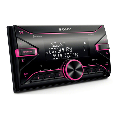
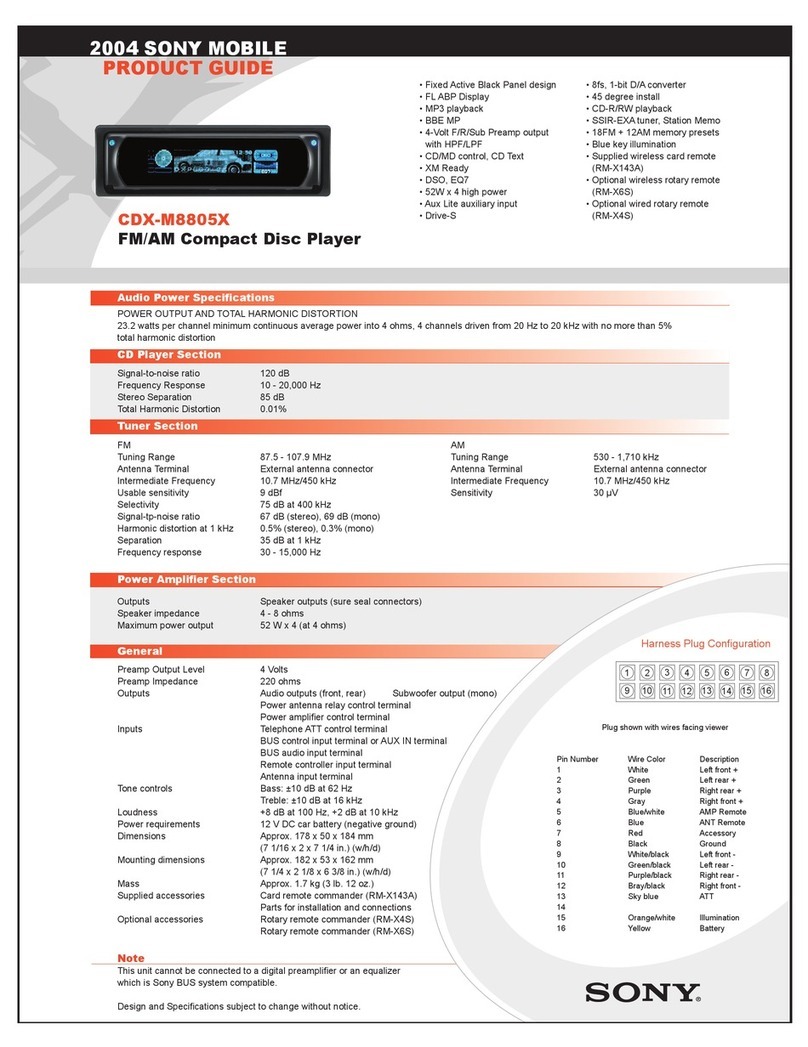
XR-2390/2590
2-Shaft Cassette Receivers
Design and specifications subject to change without notice.
Ω 2390: Tone & Bass Boost Control
Ω 2590: Separate Bass & Treble Controls
Ω 20Wx4 Hi Power Output
Ω 2590: Preamp Output
Ω Positive LCD, Green Illumination
Ω X-tal Lock™SSIR Tuner
Ω 12FM + 6AM Presets, BTM
Ω Auto Reverse Deck
Ω 2590: Dolby B NR, Metal EQ
Ω 2590: Automatic Music Sensor (AMS)
General
Output lead
Tone Controls
Power Requirements
Dimensions
Mass
Supplied Accessories
Optional Accessories
Power antenna relay control lead
XR-2390: High-cut Filter: -10dB at 10kHz Bass Boost: +8dB at 100Hz
XR-2590: Bass +/-8dB at 100 Hz; Treble +/-8dB at 10 kHz
12VDC Car Battery
Approx. 178 x 50 x 140 mm (71/8x 2 x 53/8 in.) (w/h/d)
Approx. 1.2 kg (2 lb. 10 oz.)
Parts for install. & conn. (1 set)
None
Tuner Section
FM
Tuning Range
Antenna Terminal
Intermediate Frequency
Usable Sensitivity
Selectivity
Signal-to-Noise Ratio
Harmonic Distortion @ 1 kHz
Separation
Frequency Response
Capture Ratio
87.5 - 107.9 MHz
External antenna connector
10.7 MHz
13 dBf (75 ohms)
70 dB at 400 kHz
65 dB (stereo); 68 dB (mono)
0.9% (stereo); 0.5% (mono)
33 dB @ 1 kHz
30 - 15,000 Hz
2 dB
AM
Tuning Range
Antenna Terminal
Intermediate Frequency
Sensitivity
530 - 1,710 kHz
External antenna connector
450 kHz
32 µV
Preamplifier Section
Line Outputs XR-2390: None; XR-2590: Rear
Cassette Player Section
Tape Mechanism Type
Tape Track
Frequency Response
Signal/Noise Ratio: Dolby Off
Dolby B On
Wow and Flutter
XR-2390: MG-36SHJ-32
XR-2590: MG-36ASH-32
4-track 2-channel stereo
40 - 15,000 Hz
55dB
63dB (2590 only)
0.13% (WRMS)
Power Amplifier Section
Speaker Outputs
Speaker Impedance
Maximum Power Output
RMS Power Output
Distortion
Front / Rear (sure seal connectors)
4 - 8 ohms
20W x 4 (4 ohms)
7W x4 (20-20kHz, 4 ohms)
Less than 1% THD
Harness Plug Configuration
Plug Shown With Wires Facing Viewer
Pin Number Wire Color Description
1 Gray Right Front Positive
2 Gray/Black Right Front Negative
3 Violet Right Rear Positive
4 Violet/Black Right Rear Negative
5 Green Left Rear Positive
6 Green/Black Left Rear Negative
7 White Left Front Positive
8 White/Black Left Front Negative
9 Blue Antenna Remote
10 Red Accessory +12VDC
11 Black Ground
12 Yellow Constant +12VDC
112
11109
876
5
4
32
