to the interface cable of a car telephone
al cable de interfaz de un teléfono para automóvil
ƒ¤T¤fi„q‚ “”– ⁄f„q˘l
to the +12 V power terminal which is energized at all times
Be sure to connect the black earth lead first.
a un terminal de alimentación de +12 V que esté permanentemente
activado
Asegúrese de conectar primero a este terminal el conductor de puesta a
masa negro.
ƒ‚g–‘‡£‡q„q“”+12 V„q•‰” ⁄l
¨‰—›”¥ ‡s–¶´ƒ–ƒa‰u¡C
to a metal place in the car
First connect the black earth lead, then connect the yellow and red
power input reads.
a un punto metálico del automóvil
En primer lugar, conecte el conductor de puesta a masa negro y, a
continuación, los cables de entrada de alimentación amarillo y rojo.
ƒ¤T¤fi“”“ ˜ ‡¡ƒ
›”¥ ‡s–¶´ƒ–ƒa‰u¡AM«ÆƒA‡s–¶ƒ'M‹ıƒ „q•‰¿Ø⁄J‰u¡C
to the +12 V power terminal which is energized at the accessory position
of the ignition key switch
Notes
•If there is no accessory position, connect to the +12 V power (battery)
terminal which is energized at all times.
Be sure to connect the black earth lead to it first.
•When your car has a built-in FM/AM aerial in the rear/side glass, see
“Notes on the control and power supply leads.”
a un terminal de alimentación de +12 V que se active en la posición para
accesorios de la llave de encendido
Notas
•Si no existe posición para accesorios, realice la conexión al terminal de
alimentación (batería) de +12 V que reciba energía permanentemente.
Asegúrese de conectar primero a este terminal el conductor de puesta a
masa negro.
•Si el automóvil incorpora una antena de recepción de FM/AM en el cristal
trasero/lateral, consulte “Notas sobre los cables de control y de fuente de
alimentación”.
ƒƒb´I⁄ı˘_˝“”»†§Uƒ‚m⁄W‡q„q“”+12 V„q•‰” ⁄l
ø
•
›Y¤Sƒ‡»†§Uƒ‚m¡A«h‰—‡s– ƒ –‘fi ‡q„q“”+12 V„q•‰¡]„qƒ¡^”⁄l¡C
¨‰—›”¥ –N¶´ƒ–ƒa‰u»P¤‡s–¡C
•
–z“”¤T¤fi“”«Æ¡ …‹`… ¡⁄⁄ƒp“G⁄”‚¸ƒ‡FM/AM⁄‰u¡A§Y‰— ‹ ¡§––¤ 'M„q•‰‰u
¶•“ ¡¤¡C
to the power aerial control lead or power supply lead of aerial booster
amplifier
Notes
•It is not necessary to connect this lead if there is no power aerial or aerial
booster, or with a manually-operated telescopic aerial.
•When your car has a built-in FM/AM aerial in the rear/side glass, see
“Notes on the control and power supply leads.”
al cable de control de la antena motorizada, o al cable de fuente de
alimentación del amplificador de antena
Notas
•Si no se dispone de antena motorizada ni de amplificador de antena, o se
utiliza una antena telescópica accionada manualmente, no es necesario
conectar este cable.
•Si el automóvil incorpora una antena de recepción de FM/AM en el cristal
trasero lateral, consulte “Notas sobre los cables de control y de fuente de
alimentación”.
ƒ„q˚⁄ ‰u––¤ ‰u'˛⁄ ‰u⁄£'æ⁄j„“”„q•‰ ‰u
ø
•
ƒpL„q˚⁄ ‰u¡A…W£„¡A'˛¥˛⁄ §@“”fiM” ƒ¡⁄ ‰u¡A«K⁄£¶•‡s–ƒ„ ‰u¡C
•
–z“”¤T¤fi“”«Æ¡ …‹`… ¡⁄⁄ƒp“G⁄”‚¸ƒ‡FM/AM⁄‰u¡A§Y‰— ‹ ¡§––¤ 'M„q•‰‰u
¶•“ ¡¤¡C
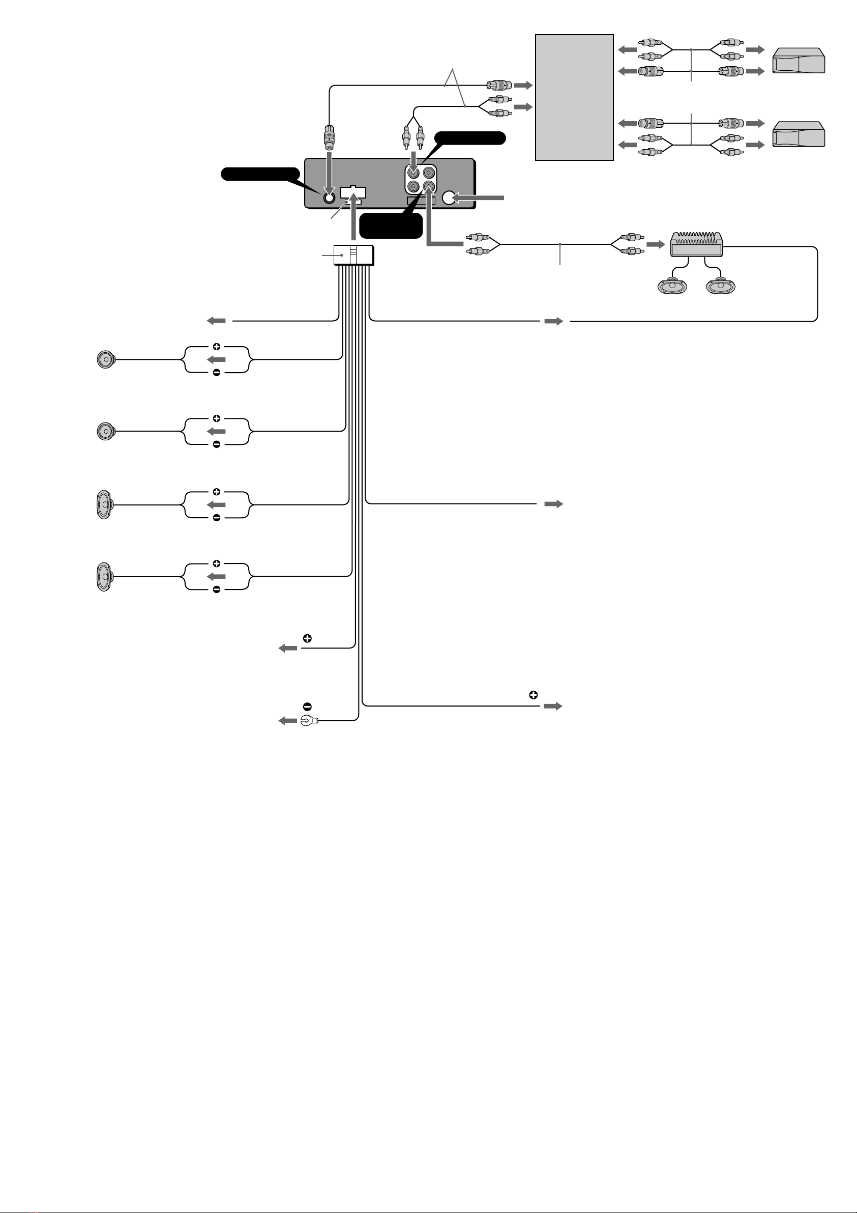
AUDIO OUT
(LINE OUT)
from a car aerial
de la antena del automóvil
¤ƒ¤T¤fi⁄ ‰u
BUS CONTROL IN
Fuse (10 A)
Fusible (10 A)
«OI•(10A)
7
BUS AUDIO IN
AMP REM
Blue/white striped
Con raya azul/blanca
´¯ƒ¡¥ƒ–łfl
Max. supply current 0.3 A
Corriente máx. de alimentación de 0,3 A
‡⁄j·£¤„q‹y0.3 A
Max. supply current 0.1 A
Corriente máx. de alimentación de 0,1 A
‡⁄j·£¤„q‹y0.1 A
ANT REM
Blue
Azul
´¯ƒ
Sky blue
Azul celeste
⁄ ´¯ƒ
ATT
Red
Rojo
‹ıƒ
Yellow
Amarillo
¶ƒ
Black
Negro
¶´ƒ
Purple
Púrpura
ƒ
Green
Verde
”æƒ
Grey
Gris
ƒ˙ƒ
White
Blanco
¥ƒ
Right
Derecho
¥k
Left
Izquierdo
¥“
Right
Derecho
¥k
Left
Izquierdo
¥“
To AMP REMOTE IN of the optional power amplifier.
This connection is only for ampilifiers. Connecting any other system may
damage the unit
a AMP REMOTE IN del amplificador de potencia opcional.
Esta conexión es sólo para amplificadores. La conexión de cualquier otro
sistema puede dañar la unidad.
ƒ¿`˚“”¥\†v'æ⁄j„“”AMP REMOTE IN¡]'æ⁄j„»»––¿Ø⁄J¡^¡C
¥»‡s– ¶¨¥˛''æ⁄j„¡C‡s–¥ƒ¤¥ƒ¤t†˛¥ifl•|•l˜[¥» ¡C
Connection example
Ejemplo de conexiones
‰u‚‡s– „ˇ¤
Source selector
Selector de fuente
› •‰¿ „
Supplied with the CD/MD changer
Suministrado con el cambiador de CD/MD
“–a' CD/MD ·«”—
Supplied with the XA-C30
Suministrado con el XA-C30
“–a' XA-C30
RCA pin cord (not supplied)
Cable con clavijas RCA (no suministrado)
RCA ”‚}„q‰u¡]L“–a¡^
Notes on the control and power supply leads
•The power aerial control lead (blue) supplies +12 V DC when you turn on
the unit.
•When your car has a built-in FM/AM aerial in the rear/side glass, it is
necessary to connect the power aerial control lead (blue) or the accessory
power input lead (red) to the power terminal of the existing aerial
booster. For details, consult your dealer.
•A power aerial without a relay box cannot be used with this unit.
Memory hold connection
When the yellow power input lead is connected, power will always be
supplied to the memory circuit even when the ignition switch is turned off.
Notes on speaker connection
•Before connecting the speakers, turn the unit off.
•Use speakers with an impedance of 4 to 8 ohms, and with adequate
power handling capacities. Otherwise, the speakers may be damaged.
•Do not connect the terminals of the speaker system to the car chassis,
and do not connect the terminals of the right speaker with those of the
left speaker.
•Do not attempt to connect the speakers in parallel.
•Do not connect any active speakers (with built-in amplifiers) to the
speaker terminals of the unit. Doing so may damage the active speakers.
Be sure to connect passive speakers to these terminals.
Notas sobre los cables de control y de fuente de alimentación
•El conductor de control de la antena motorizada (azul) suministrará
+ 12 V CC cuando conecte la alimentación de la unidad.
•Si se ha instalado una antena de recepción de FM/AM en el cristal trasero
lateral del automóvil, es necesario conectar el cable de control de la
antena motorizada (azul) o el cable auxiliar de entrada de alimentación
(rojo) al terminal de alimentación del amplificador de antena existente.
Para obtener información detallada, consulte a su proveedor.
•Con esta unidad no podráemplearse una antena motorizada desprovista
de caja de relé.
Conexión para protección de la memoria
Si conecta el cable de entrada de alimentación amarillo, el circuito de la
memoria siempre recibiráalimentación, aunque ponga la llave de
encendido en la posición de apagado.
Notas sobre la conexión de los altavoces
•Antes de conectar los altavoces, desconecte la alimentación de la unidad.
•Utilice altavoces con una impedancia de 4 a 8 Ohmios, y con la potencia
máxima admisible adecuada, ya que de lo contrario podría dañarlos.
•No conecte los terminales del sistema de altavoces al chasis del
automóvil, ni los del altavoz izquierdo a los del derecho.
•No intente conectar los altavoces en paralelo.
•No conecte altavoces activos (con amplificadores incorporados) a los
terminales de altavoces de la unidad. Si lo hiciese, podría dañar tales
altavoces. Por lo tanto, cerciórese de conectar altavoces pasivos a estos
terminales.
––¤ 'M„q•‰‰u¶•“
•
•–z¥·¶}„fi ¡A„q˚⁄ ‰u“”––¤ ‰u¡}´¯ƒ ¡~§Y¥io¥˝12V“‰‹y„q¡C
•
–z“”¤T¤fi“”«Æ¡ …‹`… ¡⁄⁄ƒp“G⁄”‚¸ƒ‡FM/AM⁄‰u¡A§Y‰—§ „q˚⁄ ‰u––¤ ‰u
¡]´¯ƒ ¡^'˛»†§U“”„q•‰¿Ø⁄J‰u¡]‹ıƒ ¡^‡s–¤†{ƒ‡“”⁄ ‰u…W£„“”„q•‰” ⁄l⁄W¡C
‚ † ⁄”fie¡A‰—‹¢‚¥''–¡C
•
¥» ⁄£fl ¤ˇ¥˛⁄£¤ª‡˘˜~„q‰c“”„q˚⁄ ‰u¡C
«O«ø O—¥\fl “”‡s–“k
•‡s–ƒn¶ƒ„q•‰¿Ø⁄J‰ufi¡A§Y¤ˇ¤T¤fi o˚´I⁄ı˘_˝‡Q´ƒb„q•‰⁄`´_⁄§‡B¡
„q•‰⁄·˜~˜–N„q‹y¤„O—¥\fl ¥˛„q‚¡A¥H«O«ø'O— “”…˘ ¡C
‡s–·›`n „¶•“
•
‡s–·›`n „„q‰u⁄§«e¡A‰—¥ ˆ –…¥» „q•‰¡C
•
‰—¤ˇ¥˛4ƒ8£[“ § ¤ˆ¥B¤ªƒ‡¤‹ ¥\†v“”·›`n „¡C§_«h•|•lˆa·›`n „¡C
•
⁄£¥i–N·›`n „“”” ⁄l‡s–ƒ¤T¤fi'‡‰L¡A⁄]⁄£¥i–N¥“·›`n „'M¥k·›`n „‹ ‡s–
•
⁄£¥i¤ˆ`p·›`n „¡C
•
⁄£¥i‡s– ƒ‡•‰·›`n „¡]⁄”‚¸ƒ‡'æ⁄j„“ ¡^ƒ ¥» “”·›`n „” ⁄l¡C§_«h•|•lˆaƒ
·›`n „¡Cƒ]ƒ„¡A‡o¤˙” ⁄l¥ufl‡s–L•‰·›`n „¡C
XR-C2600