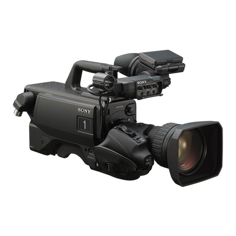
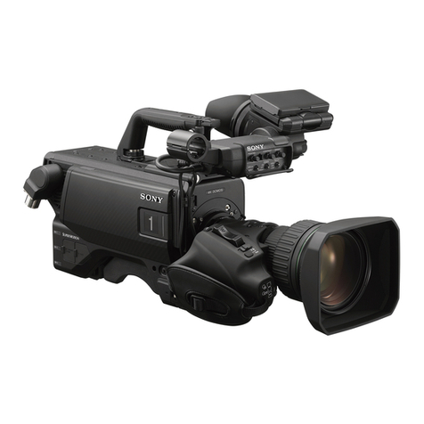
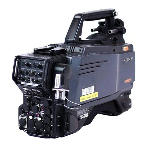
Sony super motion hdc4300 User manual

COLOR CAMERA
HDC4300
SERVICE MANUAL
1st Edition

警告
このマニュアルは, サービス専用です。
お客様が, このマニュアルに記載された設置や保守, 点検, 修理などを行うと感電や火災,
人身事故につながることがあります。
危険をさけるため, サービストレーニングを受けた技術者のみご使用ください。
WARNING
This manual is intended for qualified service personnel only.
To reduce the risk of electric shock, fire or injury, do not perform any servicing other than that
contained in the operating instructions unless you are qualified to do so. Refer all servicing to
qualified service personnel.
WARNUNG
Die Anleitung ist nur für qualifiziertes Fachpersonal bestimmt.
Alle Wartungsarbeiten dürfen nur von qualifiziertem Fachpersonal ausgeführt werden. Um die
Gefahr eines elektrischen Schlages, Feuergefahr und Verletzungen zu vermeiden, sind bei
Wartungsarbeiten strikt die Angaben in der Anleitung zu befolgen. Andere als die angegeben
Wartungsarbeiten dürfen nur von Personen ausgeführt werden, die eine spezielle Befähigung
dazu besitzen.
AVERTISSEMENT
Ce manual est destiné uniquement aux personnes compétentes en charge de l’entretien. Afin
de réduire les risques de décharge électrique, d’incendie ou de blessure n’effectuer que les
réparations indiquées dans le mode d’emploi à moins d’être qualifié pour en effectuer d’autres.
Pour toute réparation faire appel à une personne compétente uniquement.
Model Name Serial No.
HDC4300 (SY) 10001 and Higher
HDC4300 (CED) 40001 and Higher
HDC4300 (J) 30001 and Higher
HDC4300 (CN) 50001 and Higher
HDC4300

For safety, do not connect the connector for peripheral
device wiring that might have excessive voltage to the
following port(s).
: NETWORK TRUNK
Follow the instructions for the above port(s).
安全のために,周辺機器を接続する際は,過大電圧を
持つ可能性があるコネクターを以下のポートに接続し
ないでください。
:NETWORKTRUNK
上記のポートについては本書の指示に従ってください。
CAUTION
Use of controls or adjustments or performance of
procedures other than those specified herein may
result in hazardous radiation exposure.
CAUTION
The use of optical instruments with this product will
increase eye hazard.
This HD COLOR CAMERA is classified as a CLASS 1 LASER PRODUCT.
CLASS 1 LASER PRODUCT
LASER KLASSE 1 PRODUKT
LUOKAN 1 LASERLAITE
KLASS 1 LASER APPARAT
HDC4300

CAUTION
Danger of explosion if battery is incorrectly replaced.
Replace only with the same or equivalent type rec-
ommended by the manufacturer.
When you dispose of the battery, you must obey the
law in the relative area or country.
ATTENTION
Il y a danger d’explosion s’il y a remplacement incor-
rect de la batterie. Remplacer uniquement avec
une batterie du même type ou d’un type équivalent
recommandé par le constructeur.
Lorsque vous mettez la batterie au rebut, vous devez
respecter la législation en vigueur dans le pays ou la
région où vous vous trouvez.
VORSICHT
Explosionsgefahr bei Verwendung falscher Batterien.
Batterien nur durch den vom Hersteller empfohlenen
oder einen gleichwertigen Typ ersetzen.
Wenn Sie die Batterie entsorgen, müssen Sie die
Gesetze der jeweiligen Region und des jeweiligen
Landes befolgen.
注意
指定以外の電池に交換すると,破裂する危険があり
ます。
必ず指定の電池に交換してください。
使用済みの電池は,国または地域の法令に従って
処理してください。
FÖRSIKTIGHET!
Fara för explosion vid felaktigt placerat batteri.
Byt endast mot samma eller likvärdig typ av batteri,
enligt tillverkarens rekommendationer.
När du kasserar batteriet ska du följa rådande lagar
för regionen eller landet.
PAS PÅ
Fare for eksplosion, hvis batteriet ikke udskiftes
korrekt.
Udskift kun med et batteri af samme eller tilsvarende
type, som er anbefalet af fabrikanten.
Når du bortskaffer batteriet, skal du følge
lovgivningen i det pågældende område eller land.
HUOMIO
Räjähdysvaara, jos akku vaihdetaan virheellisesti.
Vaihda vain samanlaiseen tai vastaavantyyppiseen,
valmistajan suosittelemaan akkuun.
Noudata akun hävittämisessä oman maasi tai
alueesi lakeja.
FORSIKTIG
Eksplosjonsfare hvis feil type batteri settes i.
Bytt ut kun med samme type eller tilsvarende
anbefalt av produsenten.
Kasser batteriet i henhold til gjeldende avfallsregler.
⌞ᝅ
⌞ᝅ
ྸᴪᦘⲺ⭫⊖у↙⺤θቧՐᴿ⠼⛮Ⲻধ䲟Ⱦ
ᴪᦘж㊱ශᡌ䙖᧞㦆Ⲻ⭫⊖ශȾ
༺⨼⭫⊖ᰬθᗻ亱䚫ᆾީ൦ᡌളᇬⲺ⌋ᗁȾ
HDC4300

Table of Contents
Manual Structure
Manual Structure..........................................................................................................................7
Related manuals...........................................................................................................................7
Non-disclosed boards.....................................................................................................................7
1. Service Overview
1-1. Checking before Installation.................................................................................................. 1-1
1-1-1. Checking the ROM and Software Version..............................................................................1-1
1-2. Connectors and Cables........................................................................................................1-2
1-2-1. Connector Input/Output Signals........................................................................................1-2
1-2-2. Wiring Diagrams for Cables............................................................................................1-6
1-2-3. Connection Connectors/Cables.........................................................................................1-6
1-2-4. Note in Connecting BPU Connector................................................................................... 1-7
1-3. Location of Printed Circuit Boards............................................................................................1-8
1-4. Notes on Board Replacing...................................................................................................1-10
1-4-1. Description on EEPROM Data........................................................................................1-10
1-4-2. Adjustment and Setting Required when Replacing the SY-408 Board............................................... 1-10
1-5. Fixtures/Measuring Equipments List........................................................................................ 1-11
1-5-1. Service Tools.......................................................................................................... 1-11
1-5-2. Measuring Equipment.................................................................................................1-11
1-6. Microphone Power and Intercom Settings...................................................................................1-12
1-6-1. Outputting Microphone Power Voltage +12 V (AB-Power)..........................................................1-12
1-6-2. Intercom Settings......................................................................................................1-12
1-7. Flexible Card Wire and Coaxial Cable.......................................................................................1-14
1-7-1. Connecting/Disconnecting Flexible Card Wire.......................................................................1-14
1-7-2. Forming Flexible Card Wire.......................................................................................... 1-15
1-7-3. Disconnecting/Connecting Fine-Wire Coaxial Cable.................................................................1-16
1-7-4. Connecting/Disconnecting Coaxial Cable............................................................................ 1-17
1-8. Explanation of Prism Number............................................................................................... 1-19
1-9. Circuit Protection Parts...................................................................................................... 1-20
1-9-1. Fuses...................................................................................................................1-20
1-9-2. Circuit Protection Element............................................................................................1-20
1-10. Lead-free Solder............................................................................................................. 1-22
2. Periodic Maintenance and Inspection
2-1. Recommended Replacement Parts............................................................................................2-1
2-2. Cleaning the Air Vents........................................................................................................ 2-2
2-3. Replacing Lithium Battery....................................................................................................2-3
2-3-1. Note on Replacement of Lithium Battery ..............................................................................2-3
2-3-2. Replacing Procedure....................................................................................................2-3
2-4. Cleaning of Connector/Cable................................................................................................. 2-4
2-4-1. When the Optical Connector Cleaner (Commercially Available) is Available.........................................2-4
2-4-2. When the Optical Connector Cleaner (Commercially Available) is not Available (Connectors/Cables of LEMO) ...2-5
2-4-3. When the Optical Connector Cleaner (Commercially Available) is not Available (Tajimi Electronics Co., Ltd.).... 2-6
2-4-4. When the Optical Connector Cleaner (Commercially Available) is not Available (Connector).......................2-8
HDC4300 1

3. Troubleshooting
4. Replacement of Main Parts
4-1. General Information for Parts Replacement.................................................................................. 4-1
4-1-1. Index....................................................................................................................4-1
4-1-2. Basic Knowledge.......................................................................................................4-3
4-1-3. Tightening Torque...................................................................................................... 4-3
4-2. Inside Panel Assembly........................................................................................................ 4-4
4-3. Outside Block................................................................................................................. 4-5
4-3-1. Outside Panel Assembly................................................................................................4-5
4-3-2. MEM-147 Board/TX-146 Board....................................................................................... 4-7
4-3-3. DC Fan (Outside panel)...............................................................................................4-10
4-3-4. CN-3434 Board........................................................................................................4-11
4-3-5. Optical Multi Cable Assembly........................................................................................4-12
4-3-6. PROMPTER Connector...............................................................................................4-13
4-3-7. Coaxial Cable......................................................................................................... 4-14
4-4. FD (Filter Disk) Assembly...................................................................................................4-16
4-5. Front Assembly.............................................................................................................. 4-17
4-6. OHB Block...................................................................................................................4-19
4-6-1. OHB Assembly........................................................................................................4-19
4-6-2. IF-1278 Board.........................................................................................................4-20
4-7. Handle Block.................................................................................................................4-21
4-7-1. LE-376 Board/SW-1524 Board....................................................................................... 4-21
4-7-2. VF Connector (CN-3422 Board)......................................................................................4-22
4-7-3. SW-1525 Board....................................................................................................... 4-25
4-8. Main Chassis Block..........................................................................................................4-26
4-8-1. SY-408 Board/AT-189 Board..........................................................................................4-26
4-8-2. Power Block Assembly (RE-291 Board/PS-836 Board)..............................................................4-27
4-8-3. DPR-370 Board....................................................................................................... 4-30
4-8-4. MB-1214 Board.......................................................................................................4-32
4-8-5. SW-1527 Board....................................................................................................... 4-34
4-8-6. CN-3423 Board........................................................................................................4-35
4-8-7. SW-1672 Board....................................................................................................... 4-36
4-8-8. CN-3421 Board........................................................................................................4-37
4-8-9. SW-1528 Board....................................................................................................... 4-37
4-8-10. CN-3424 Board........................................................................................................4-38
4-8-11. CN-3426 Board........................................................................................................4-40
4-8-12. SW-1531 Board....................................................................................................... 4-41
4-8-13. BUILD UP Connector.................................................................................................4-41
4-9. DC Fan (Front)...............................................................................................................4-44
4-10. DC Fan (Rear)............................................................................................................... 4-46
4-11. MIC Panel Block.............................................................................................................4-47
4-11-1. CN-3429 Board/CN-3427 Board......................................................................................4-47
4-11-2. AUDIO IN Connector (CN-3425 Board)............................................................................. 4-49
4-11-3. PROMPTER/GENLOCK/TEST OUT Connector (CN-3428 Board).................................................4-50
4-11-4. REMOTE Connector (CN-3430 Board).............................................................................. 4-50
4-11-5. DC IN Connector (CN-3432 Board).................................................................................. 4-51
4-12. INCOM Panel Assembly.....................................................................................................4-52
4-12-1. INTERCOM Connector (CN-3431 Board)........................................................................... 4-52
4-12-2. SW-1530 Board/SW-1530A Board................................................................................... 4-53
HDC4300 2
5. Electrical Alignment
5-1. Preparations................................................................................................................... 5-1
5-1-1. Required Equipment, Tool..............................................................................................5-1
5-1-2. File Data at Adjustment................................................................................................ 5-1
5-1-3. Handling the Grayscale Chart.......................................................................................... 5-2
5-1-4. Setup Menu.............................................................................................................5-4
5-1-5. Connection of Equipment.............................................................................................. 5-5
5-1-6. Initial Settings.......................................................................................................... 5-5
5-1-7. Setup Menu Correspondence List...................................................................................... 5-6
5-2. Automatic Adjustment........................................................................................................ 5-9
5-2-1. Execute the Automatic Level Setup....................................................................................5-9
5-3. Camera System Adjustment................................................................................................. 5-10
5-3-1. Black Set Adjustment................................................................................................. 5-10
5-3-2. Sensitivity Adjustment................................................................................................ 5-10
5-3-3. Black Shading Adjustment............................................................................................5-12
5-3-4. White Shading Adjustment............................................................................................5-13
5-4. Video System Level Adjustment.............................................................................................5-17
5-4-1. H/V Ratio Adjustment.................................................................................................5-17
5-4-2. Detail Level Adjustment.............................................................................................. 5-18
5-4-3. Crispening Adjustment................................................................................................5-19
5-4-4. Level Dependent Adjustment......................................................................................... 5-19
5-4-5. Detail Clip Adjustment................................................................................................5-20
5-4-6. Auto-iris Adjustment..................................................................................................5-22
5-4-7. Pedestal Level Adjustment............................................................................................5-22
5-4-8. Flare Adjustment......................................................................................................5-23
5-4-9. Gamma Correction Adjustment.......................................................................................5-24
5-4-10. Knee Point/Knee Slope Adjustment...................................................................................5-25
5-4-11. White Clip Level Adjustment.........................................................................................5-26
5-4-12. File Store.............................................................................................................. 5-26
5-5. ND Offset Adjustment.......................................................................................................5-28
5-5-1. White Balance Compensation.........................................................................................5-28
5-6. RPN Compensation..........................................................................................................5-30
5-6-1. Automatic Compensation (APR)......................................................................................5-30
5-6-2. Manual RPN Compensation Adjustment............................................................................. 5-31
5-6-3. Procedures to be Taken when the RPN Compensation Fails..........................................................5-32
5-6-4. Performing Automatic RPN Detection Effectively ...................................................................5-33
6. Software Upgrade
6-1. Upgrading Software Programs ............................................................................................... 6-1
6-1-1. Upgrading Camera Application ........................................................................................6-1
6-1-2. Upgrading OS...........................................................................................................6-1
6-2. PLD............................................................................................................................6-3
6-2-1. Corresponding PLD.................................................................................................... 6-3
6-2-2. Upgrading PLD Data................................................................................................... 6-3
6-3. Forced Version Update........................................................................................................ 6-5
6-3-1. Forced Version Update of Software or PLD Data......................................................................6-5
HDC4300 3

7. File System
7-1. File Structure..................................................................................................................7-1
7-1-1. Structure of Paint Related Files.........................................................................................7-2
7-2. Operator File.................................................................................................................. 7-3
7-2-1. Operator File Operation................................................................................................ 7-3
7-3. Preset Operator File........................................................................................................... 7-4
7-3-1. Preset Operator File Operation......................................................................................... 7-4
7-4. Scene File..................................................................................................................... 7-5
7-4-1. Scene File Operation................................................................................................... 7-5
7-5. Reference File.................................................................................................................7-7
7-5-1. Reference File Operation...............................................................................................7-7
7-6. Lens File.......................................................................................................................7-9
7-6-1. Lens File................................................................................................................7-9
7-7. OHB File.....................................................................................................................7-11
7-7-1. OHB File Operation...................................................................................................7-11
7-8. File Items.....................................................................................................................7-13
8. Setup Menu
8-1. Overview of Setup Menu......................................................................................................8-1
8-1-1. How to Display the SERVICE Menu/ How to Change the Setting Values.............................................8-1
8-1-2. Settable Special Functions..............................................................................................8-1
8-2. SERVICE Menu...............................................................................................................8-3
8-2-1. SERVICE Menu List................................................................................................... 8-3
8-2-2. Description of SERVICE Menu........................................................................................ 8-3
9. Circuit Description
9-1. Optical System (OHB Block)................................................................................................. 9-1
9-1-1. BI-291 board............................................................................................................9-1
9-1-2. IF-1278 board...........................................................................................................9-1
9-2. Signal Processing/Transmission System......................................................................................9-2
9-2-1. TX-146 Board.......................................................................................................... 9-2
9-2-2. MEM-147 Board........................................................................................................9-2
9-2-3. DPR-370 Board.........................................................................................................9-2
9-3. System Control System....................................................................................................... 9-3
9-3-1. SY-408 Board...........................................................................................................9-3
9-3-2. AT-189 Board...........................................................................................................9-3
9-3-3. MB-1214 Board........................................................................................................ 9-3
10. Spare Parts
10-1. Note on Repair Parts.........................................................................................................10-1
10-2. Exploded Views..............................................................................................................10-2
Inside-1 .............................................................................................................................10-2
Inside-2 .............................................................................................................................10-3
Outside-1 ...........................................................................................................................10-4
Outside-2 ...........................................................................................................................10-5
Outside-3 ...........................................................................................................................10-6
HDC4300 4

Front Panel .........................................................................................................................10-7
OHB Block .........................................................................................................................10-8
Incom Panel ........................................................................................................................10-9
Mic Panel .........................................................................................................................10-10
PS Block ..........................................................................................................................10-12
DPR Block ........................................................................................................................10-14
MB Block .........................................................................................................................10-15
Front SW Block ...................................................................................................................10-16
Front Fan ..........................................................................................................................10-17
Hotshoe Block ....................................................................................................................10-18
Handle-1 ..........................................................................................................................10-19
Handle-2 ..........................................................................................................................10-20
Handle-3 ..........................................................................................................................10-21
10-3. Supplied Accessories.......................................................................................................10-22
Supplied Accessories .............................................................................................................10-22
11. Block Diagrams
Overall.................................................................................................................................11-1
Frame Wiring..........................................................................................................................11-4
HDC4300 5


Manual Structure
Manual Structure
This manual is intended for the use of the system engineers and the service engineers, and provides the limited
information for block service and the information related to maintenance of the unit,such as service overview, periodic
maintenance and inspection, troubleshooting, replacement of main parts, electrical alignment, software upgrade, file
system, setup menu and circuit description.
Related manuals
The following manuals are available for this model.
If any of these manuals is required, please contact your local Sony Sales Office/Service Center.
• Operation Manual CD-ROM (Supplied with this unit)
This manual contains information required to operate and use the unit.
• Factory Service Manual (Available on request)
This manual provides the limited information for component service and the information related to maintenance
of the unit.
Non-disclosed boards
Replacement in units of mount boards or mount components is not possible for boards shown below. Therefore, their
circuit diagrams, mount drawings, and components lists are not disclosed.
• BI-291 board
• SE-1093 board
HDC4300 7


Section 1
Service Overview
1-1. Checking before Installation
1-1-1. Checking the ROM and Software Version
When connecting the peripheral equipment in the list below to this unit, be sure to check that the ROM and software
version on each peripheral device is corresponding to the camera to be connected.
If the ROM and software version is lower than the specified below, be sure to perform ROM replacement and updating
the software.
If ROM replacement and updating the software are required, contact your local Sony Sales Office/Service Center.
ROM
Peripheral Equip-
ment
Board Name Ref. No. ROM Version
CNU-700 AT-89 board or AT-89A board IC4, IC5 Ver. 1.30 and higher
Software
Peripheral Equipment Board Name Software Version
RCP-920/921 MPU-143 board Ver. 1.11 and higher
RCP-1000/1001 MPU-152 board Ver. 2.50 and higher
RCP-1500/1501/1530 MPU-153 board Ver. 2.50 and higher
HDCU2000/2500 AT-167A board Ver. 2.21 and higher
MSU-900/950 CPU-396 board Ver. 1.21 and higher
MSU-1000 MPU-150 board Ver. 2.50 and higher
MSU-1500 MPU-151 board Ver. 2.50 and higher
BPU4000 AT-189 board Ver. 3.00 and higher
HDC4300 1-1

1-2. Connectors and Cables
1-2-1. Connector Input/Output Signals
19
22
1
21
15
16
1214 5 6
2
7
13
10
18
20
9
17
3
11
4
8
Input/Output Signals
1. BPU
10.692 Gbps/10.681319 Gbps serial
2. PROMPTER/GENLOCK
BNC type 75 Ω, 1.0 V p-p
3. SDI 1
BNC type
3G SDI signal
SMPTE 424M/425M-B compliant
0.8 Vp-p 75 Ω, 2.97 Gbps/2.9679 Gbps Serial
or HD SDI signal
SMPTE 292M/372M, BTA-S004 compliant
0.8 Vp-p 75 Ω, 1.485 Gbps/1.4835 Gbps Serial
4. SDI 2
BNC type
Output: HD SDI signal
SMPTE 292M/372M, BTA-S004 compliant
0.8 Vp-p 75 Ω, 2.97 Gbps/2.9679 Gbps Serial
Input: HD SDI signal
SMPTE 292M, BTA-S004 compliant
0.8 Vp-p 75 Ω, 1.485 Gbps/1.4835 Gbps Serial
5. SDI-MONI
BNC type
HD SDI signal
SMPTE 292M/372M, BTA-S004 compliant
(HDC2500/2570)
SMPTE 292M, BTA-S004 compliant
(HDC2400/2550)
0.8 Vp-p 75 Ω, 1.485 Gbps/1.4835 Gbps Serial
or SD SDI signal
SMPTE 259M compliant
0.8 Vp-p 75 Ω, 270 Mbps Serial
6. TEST OUT
BNC type 75 Ω, 1.0 V p-p
7. EARPHONE
Stereo mini jack
HDC4300 1-2

8. PROMPTER2
BNC type 75 Ω, 1.0 V p-p
9. RET CTRL
6-pin, Female
- External View -
34
16
25
No
.
Signal I/O Specifications
1 INCOM 1
MIC-ON/OFF
IN Zi ≧ 10 KΩ
ON: GND
OFF: OPEN
2 INCOM 2
MIC-ON/OFF
IN Zi ≧ 10 KΩ
ON: GND
OFF: OPEN
3 GND — —
4 RET 3-
ON/OFF
IN Zi ≧ 10 KΩ
ON: GND
OFF: OPEN
5 RET 1-
ON/OFF
IN Zi ≧ 10 KΩ
ON: GND
OFF: OPEN
6 RET 2-
ON/OFF
IN Zi ≧ 10 KΩ
ON: GND
OFF: OPEN
10. DC OUT
1
23
4
- External View -
4-pin, Female
No. Signal I/O Specifications
1 UNREG GND — GND for power
2 NC — No connection
3 NC — No connection
4 UNREG OUT +12 V dc, 500 mA (max)
11. REMOTE
17
6
5
4
3
2
8
- External View -
8-pin, Female
No. Signal I/O Specifications
1 • TX (X): for
RCP
• TX1 (+): for
TRUNK
(RS-422A)
OUT • SERIAL DA-
TA OUT: for
RCP
• TRUNK1 DA-
TA OUT: for
RS-422A
2 • TX (Y): for
RCP
• TX1 (–): for
TRUNK
(RS-422A)
OUT
3 • RX (X): for
RCP
• RX1 (+): for
TRUNK
(RS-422A)
IN • SERIAL DA-
TA IN: for
RCP
• TRUNK1 DA-
TA IN: for
RS-422A
4 • RX (Y): for
RCP
• RX1 (–): for
TRUNK
(RS-422A)
IN
5 TX-GND — GND for TX
6 UNREG-OUT OUT UNREG +10.5 V to
+17 V dc, 200 mA
(max)
7 UNREG-GND — GND for UNREG-
OUT
8 RCP-PIX: for RCP OUT 75 Ω, 1.0 V p-p (SD
Video)
CHASSIS GND:
for TRUNK
(RS-422A)
— CHASSIS GND
12. AUDIO IN CH1/CH2
1
2
3
- External View -
(0 dBu = 0.775 V rms)
XLR 3-pin, Female
No. Signal I/O Specifications
1 AUDIO 1/2 (G) — –60 dBu, –50 dBu,
–40 dBu, –30 dBu,
–20 dBu selectable, High
impedance, Balanced
2 AUDIO 1/2 (X) IN
3 AUDIO 1/2 (Y) IN
HDC4300 1-3

13. INTERCOM 1, 2
- External View -
1
2
5
43
XLR 5-pin, Female
(0 dBu = 0.775 V rms)
No. Signal I/O Specifications
1 EXT-INCOM-T
(Y)
IN • –20 dBu: Carbon
microphone
• –60 dBu: Dynam-
ic microphone
2 EXT-INCOM-T
(X)
IN
3 GND — GND
4 EXT-INCOM-
LEFT (X)
OUT 0 dBu
5 EXT-INCOM-
RIGHT (X)
OUT
14. DC IN
1
23
4
- External View -
XLR 4-pin, Male
No. Signal I/O Specifications
1 EXT_DC (C) — GND for DC (+)
2 NC — No connection
3 NC — No connection
4 EXT_DC (H) IN +10.5 V to 17 V dc
15. LENS
- External View -
12-pin, Female
12 11
46
73
28
91
10
5
No. Signal I/O Specifications
1 RET VIDEO
ENABLE
IN • ENABLE: 0 V
• DISABLE: +5 V or
OPEN
Continued
No. Signal I/O Specifications
2 VTR CTL IN • ENABLE: 0 V
• DISABLE: +5 V or
OPEN
3 GND — GND for UNREG
4 SERVO
MA/AT
OUT • AUTO: +5 V
• MANU: 0 V or
OPEN
5 IRIS POSI-
TION
OUT +3.4 V (F16) to +6.2 V
(F2.8)
6 UNREG OUT +10.5 V to +17 V
7 IRIS POSI-
TION
IN +3.4 V (F16) to +6.2 V
(F2.8)
8 IRIS AT/MA OUT • AUTO IRIS: 0 V
• MANUAL IRIS:
+5 V
9 EXTENDER
ON/OFF
IN • EX 2 ON: GND
• EX 0.8 ON: 30 kΩ
to GND
• OFF: OPEN
30 kΩ
EX 2 ON
EX 0.8 ON
10 ZOOM POSI-
TION
IN • WIDE: 2 V
• TELE: 7 V
11 FOCUS POSI
(LENS RX)
IN • ∞: 7 V
• min.: 2 V
12 FOCUS POSI
(LENS TX)
OUT —
16. VF
- External View -
20-pin, Female
No. Signal I/O Specifications
1 S-DATA IN/
OUT
TTL level
2 NC — No connection
3 NC — No connection
4 SCK OUT TTL level
5 NC — No connection
6 NC — No connection
7 NC — No connection
8 G TALLY OUT ON : 5 V
OFF : GND
9 NC — No connection
10 NC — No connection
Continued
HDC4300 1-4

No. Signal I/O Specifications
11 NC — No connection
12 Y VIDEO OUT 1.0 V p-p,
Zo = 75 Ω
13 VIDEO GND — GND for VIDEO
14 Pb VIDEO OUT ±0.35 V p-p,
Zo = 75 Ω
15 Pr VIDEO OUT ±0.35 V p-p,
Zo = 75 Ω
16 NC — No connection
17 R TALLY OUT ON : 5 V
OFF : GND
18 NC — No connection
19 UNREG GND — GND for UNREG
20 UNREG OUT +10.5 V to +17 V
17. CRANE
- External View -
2
9
1
8
10
1211
37
64 5
12-pin, Female
No. Signal I/O Specifications
1 Pr VIDEO (X) OUT ±0.35 V p-p,
Zo = 75Ω
2 Pb VIDEO (X) OUT ±0.35 V p-p,
Zo = 75Ω
3 NC — No connection
4 • TX0 (+):
for
RS-422A
• TX1: for
RS-232C
OUT TRUNK data out
5 • TX0 (–):
for
RS-422A
• TX0: for
RS-232C
OUT
6 • RX0 (–):
for
RS-422A
• RX0: for
RS-232C
IN TRUNK data in
7 • RX0 (+):
for
RS-422A
• RX1: for
RS-232C
IN
8 GND (VIDEO) — GND for VIDEO
9 Y VIDEO (X) OUT 1.0 V p-p,
Zo = 75Ω
10 GND — GND for SCL/SDA
Continued
No. Signal I/O Specifications
11 SCL EXT-VF OUT TTL level
12 SDA EXT-VF IN/
OUT
TTL level
18. TRACKER
81
54
10 9 27
63
- External View -
10-pin, Female
No. Signal I/O Specifications
1 TRACKER
LEFT
OUT TRACKER RE-
CEIVE/
PGM –20 dBu unbal-
anced
2 GND (TALK) — GND for TRACKER
TALK
3 GND (RE-
CEIVE/PGM/TL
)
— GND for
RECEIVE/PGM/TL
4 TRACKER
RIGHT
OUT TRACKER RE-
CEIVE/
PGM –20 dBu unbal-
anced
5 UNREG OUT +12 V (+10.5 to
+17.0 V)
6 GND (UNREG) — GND for UNREG
7 TRACKER
TALK (X)
IN TRACKER TALK 0
dBu /
–20 dBu, High impe-
dance balanced
8 TRACKER
TALK (Y)
IN
9 G TALLY OUT ON: GND
OFF: High impe-
dance (Open collec-
tor)
10 R TALLY OUT ON: GND
OFF: High impe-
dance (Open collec-
tor)
19. MIC 1 IN
1
2
3
- External View -
(0 dBu = 0.775 V rms)
XLR 3-pin, Female
HDC4300 1-5

No. Signal I/O Specifications
1 MIC 1 (G) — –60 dBu, –50 dBu,
–40 dBu, –30 dBu,
–20 dBu selectable, High
impedance, Balanced
2 MIC 1 (X) IN
3 MIC 1 (Y) IN
20. USB
USB (Series A), 4-pin
Signal standard: USB standard Ver. 2.0
- External View -
14
No. Signal I/O Specifications
1 VBUS OUT USB Vcc (+5 V)
2 D+ IN/
OUT
USB+
3 D– IN/
OUT
USB–
4 GND — GND
21. LAN
18
- External View -
8-pin, RJ-45, 10Base-T/100Base-TX
No. Signal I/O Specifications
1 TRD + (0) IN/
OUT
Transmitted/Received
Data + (0)
2 TRD - (0) IN/
OUT
Transmitted/Received
Data - (0)
3 TRD + (1) IN/
OUT
Transmitted/Received
Data + (1)
4 TRD + (2) IN/
OUT
Transmitted/Received
Data + (2)
5 TRD - (2) IN/
OUT
Transmitted/Received
Data - (2)
6 TRD - (1) IN/
OUT
Transmitted/Received
Data - (1)
7 TRD + (3) IN/
OUT
Transmitted/Received
Data + (3)
8 TRD - (3) IN/
OUT
Transmitted/Received
Data - (3)
22. DC OUT
- External View -
2-pin, Female
12
No
.
Signal I/O Specifications
1 LIGHT +12 V OUT +12 V dc, 2.5 A (max)
2 GND — GND for power
1-2-2. Wiring Diagrams for Cables
CCA-5 Cable (for REMOTE connector)
BrownBrown
Brown
Red
Red
White
White
White
Orange
Black
— 8P CONNECTOR (MALE) —
(WIRING SIDE)
INTERCOM MIC Cable
1. Balance (HEAD SET menu UNBAL: OFF)
G
XINTERCOM
MIC
Y
2. Unbalance (HEAD SET menu UNBAL: ON)
XINTERCOM
MIC
Y
1-2-3. Connection Connectors/Cables
Connection made with the connector panels during installation or
service, should be made with the connectors/complete cable
assemblies specified in the following list, or equivalent parts.
HDC4300 1-6

Connector Name Connector/Cable
• SDI 1/2
• SDI-MONI
• TEST OUT
• PROMPTER/
GENLOCK
• PROMPTER 2
(BNC)
Plug, BNC (Part No.: 1-569-370-12) or
5CFB coaxial cable/ Recommendation made
by Fujikura
• AUDIO IN
CH1/CH2
• MIC 1 IN
(XLR type 3-
pin, Female)
XLR, 3-Pin Male (Part No.: 1-508-084-00)
or ITT Cannon XLR-3-12C or equivalent
RET CTRL
(6-pin, Female)
Plug, 6-Pin Male (Part No.: 1-560-078-00)
or HIROSE HR10-7PA-6P or equivalent
DC OUT
(4-pin, Female)
Plug, 4-Pin Male (Part No.: 1-566-425-11)
or HIROSE HR10A-7P-4P or equivalent
DC OUT
(2-pin, Female)
Power tap (OE) ANTONBAUER 33710 or
equivalent
INTERCOM 1/2
(XLR type 5-pin, Fe-
male)
XLR, 5-Pin Male (Part No.: 1-508-370-11)
or ITT Cannon XLR-5-12C or equivalent
DC IN
(XLR type 4-pin,
Male)
XLR, 4-Pin Female (Part No.:
1-508-362-00) or ITT Cannon XLR-4-11C
or equivalent, or Cable assembly
1-551-577-00 (Supplied with AC-550)
CRANE
(12-pin, Female)
Connector, Round Type 12-Pin (Part No.:
1-819-261-11)
REMOTE
(8-pin, Female)
• Plug, 8-Pin Male (Part No.:
1-766-848-11) or CCA-5 cable assem-
bly (CCA-5-10 (10 m) /CCA-5-3 (3
m)) (optional)*1*2
• REMOTE cable (Part No.:
1-783-372-11) (supplied with RM-
B150, 10 m)*1*2*3
TRACKER
(10-pin, Female)
Connector, Round Type 10-Pin (Part No.:
1-506-522-12)
1-2-4. Note in Connecting BPU Connector
It is recommendable to clean the optical contact portions
mentioned below before connecting this unit to the baseband
processor unit.
• BPU connector of this unit
• Camera connector of the baseband processor unit
• Optical/Electrical cable
For details on a cleaning method, refer to “2-4. Cleaning of
Connector/Cable”.
*1: If using a cable of length different from a standard product, contact your local Sony Sales Office/Service Center.
*2: The pin 8 of CCA-5 cable is GND (ground). The pin 8 of REMOTE cable is not GND (ground).
*3: Use of REMOTE cable enables to monitor video signals. (The pin 8 is available for the video signal line.) The down-converted SD
signal is output.
HDC4300 1-7

1-3. Location of Printed Circuit Boards
BI-291
BI-291
IF-1278
DR-663
SE-1093
DPR-370
PS-836
SY-408
CN-3426
SW-1531
MB-1214
AT-189
SW-1528
CN-3424
SW-1527
CN-3423
CN-3421
SW-1672
RE-291
HDC4300 1-8
Other manuals for super motion hdc4300
2
Table of contents
Other Sony CCTV Camera manuals

Sony
Sony HDC-900 Series User manual

Sony
Sony HDC5500 User manual

Sony
Sony HDC-750A User manual

Sony
Sony FCB-CX12E User manual

Sony
Sony KDP-673SH20 User manual

Sony
Sony Super HAD CCD SSC-DC314 User manual

Sony
Sony FCB-EX2400 User manual

Sony
Sony FCBEH6300 User manual

Sony
Sony HDC1000 series User manual

Sony
Sony FCB-EV7520 User manual