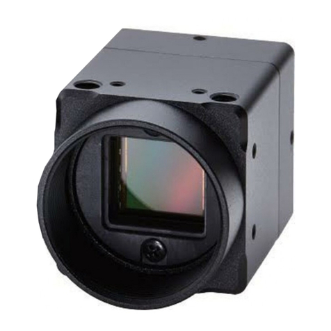
Sony Super HAD CCD SSC-DC314 User manual

COLOR VIDEO CAMERA
SSC-DC314
SSC-DC310P
SSC-DC318P
SERVICE MANUAL
1st Edition (Revised 1)

SSC-DC314/DC318P/DC310P (UC, CE)
!WARNING
This manual is intended for qualified service personnel only.
To reduce the risk of electric shock, fire or injury, do not perform any servicing other than that
contained in the operating instructions unless you are qualified to do so. Refer all servicing to
qualified service personnel.
!WARNUNG
Die Anleitung ist nur für qualifiziertes Fachpersonal bestimmt.
Alle Wartungsarbeiten dürfen nur von qualifiziertem Fachpersonal ausgeführt werden. Um die
Gefahr eines elektrischen Schlages, Feuergefahr und Verletzungen zu vermeiden, sind bei
Wartungsarbeiten strikt die Angaben in der Anleitung zu befolgen. Andere als die angegeben
Wartungsarbeiten dürfen nur von Personen ausgeführt werden, die eine spezielle Befähigung
dazu besitzen.
!AVERTISSEMENT
Ce manual est destiné uniquement aux personnes compétentes en charge de l’entretien.Afin
de réduire les risques de décharge électrique, d’incendie ou de blessure n’effectuer que les
réparations indiquées dans le mode d’emploi à moins d’être qualifié pour en effectuer d’autres.
Pour toute réparation faire appel à une personne compétente uniquement.

1
SSC-DC314/DC318P/DC310P (UC, CE)
Table of Contents
Manual Structure
Purpose of this manual .............................................................................................. 5
Related manuals......................................................................................................... 5
1. Operating Instructions
2. Service Overview
2-1. Removal of the Main Parts..........................................................................2-1
2-1-1. Front Block.................................................................................2-1
2-1-2. Filter Block.................................................................................2-2
2-2. Replacement of Power Cord (SSC-DC318P Only) ....................................2-2
3. Operating Description
3-1. BI-146 Board...............................................................................................3-1
3-2. MB-925 Board ............................................................................................3-1
3-3. PS-609 Board (For SSC-DC310P)..............................................................3-1
3-4. AC-207 Board (For SSC-DC314/DC318P) ................................................3-2
3-5. CT-215 Board..............................................................................................3-2
4. Adjustments
4-1. Preparations.................................................................................................4-1
4-1-1. Equipment Required...................................................................4-1
4-1-2. Connections for Adjustment ......................................................4-2
4-1-3. Adjustment Commander ............................................................4-2
4-1-4. Adjustmant Commander Relay Tool .........................................4-3
4-1-5. Chart to Select Items Requiring Adjustment .............................4-3
4-2. Adjustment Method.....................................................................................4-4
4-2-1. Preparations for Adjustment ......................................................4-4
4-2-2. Writing in Initial Data ................................................................4-4
4-3. Camera Adjustment.....................................................................................4-5
4-3-1. Setting up the Prepare for Adjustment Mode.............................4-5
4-3-2. INT VCXO Adjustment .............................................................4-5
4-3-3. SYNC Level Adjustment ...........................................................4-5
4-3-4. Burst Level Adjustment .............................................................4-5
4-3-5. SET UP Adjustment ...................................................................4-6
4-3-6. OB Level Adjustment ................................................................4-6

2SSC-DC314/DC318P/DC310P (UC, CE)
4-3-7. White Clip Level Adjustment ....................................................4-6
4-3-8. 0 dB Adjustment ........................................................................4-7
4-3-9. Y Level Adjustment ...................................................................4-7
4-3-10. AGC MAX Adjustment .............................................................4-8
4-3-11. Color Reproduction ....................................................................4-8
4-3-12. VCO Adjustment (SSC-DC314/DC318P) .................................4-9
4-3-13. Data Write ..................................................................................4-9
4-4. Checking After Adjustment ......................................................................4-10
4-4-1. Checking INT VCXO Adjustment ...........................................4-10
4-4-2. Checking SYNC Level Adjustment .........................................4-10
4-4-3. Checking Burst Level Adjustment ...........................................4-10
4-4-4. Checking SET UP Adjustment.................................................4-10
4-4-5. Checking White Clip Level Adjustment ..................................4-10
4-4-6. Checking 0 dB Adjustment ......................................................4-11
4-4-7. Checking Y Level Adjustment .................................................4-11
4-4-8. Checking AGC Adjustment .....................................................4-12
4-4-9. Checking Color Reproduction Adjustment ..............................4-12
4-4-10. Checking VCO Adjustment (SSC-DC314/DC318P)...............4-12
5. Spare Parts
5-1. Notes on Repair Parts..................................................................................5-1
5-2. Exploded View and Parts List.....................................................................5-2
5-2-1. SSC-DC314................................................................................5-2
5-2-2. SSC-DC318P..............................................................................5-4
5-2-3. SSC-DC310P..............................................................................5-6
5-3. Electrical Parts List .....................................................................................5-8
5-4. Packing Materials & Supplied Accessories ..............................................5-18
6. Semiconductor Pin Assignments
7. Block Diagrams
7-1. Board Location............................................................................................7-1
7-2. Overall Block Diagrams..............................................................................7-2

3
SSC-DC314/DC318P/DC310P (UC, CE)
8. Schematic Diagrams
Frame Wiring (SSC-DC314/DC318P)........................................................8-1
Frame Wiring (SSC-DC310P) ...................................................................8-2
AC-207 ........................................................................................................8-3
BI-146 .........................................................................................................8-3
CT-215 ........................................................................................................8-3
MB-925 .......................................................................................................8-5
PS-609 .........................................................................................................8-7
9. Board Layouts
AC-207 ........................................................................................................9-1
BI-146 .........................................................................................................9-2
CT-215 ........................................................................................................9-2
MB-925 .......................................................................................................9-3
PS-609 .........................................................................................................9-4


5
SSC-DC314/DC318P/DC310P (UC, CE)
Purpose of this manual This manual is the Service Manual of the color video camera SSC-DC314/DC310P/
DC318P.
This manual contains the operating instructions, service overview,
circuit descrip-
tion,
adjustments,
spare parts, semiconductor pin assignments, block diagrams,
schematic diagrams and board layouts.
Related manuals In addition to this Service Manual, the following manuals are provided for this unit.
..
..
.Operating Instructions
(Supplied with the SSC-DC314/DC310P/DC318P)
This manual is required for the proper operation and application of this unit.
Part of the Operating Instructions is included also in this Service Manual, in
Section 1, “Operating Instructions” .
Part number: 3-205-479-11
..
..
.“Semiconductor Pin Assignments” CD-ROM (Available on request)
This “Semiconductor Pin Assignments” CD-ROM allows you to search for
semiconductors used in B&P Company equipment.
Semiconductors that cannot be searched for on this CD-ROM are listed in the
service manual for the corresponding unit. The service manual contains a com-
plete list of all semiconductors and their ID Nos., and thus should be used together
with the CD-ROM.
Part number: 9-968-546-XX
Manual Structure


1-1
SSC-DC314/DC318P/DC310P (UC, CE)
Section 1
Operating Instructions Reprinted from the
operating instructions
3-205-479-11 (1)
Sony Corporation 2000
Printed in Japan
Owner’s Record
The model and serial numbers are located on the bottom.
Record these numbers in the spaces provided below.
Refer to these numbers whenever you call upon your Sony dealer
regarding this product.
Model No. Serial No.
Color Video Camera
Operating Instructions
Before operating the unit, please read these instructions
thoroughly and retain them for future reference.
Mode d’emploi
Avant de faire fonctionner cet appareil, lisez attentivement le
présent mode d’emploi et conservez-le pour toute référence
ultérieure.
Manual de instrucciones
Antes de utilizar la unidad, lea las instrucciones con atención y
consérvelas para su consulta en el futuro.
SSC-DC314
SSC-DC310P/DC318P
NOTICE FOR THE SSC-DC314
The graphical simbol is on the unit.
This symbol is intended to alert the user to the
presence of important operating and maintenance
(servicing) instructions in the literature accompanying
the appliance.
WARNING
To prevent fire or shock hazard, do not expose
the unit to rain or moisture.
To avoid electrical shock, do not open the cabi-
net. Refer servicing to qualified personnel only.
For the customers in the U.S.A. (SSC-DC314 only)
This equipment has been tested and found to comply with the limits for
a Class B digital device, pursuant to Part 15 of the FCC Rules. These
limits are designed to provide reasonable protection against harmful
interference in a residential installation. This equipment generates,
uses, and can radiate radio frequency energy and, if not installed
and used in accordance with the instructions, may cause harmful
interference to radio communications. However, there is no guarantee
that interference will not occur in a particular installation. If this equip-
ment does cause harmful interference to radio or television reception,
which can be determined by turning the equipment off and on, the user
is encouraged to try to correct the interference by one or more of the
following measures:
•Reorient or relocate the receiving antenna.
•Increase the separation between the equipment and receiver.
•Connect the equipment into an outlet on a circuit different from that to
which the receiver is connected.
•Consult the dealer or an experienced radio/TV technician for help.
You are cautioned that any changes or modifications not expressly
approved in this manual could void your authority to operate this
equipment.
The shielded interface cable recommended in this manual must be
used with this equipment in order to comply with the limits for a digital
device pursuant to Subpart B of Part 15 of FCC Rules.
AVERTISSEMENT
Afin d’éviter tout risque d’incendie ou d’electrocution, ne
pas exposer cet appareil àla pluie ou àl’humidité.
Afin d’écarter tout risque d’électrocution, garder le coffret
fermé. Ne confier l’entretien de l’appareil qu’à un personnel
qualifié.
ADVERTENCIA
Para evitar incendios o el riesgo de electrocución, no
exponga la unidad a la lluvia ni a la humedad.
Para evitar descargas eléctricas, no abra la caja.
En caso de avería, solicite asistencia técnica a personal
cualificado.
1-2 SSC-DC314/DC318P/DC310P (UC, CE)
English
Features
This SSC-DC314/DC310P/DC318P color video camera is equipped
with a 1/3 type Super HAD CCD®*(Super Hole-Accumulated-Diode
CCD) and also has the following features:
•High sensitivity (Minimum illumination: 1.5 lux, F 1.2)
•CCD-IRIS function
•Automatic white balance tracking and adjustment (ATW)
•DC controlled auto-iris lens capability
•Backlight compensation through the center measurement
•Can be operated via power multiplex or DC 12 V (SSC-DC310P)
•Line lock function (SSC-DC314: 60 Hz, SSC-DC318P: 50 Hz)
*Super HAD CCD®is registered trademark of Sony Corporation.
Notes on Use
Power supply
•The SSC-DC314 must always be operated with an AC 24 V (60 Hz)
power supply. In the U.S.A, use a Class 2 power supply which is UL
Listed. In Canada, use a CSA-certified Class 2 power supply.
–When connecting the transformer, be sure to connect each lead to
the appropriate terminal. Wrong connection may cause malfunction
and/or damage to the video camera.
–Ground the unit or an irregular voltage may be generated in the AC
power cord and may cause malfunction and/or damage to the video
camera.
•The SSC-DC310P must always be operated with a DC 12 V power
supply or the YS-W170P/W270P camera adaptor (not supplied).
•The SSC-DC318P must always be operated with an AC 230 V (50 Hz)
power supply.
Handling
Be careful not to spill water or other liquids on the unit, or allow
combustible or metallic objects to fall inside the body. If used with
foreign matter inside, the camera is liable to fail, or be a cause of fire or
electric shock.
Operation and storage locations
Avoid aiming the camera at very bright objects such as the sun or
electric lights for an extended period. Avoid operating or storing the unit
in the following locations.
•Extremely hot or cold places (operating temperature –10 °C to + 50 °C
(14 °F to 122 °F))
•Damp or dusty places
•Where it is exposed to rain
•Where it is subject to strong vibration
•Close to generators of powerful electromagnetic radiation such as
radio or TV transmitters.
•Where it is subject to fluorescent light reflections
•Where it is subject to unstable (flickering, etc.) lighting conditions.
Care of the unit
•Remove dust or dirt on the surface of the lens or CCD with a blower.
•Use a dry, soft cloth to clean the body. If it is very dirty, use a cloth
dampened with a small quantity of neutral detergent, then wipe dry.
•Avoid using volatile solvents such as thinners, alcohol, benzene, and
insecticides. They may damage the surface finish and/or impair the
operation of the camera.
Other
•When BLC is in the “ON”position, “hunting”may occur, that is, the
image may get darker and lighter as the camera “hunts”for the best
exposure level. If hunting occurs, set the BLC switch to “OFF.”
•If you use the CCD-IRIS function in locations where the camera is
exposed to fluorescent light, a slow color change may occur.
In the event of any problems with the operation of the camera, contact
your Sony dealer.

1-3
SSC-DC314/DC318P/DC310P (UC, CE)
SEE INSTRUCTION MANUAL
VIDEO LEVEL
DC IN/VD IN
VIDEO OUT MONITOR OUT
LH
DC
12V
BLC
CCD-IRIS
SHARP
OFF
OFF
NORM
SEE INSTRUCTION MANUAL
VIDEO LEVEL
VIDEO OUT
LH
V-PHASE
AC
24V
2
1
BLC
LL
CCD-IRIS
SHARP
OFF
INT
OFF
NORM
SEE INSTRUCTION MANUAL
VIDEO LEVEL
VIDEO OUT
LH
V-PHASE
BLC
LL
CCD-IRIS
SHARP
OFF
INT
OFF
NORM
LENS
COLORVIDEOCAMERA
Digital
B
A1
23
4
5
SSC-DC314
6
7
8
90 qa
qf
qh
SSC-DC318P
90 qa
qg
qh
9qa qs
qd
SSC-DC310P
Location and Function of Parts
Top/Front/Side Illustration
1Focal length adjustment ring
Use this ring to adjust the focal length (the distance between the lens
mounting plane and the image plane).
2Lens mount
Use to mount an appropriate CS-mount lens.
3Lens connector (4-pin socket)
Supplies power and control signals to an auto-iris lens (not supplied).
4Tripod adapter
The tripod adapter can be attached to either the top or bottom of the
camera using the four attached screws (1/4”UNC-20). On the SSC-
DC314, the tripod adapter is attached on top of the main body. On the
SSC-DC310P/DC318P, it is attached underneath the main body.
Rear
5SYNC switch (SSC-DC314/DC318P)
Use this switch to set the camera synchronization mode —internal
(INT) or line lock (L.L).
6BLC (backlight compensation) ON/OFF switch
When switched on, the backlight compensation function is enabled
through the center measurement. This function adjusts the exposure to
the optimal level according to the subject projected on the center of the
screen even when the image is lit from behind.
7CCD-IRIS ON/OFF switch
The electronic shutter adjusts the light quantity and the iris.
8Aperture switch
Set in the “SHARP”mode to sharpen the outline and produce a clearer
picture.
9Video level adjustment volume
Adjusts the signal level when DC control type auto-iris lens is in use.
q; V-PHASE (vertical phase) adjustment screw (SSC-DC314/
DC318P)
If you using SYNC switch 5in the L.L (Line Lock) mode, this screw
adjusts the vertical phase difference between this camera and another
camera.
qa VIDEO OUT (composite video signal output) connector (BNC
type) (SSC-DC314/DC318P)
qa DC IN (power input)/VD IN (external synchronization signal
input)/VIDEO OUT (composite video signal output) connector
(BNC type) (SSC-DC310P)
qs MONITOR OUT (monitor output) connector (BNC type)
(SSC-DC310P)
qd DC 12 V (power input) terminal (DC 12 V ±10%) (SSC-DC310P)
qf AC 24 V (power input) terminal (AC 24 V ±10%, 60 Hz)
(SSC-DC314)
qg Power cable (AC 230 V ±10%, 50 Hz) (SSC-DC318P)
qh UGround terminal (screw type) (SSC-DC314/DC318P)
If there are noises in the connections, connect this terminal to the
ground.
A
B

1-4 SSC-DC314/DC318P/DC310P (UC, CE)
C
D
1
2
E
1
5
2
3
4
6
7
8
4
1
2
3
LENS
COLORVIDEOCAMERA
Digital
Installation
Suitable lens
The lens must be a CS-mount type of less than 1 kg. The protrusion
behind the mounting surface must be within the following limits:
1CS-mount lens
24 mm or less
Changing the plug on an auto-iris lens cable
The camera is supplied with a plug to fit the LENS connector. To
connect an auto-iris lens, first replace the plug on the lens cable with
the supplied plug.
1
Detach the old plug from the lens cable.
2
Solder the lens cable to the pins of the supplied plug. (For cable pin
assignment, refer to the instruction manual for the lens.)
1Cover
2Lens cable
3Rib (If the cable is thick, cut this off.)
4Plug (unit accessory)
5Pin 4 DRV –
6Pin 2 CONT +
7Pin 1 CONT –
8Pin 3 DRV +
Fitting the lens
1
Unscrew the lens mount cap.
2
Screw in the lens, and turn it until it is secured.
3
Insert the lens plug in the LENS connector.
When fitting a manual-iris lens, omit step 3.
4
Adjust the focal length by turning the adjustment ring.
Caution
Keep the lens mount cap on the camera when not attaching a lens.
C
D
E

1-5
SSC-DC314/DC318P/DC310P (UC, CE)
SEE INSTRUCTION MANUAL
VIDEO LEVEL
DC IN/VD IN
VIDEO OUT MONITOR OUT
LH
DC
12V
BLC
CCD-IRIS
SHARP
OFF
OFF
NORM
G
H
F
2
8
7
9
5
1
3
2
14
5
36
SEE INSTRUCTION MANUAL
VIDEO LEVEL
DC IN/VD IN
VIDEO OUT MONITOR OUT
LH
DC
12V
BLC
CCD-IRIS
SHARP
OFF
OFF
NORM
SEE INSTRUCTION MANUAL
VIDEO LEVEL
VIDEO OUT
LH
V-PHASE
AC
24V
2
1
BLC
LL
CCD-IRIS
SHARP
OFF
INT
OFF
NORM
SEE INSTRUCTION MANUAL
VIDEO LEVEL
VIDEO OUT
LH
V-PHASE
BLC
LL
CCD-IRIS
SHARP
OFF
INT
OFF
NORM
4
5
6
7
8
1
3
4
5
6
7
1
3
2
SSC-DC314
SSC-DC318P
SSC-DC310P
SSC-DC310P
6
7
0
4
Connecting the SSC-DC310P
Using a DC 12 V power supply
1SSC-DC310P (rear) 5Power supply
2VIDEO OUT connector 6+12 V
375-ohm coaxial cable 7GND (ground)
4VIDEO INPUT connector
Note
To prevent short circuits, do not let the exposed ends of the main lead
wires touch each other when connecting to the main lead terminals.
Using a YS-W170P/W270P camera adapter
(not supplied) (Power multiplex)
1SSC-DC310P (rear) 6YS-W170P/W270P
2DC IN. VD IN/VIDEO OUT camera adapter (rear)
connector 7VIDEO OUT connector
3CAMERA IN connector 8VIDEO INPUT connector
4MONITOR OUT connector (monitor input connector)
5VIDEO INPUT connector 9Portable monitor
075-ohm coaxial cable
(Less than DCR 30 Ω/300 m)
Connecting the SSC-DC314/DC318P
Connect the power cable after connecting the auto-iris lens, video
output, and external synchronization input connector.
Using an internal synchronization signal.
1SSC-DC314/DC318P (rear)
2Set the SYNC switch to INT (internal synchronization).
3Connect to the VIDEO OUT connector.
475-ohm coaxial cable
5Connect to the VIDEO IN connector on a video monitor, etc.
6To power supply (AC 24 V) (SSC-DC314) /to a wall outlet (AC 230
V) (SSC-DC318P)
7Power cord
8To AC 24 V terminals 1 and 2 (SSC-DC314)
When using an external (L.L) synchronization signal, set the SYNC
switch 2to L.L and make connections as above.
Note
The line lock is available only in areas with the following power
frequencies:
SSC-DC314 60 Hz
SSC-DC318P 50 Hz
F
G
H

1-6 SSC-DC314/DC318P/DC310P (UC, CE)
I
J
12
3
4
Phase Adjustment
If you connect multiple cameras to the camera switcher, lock each
camera output to the AC line phase. (The phase is adjusted when the
camera is operated in the line lock mode.)
1Camera switcher
I
2Monitor
3Vertical phase
4Adjustable range
Vertical phase: The image may be shifted up/down in the line lock
mode, depending on the camera’s power line system.
Adjust the image by watching the monitor and turning the V-PHASE
adjustment screw.
CCD Characteristics
The following conditions may be observed when using a CCD camera.
They are not due to any fault within the camera.
Vertical smear
This phenomenon occurs when viewing a very bright object.
Patterned noise
This is a fixed pattern that may appear over the entire monitor screen
when the camera is operated at high temperatures.
Jagged picture
When viewing stripes, straight lines, or similar patterns, the image on
the screen may appear jagged.
Specifications
Image device 1/3type interline transfer CCD
Effective picture elements SSC-DC314: 768 (horizontal) ×494
(vertical)
SSC-DC310P/DC318P: 752 (horizontal) ×
582 (vertical)
Lens mount CS-mount
Signal system SSC-DC314: NTSC color system
SSC-DC310P/DC318P: PAL color system
Synchronization system SSC-DC314/DC318P: internal/line lock
SSC-DC310P: internal/external (VD Lock
switched automatically)
Horizontal resolution 480 lines
Minimum illumination 1.5 lux, F 1.2
Video output 1 Vp-p, 75 ohms, negative sync
Video S/N 50 dB (with AGC set to OFF)
White balance ATW only
Automatic gain control (AGC) Always ON
Power requirements SSC-DC314: AC 24 V (60 Hz)
SSC-DC310P:
DC 12 V for power source: DC 12V ±10%
When YS-W170P/W270P is in use:
DC 24 V ±5 V
SSC-DC318P: AC 230 V (50 Hz)
Power consumption SSC-DC314/DC318P: 3.5 W
SSC-DC310P:
DC 12 V for power source: 2.5 W
When YS-W170P/W270P is in use: 3.0 W
Operating temperature –10 °C to +50 °C (14 °F to 122 °F)
Operating humidity 20 to 80%
Storage temperature –40 °C to +60 °C (–40 °F to 140 °F)
Storage humidity 20 to 95%
Shock resistance 70 G
Mass SSC-DC314: 560 g (1 lb 4 oz)
SSC-DC310P: 440 g (16 oz)
SSC-DC318P: 640 g (1 lb 7 oz)
Dimensions 70 ×57 ×129 (w/h/d) mm
(2
7
/
8
×2
1
/
4
×5
1
/
8
inches)
Supplied accessories 4-pin plug for auto iris lens (1)
C-mount adapter (1)
Design and specifications are subject to change without notice.
J

2-1
SSC-DC314/DC318P/DC310P (UC, CE)
Section 2
Service Overview
2-1. Removal of the Main Parts
2-1-1. Front Block
4B2 x4
1B2 x4
1B2 x4
1B2 x4
1B2 x4
5B2 x4
2Case, upper
3Flat cable
MB-925 board
6Front block

2-2 SSC-DC314/DC318P/DC310P (UC, CE)
2-1-2. Filter Block
2B2 x4
3Ring base
4Ring
5Filter block ass
y
Spring,compressio
Front panel
Front chassis
*A
1B2 x4
*A
Plate, click
2-2. Replacement of Power Cord (SSC-DC318P Only)
When replacing the power cord, use a new cord clamper and secure the clamper onto the cord with a pair
of pliers first, and then attach the rear panel.
Cord clamper
35 mm
Pliers
Cord

3-1
SSC-DC314/DC318P/DC310P (UC, CE)
Section 3
Operating Description
3-1. BI-146 Board
The signal output (IC101, pin 8) from the self-bias type
CCD imager (IC101) passes through the output buffer
(Q101), and is sent to the MB-925 board via CN101,
pin12. H1, H2 and V1, V2, V3, V4 pulses are CCD drive
pulses supplied from the MB-925 board.
3-2. MB-925 Board
This board is a main board of the unit that performs the
digital signal processing of the camera signal using DSP.
Then it produces the video signal output.
(1) CCD Drive Pulse
The CCD drive pulses generated in DSP (IC305) are sent
to CN302 passes through the level converter IC (IC303).
These pulses are fitted to the CCD drive potential by PG,
H1 and H2 pulses. Remaining pulses that V1, V2, V3, V4
and VSUB are also sent to CN302 passes through the V
drive pulses driver (IC302).
(2) Signal Processor
The CCD-OUT signal (CN302, pin 12) from the BI-146
board is supplied to pin 39 of the CDS/AGC IC (IC201).
After it is subjected to the correlative double sampling
(CDS), the output is produced to pin 21 of IC201 via AGC
amplifier, black clamp and sub amplifier (at 0 dB). And
this output signal is sent to the incorporated 9 bits A/D
converter (IC305, pin 64) of the DSP, then it is performed
the digital signal processing. The component signal is
produced passes through incorporated A/D converter of the
DSP after it has performed the digital signal processing. Y
and synchronizing signals from pin 46 of the DSP (IC305)
are sent passes through the LPF (FL502). C signal from
pin53 of the DSP (IC305) is sent passes through the BPF
(FL501), and it is mixed to Y and synchronizing signals
within adder circuit, then it becomes composite signal.
Further, this composite signal is sent passes through the
video amplifier [ IC501 (For SSC-DC314/DC318P), IC701
in the PS-609 board (For SSC-DC310P)].
(3) External Synchronizing Signal
For SSC-DC314/DC318P
During line locked mode (LL mode), the V pulse from
CN501, pin 3 is supplied to pin 31 of the DSP (IC305)
passes through the phase shift and wave shaping circuit
(IC601). The internal VD and phase compared signal are
sent from pin 34 of the DSP (IC305), and is supplied to the
VCO circuits (IC401 and IC402) passes through the LPF
(Q303), then it is controlled to the prescribed oscillation
frequency. This controlled signal is sent back to pin 97 of
the DSP (IC305) as a reference clock signal.
For SSC-DC310P
During VD mode, VD signal from the power supply
multiple line is supplied to pin 32 of the DSP (IC305) after
separated it in IC607. This input signal is discriminated
automatically by DSP (IC305) and then selected to the VD
mode. The internal VD and phase compared signal are
produced to pin 34 of the DSP (IC305) and are sent to the
DSP (IC305, pin 42) passes through the LPF (Q303), then
it is controlled to the prescribed oscillation frequency.
3-3. PS-609 Board (For SSC-DC310P)
(1) Power Supply Circuit
The power supply voltages +3.3V, +5V, +15V and _7V
required in each board, are produced from DC power
supply circuit separated from DC 12 V or power supply
multiple line passes through the DC-DC converter (IC705
peripheral circuit).
(2) Multiplex Circuit
At the same time, this circuit is multiplied the camera
video signal to the power supply multiple line (CN703, pin
2), DC supply voltage drawn by the LPF make up Q710
and is supplied to the power supply circuit. Also, the
multiplex synchronizing signal (VD) drawn by the differ-
ential amplifier (Q709) and is sent to the VD separation
circuit of the MB-925 board via CN701, pin 3.

3-2 SSC-DC314/DC318P/DC310P (UC, CE)
3-4. AC-207 Board
(For SSC-DC314/DC318P)
This board is converted the AC source input to the pre-
scribed voltage via the insulation transformer (T801), and
+3.3V, +5V, +15V and _7V voltages are produced that
required in the DC-DC converter (DD801).
3-5. CT-215 Board
This board is arranged in all input/output terminals and
user control switch that is selected of the camera functions.
It is also arranged the Line Lock V Phase adjustment (For
SSC-DC314/DC318P) and the DC Servo Lens Level
adjustment control volumes.

4-1
SSC-DC314/DC318P/DC310P (UC, CE)
Section 4
Adjustments
J-6029-140-B Pattern box PTB-500
J-6432-400-A Vectorscope scale
J-6432-310-A
Adjustment commander relay tool
.Light source for test chart
.For color adjustment
This scale is printed on the back cover.
J-6020-250-A Color-bar chart
J-6082-053-B Camera adjustment commander
.For color adjustment
.RM-95 partly converted
WGC
Y
YI M
g
RB
J-6431-850-A Pattern box PTB-700
CB
WB B-Y
R-Y
MG
R
Y
L
G
B
C
Y
4-1. Preparations
4-1-1. Equipment Required
.ND filter
ND 25 (25 %) 50 by 50 mm square (Kenko) : 2PCS
ND 50 (50 %) 50 by 50 mm square (Kenko) : 1PC
*Make the transmission factor to 3.125 % with triple
ND filter
.Oscilloscope
.Digital voltmeter
.Vectorscope
.Waveform monitor
.Color monitor
.Frequency counter

4-2 SSC-DC314/DC318P/DC310P (UC, CE)
Pattern box
(PTB-500) CAMERA
SSC-DC310P
Waveform monitor
Adjustment
commander
(J-6082-053-B)
Relay tool
(J-6432-310-A)
CN103
MB board
CN301
MONITOR
OUT
CN104
Oscilloscope
Power supply
SSC-DC310P:
DC 12V
SSC-DC314:
AC 24V 60 Hz
SSC-DC318P:
AC 230V 50 Hz
Color monitor
75Ztermination
Vectorscope
DC IN. VD IN. VIDEO OUT
YS-W170P/W270P(PAL)
Display Data Display Mode
LCD display of remote control for adjustment
HOLD
WIDE
ZOOM
TELE
START/
STOP
REC
REVIEW FOCUS
POWER
AUTO/MAN
EDIT SEARCH
COUNTER
RESET DISPLAY FRAME SLOW
REC PAUSE
REW PB FF
STOP
Remote control for adjustment
RM-95 (J-6082-053-B)
Slide
switch INITIAL DATA
write button
STEP FORWARD
button
STEP REVERSE
button
DATA write button
DISPLAY MODE
UP button
ADJUSTMENT MODE
SETTING button
RM-95
DATA UP
button
(Simultaneity push)
DATA DOWN
button
DISPLAY MODE
DOWN button
MODE
DISPLAY
CHANGE
button
CHANGE
DATA button
4-1-2. Connections for Adjustment 4-1-3. Adjustment Commander
Other manuals for Super HAD CCD SSC-DC314
1
This manual suits for next models
2
Table of contents
Other Sony CCTV Camera manuals

Sony
Sony HDC-750A User manual

Sony
Sony FCB-CX12E User manual

Sony
Sony HDC1000 series User manual

Sony
Sony HDC-900 Series User manual

Sony
Sony HDC5500 User manual

Sony
Sony KDP-673SH20 User manual

Sony
Sony super motion hdc4300 User manual

Sony
Sony FCBEH6300 User manual

Sony
Sony FCB-EX2400 User manual

Sony
Sony HDC5500 User manual
Popular CCTV Camera manuals by other brands

Novus
Novus NVAHD-1DN3102H/IR-1 user manual

Hitachi Kokusai Electric
Hitachi Kokusai Electric SK-HD1200 operating instructions

IAI
IAI LQ-401CL user manual

CIS
CIS VCC-F32U29CL Product specification & operation manual

HIK VISION
HIK VISION DS-2CC1172P Technical manual

Omron
Omron SENTECH STC-HD133 Series user guide