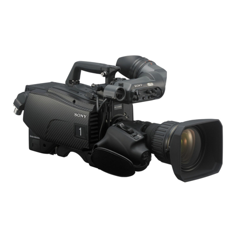
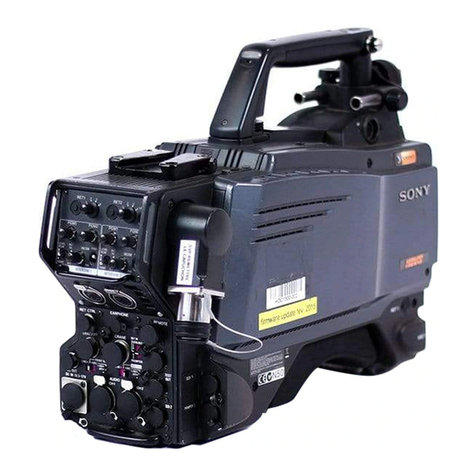
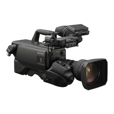
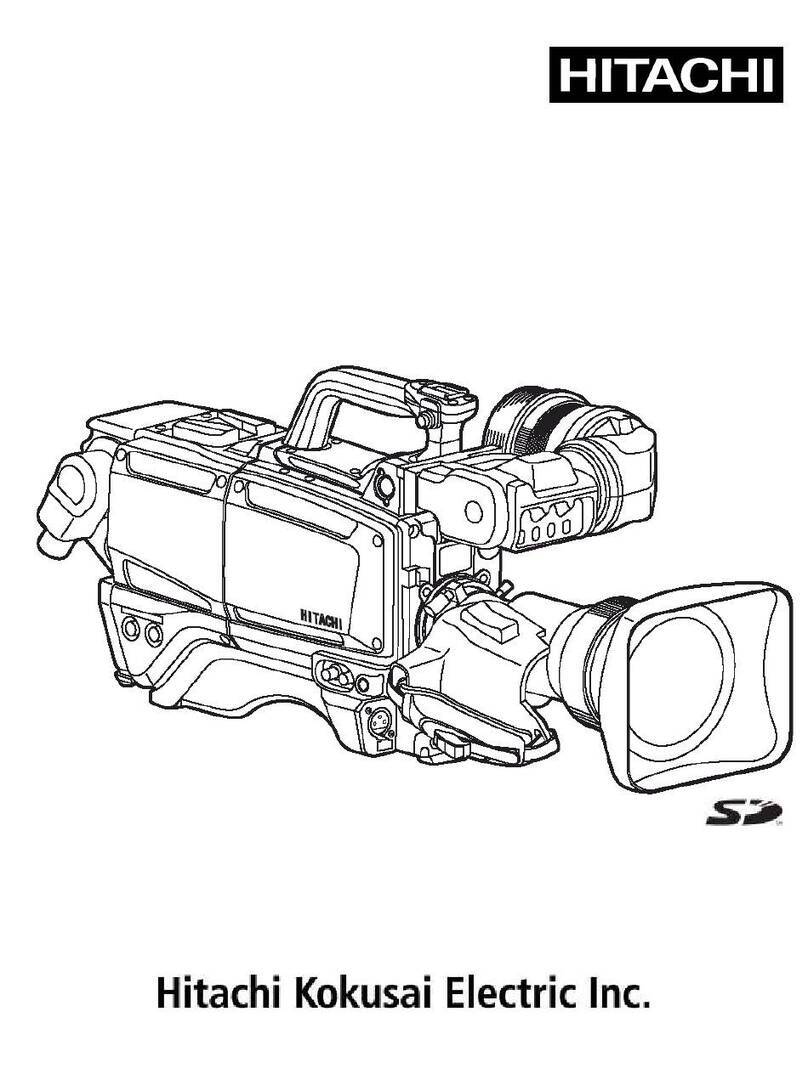
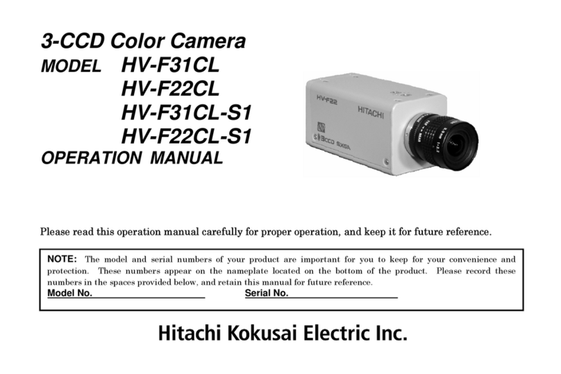
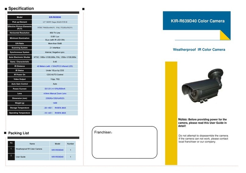
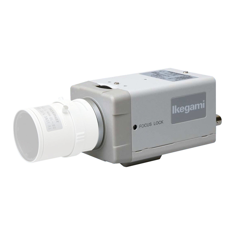
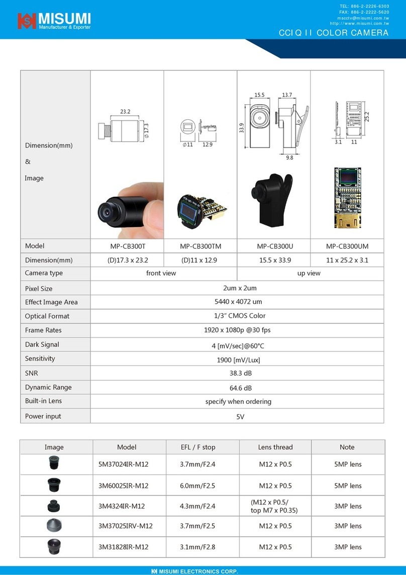
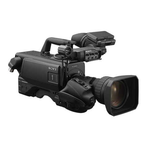
Sony HDC-750A User manual

HD COLOR CAMERA
HDC-750A
MAINTENANCE MANUAL
Volume 1 1st Edition
Serial No. 10001 and Higher

!WARNING
This manual is intended for qualified service personnel only.
To reduce the risk of electric shock, fire or injury, do not perform any servicing other than that
contained in the operating instructions unless you are qualified to do so. Refer all servicing to
qualified service personnel.
!WARNUNG
DieAnleitung ist nur für qualifiziertes Fachpersonal bestimmt.
Alle Wartungsarbeiten dürfen nur von qualifiziertem Fachpersonal ausgeführt werden. Um die
Gefahr eines elektrischen Schlages, Feuergefahr und Verletzungen zu vermeiden, sind bei
Wartungsarbeiten strikt dieAngaben in der Anleitung zu befolgen. Andere als die angegeben
Wartungsarbeiten dürfen nur von Personen ausgeführt werden, die eine spezielle Befähigung
dazu besitzen.
!AVERTISSEMENT
Ce manual est destiné uniquement aux personnes compétentes en charge de l’entretien.Afin
de réduire les risques de décharge électrique, d’incendie ou de blessure n’effectuer que les
réparations indiquées dans le mode d’emploi à moins d’être qualifié pour en effectuer d’autres.
Pour toute réparation faire appel à une personne compétente uniquement.

1 (E)
HDC-750A
Table of Contents
Manual Structure
Purpose of this manual ........................................................................................ 5 (E)
Contents ............................................................................................................... 5 (E)
Relative manual ................................................................................................... 6 (E)
1. Installation
1-1. Supplied Accessories ............................................................................1-1 (E)
1-2. Connectors and Cables..........................................................................1-1 (E)
1-2-1. Connector Input/Output Signals...........................................1-1 (E)
1-2-2. Connection Connectors ........................................................1-4 (E)
1-3. Operating Environment.........................................................................1-4 (E)
1-4. Function of Internal Switches ...............................................................1-5 (E)
1-5. Example of System Configuration ........................................................1-6 (E)
2. Service Overview
2-1. Notes on Service ...................................................................................2-1 (E)
2-1-1. Extension Board ...................................................................2-1 (E)
2-1-2. Notes on Repair Parts...........................................................2-1 (E)
2-2. Location of Printed Circuit Boards .......................................................2-1 (E)
2-3. Removal of Cabinet...............................................................................2-2 (E)
2-4. Circuit Description ................................................................................2-3 (E)
2-5. Disconnecting/Connecting Flexible Card Wire ....................................2-5 (E)
2-6. Positioning Adjustment for Filter Knobs ..............................................2-5 (E)
2-7. Replacement of CCD Unit ....................................................................2-6 (E)
2-7-1. Description on CCD Block Number ....................................2-6 (E)
2-7-2. Replacement of CCD Unit ...................................................2-6 (E)
2-8. Replacement of Filter Disk Unit ...........................................................2-7 (E)
2-8-1. Filter Disk Unit ....................................................................2-7 (E)
2-8-2. ND/CC Filters ......................................................................2-8 (E)
2-8-3. Driver board .........................................................................2-9 (E)
2-9. Replacement of DC/DC Converter Unit ...............................................2-9 (E)
2-10. Replacement of Circuit Board.............................................................2-11 (E)
2-10-1. Note on Replacement of Parts in RP-108 and
NR-66 Boards.....................................................................2-11 (E)
2-10-2. Description on EEPROM Data ..........................................2-11 (E)
2-10-3. Adjustment after Replacement of Board............................2-11 (E)
2-10-4. Replacement of IF-569 Board ............................................2-11 (E)
2-10-5. Replacement of MB-570 Board .........................................2-12 (E)
2-11. Replacement of Fan.............................................................................2-13 (E)

2 (E) HDC-750A
2-12. Replacement of Connector ..................................................................2-14 (E)
2-12-1. 68-pin Connector ................................................................2-14 (E)
2-12-2. VF Connector .....................................................................2-14 (E)
2-12-3. MIC Connector...................................................................2-14 (E)
2-12-4. TEST OUT Connector .......................................................2-15 (E)
2-13. Replacement of Function Switches .....................................................2-16 (E)
2-13-1. On the Side Switch Panel ...................................................2-16 (E)
2-13-2. On the Front Switch Panel .................................................2-16 (E)
2-13-3. On the Top Panel ................................................................2-17 (E)
2-14. Periodic Replacement Part ..................................................................2-18 (E)
2-15. Cleaning of Dustproof Filter ...............................................................2-19 (E)
2-16. Cares After Using at Special Environment .........................................2-19 (E)
2-17. Note on Replacement of Lithium Battery ...........................................2-19 (E)
3. Setup Menu
3-1. Setup Menu ...........................................................................................3-1 (E)
3-1-1. Operation Menu ...................................................................3-3 (E)
3-1-2. Paint Menu ...........................................................................3-7 (E)
3-1-3. Maintenance Menu .............................................................3-11 (E)
3-1-4. File Menu ...........................................................................3-14 (E)
3-1-5. Diag Disp Menu .................................................................3-15 (E)
3-1-6. SYS Config Menu ..............................................................3-16 (E)
4. Electrical Alignment
4-1. Preparation ............................................................................................4-1 (E)
4-1-1. Equipment Required.............................................................4-1 (E)
4-1-2. Notes on Adjustment ............................................................4-1 (E)
4-1-3. Connection ...........................................................................4-2 (E)
4-1-4. Initial Settings ......................................................................4-3 (E)
4-2. Filter Drive Board Adjustment..............................................................4-3 (E)
4-2-1. Filter Positioning Adjustment ..............................................4-3 (E)
4-3. VA-158 Board Adjustment ...................................................................4-4 (E)
4-3-1. TEST SAW Level Adjustment.............................................4-4 (E)
4-3-2. VA Gain Adjustment............................................................4-5 (E)
4-4. MX-59 Board Adjustment.....................................................................4-6 (E)
4-4-1. FLARE PRESET Adjustment ..............................................4-6 (E)
4-4-2. RGB Level Adjustment ........................................................4-7 (E)
4-4-3. Knee Aperture Crispening Adjustment ................................4-7 (E)
4-4-4. Knee Aperture Balance Adjustment.....................................4-8 (E)
4-4-5. Pedestal Level Adjustment ...................................................4-8 (E)
3 (E)
HDC-750A
4-5. PR-200 Board Adjustment ..................................................................4-10 (E)
4-5-1. Settings of Input Level .......................................................4-10 (E)
4-5-2. Gamma Balance Adjustment..............................................4-11 (E)
4-6. IE-44 Board Adjustment .....................................................................4-11 (E)
4-6-1. Settings of Input Level .......................................................4-12 (E)
4-6-2. Video Level Adjustment ....................................................4-12 (E)
4-6-3. Color-bar Level Adjustment ..............................................4-13 (E)
4-6-4. DTL Balance Adjustment ..................................................4-13 (E)
4-7. Overall Video Adjustment ..................................................................4-14 (E)
4-7-1. VA Gain Adjustment..........................................................4-14 (E)
4-7-2. White Shading Adjustment ................................................4-14 (E)
4-7-3. Black Shading Adjustment.................................................4-16 (E)
4-7-4. Flare Adjustment ................................................................4-16 (E)
4-7-5. Check of Gamma Balance..................................................4-17 (E)
4-7-6. Gamma Correction Adjustment .........................................4-18 (E)
4-7-7. Knee Point .Knee Slope Adjustment ................................4-18 (E)
4-7-8. White Clip Level Adjustment ............................................4-19 (E)
4-7-9. H/V Ratio Adjustment........................................................4-20 (E)
4-7-10. Detail Level Adjustment ....................................................4-21 (E)
4-7-11. Crispening Adjustment.......................................................4-21 (E)
4-7-12. Level Dependent Adjustment.............................................4-22 (E)
4-7-13. Detail Frequency Adjustment ............................................4-22 (E)
4-7-14. Detail Clip Adjustment ......................................................4-23 (E)
4-7-15. Auto-iris Adjustment..........................................................4-24 (E)
4-7-16. File Store ............................................................................4-25 (E)
4-8. Adjustment After Replacement of ND Filter ......................................4-26 (E)
http://getMANUAL.com


5 (E)
HDC-750A
Purpose of this manual This manual is the maintenance manual for HD Color Camera HDC-750A.
This manual describes the information items necessary when the unit is supplied and
installed, items that premise the service based on the components parts such as
alignment, schematic diagrams, board layouts and spare parts lists, assuming use of
system and service engineers.
Contents The following are summaries of all the sections for understanding the contents of
this manual.
Section 1 Installation
Describes information about connector input/output signals, instance of system
configuration and function of internal switches.
Section 2 Service Overview
Describes location of printed circuit board, circuit description, replacement of parts
and notes on service.
Section 3 Setup Menu
Describes setup menu of the camera and self-diagnosis.
Section 4 Electrical Alignment
Describes the general information for electrical adjustment and the adjustment
procedure of this unit.
Section 1 Spare Parts
Describes exploded views, parts list, supplied accessories and optional fixtures used
in the unit.
Section 2 Semiconductor Pin Assignments
Describes function diagrams and pin names of semiconductor used in the unit.
Section 3 Block Diagrams
Describes overall block diagram and block diagrams for every circuit board.
Section 4 Schematic Diagrams
Describes schematic diagrams for every circuit board and frame wiring.
Section 5 Board Layouts
Describes board layouts for every circuit board.
Manual Structure
Maintenance Manual
Volume 1
Maintenance Manual
Volume 2

6 (E) HDC-750A
Relative manual Besides this maintenance manual the following manual is available for this unit.
..
..
.Operation Manual (Supplied with this unit)
This manual is necessary for application and operation of this unit.

1-1 (E)
HDC-750A
(EXTERNAL VIEW)
Section 1
Installation
1-1. Supplied Accessories
Accessories Sony P/N Q’ty
Shoulder belt A-6772-374-A 1
Tripod adaptor VCT-14 ––––––––––– 1
Extension board EX-512 A-8273-247-A 1
Operation manual ––––––––––– 1
Maintenance manuals Vol.1, Vol.2 ––––––––––– 1 each
1-2. Connectors and Cables
1-2-1. Connector Input/Output Signals
Output Signal
.TEST OUT
BNC type 75 Z, 1.0 Vp-p
MIC IN (3P FEMALE)
No. Signal I/O Specifications
1 MIC (G) —— _60 dBu High impedance
2 MIC (X) IN Balanced
3 MIC (Y) IN
(0 dBu = 0.775 Vrms)

1-2 (E) HDC-750A
(EXTERNAL VIEW)
(EXTERNAL VIEW)
LENS (12P FEMALE)
No. Signal I/O Specifications
1 RET VIDEO IN ENABLE: 0 V
ENABLE DISABLE: +5 V or OPEN
2 VTR START IN ENABLE: 0 V
/STOP DISABLE: +5 V or OPEN
3 GND GND for UNREG
4 AUTO SERVO OUT AUTO: +5 V
MANU: 0 V or OPEN
5 IRIS CONT OUT +3.4 V (F16) to
+6.2 V (F2.8)
6 UNREG OUT +10.5 V to +17 V
7 IRIS POSITION IN +3.4 V (F16) to
+6.2 V (F2.8)
8 AUTO/MANU OUT AUTO IRIS: 0 V
MANUAL IRIS: +5 V
9 EXTENDER IN EX 2 ON: 0 V
ON/OFF EX 0.8 ON: +3.8 V
OFF: +4.8 V
10 ZOOM IN WIDE: 2 V
POSITION TELE: 7 V
11 FOCUS POSI IN ∞:7V
min.: 2 V
12 LENS TX OUT Serial data for HKCA-700
VF (20P FEMALE)
No. Signal I/O Specifications
1 S-DA TA IN/OUT TTL level
2 NC No connection
3 POWER OUT ON: OPEN
OFF CTL OFF: GND
4 SCK OUT TTL level
5 COLOR/BW IN B/W: GND
COLOR: OPEN
6 NC No connection
7 NC No connection
8 G TALLY OUT ON: 5 V
OFF: GND
9 PEAKING IN VF to CAM, Zi = 1 k Z
CTL 0 V to 5 V
0 V: PEAKING OFF
5 V: PEAKING MAX
10 NC No connection
11 NC No connection
12 Y VIDEO OUT 1.0 V p-p, Zo = 75 Z
13 VIDEO GND —— GND for VIDEO
14 NC No connection
15 NC No connection
16 NC No connection
17 R TALLY OUT ON: 5 V
OFF: GND
18 NC No connection
19 UNREG GND —— GND for UNREG
20 UNREG OUT +10.5 V to +17 V
1-2. Connectors and Cables

1-3 (E)
HDC-750A
34
68
1
35
(EXTERNAL VIEW)
CA (68P FEMALE)
No. Signal I/O Specifications
1 UNREG (G) —— GND for UNREG
2 UNREG (G) ——
3 VF UNREG (G) —— GND for VF UNREG
4 LENS UNREG (G) —— GND for LENS UNREG
5 UNREG IN +10.5 to +17.0 V
6 UNREG IN
7 VF UNREG IN +10.5 to +17.0 V
8 LENS UNREG IN +10.5 to +17.0 V
9 SCL (CHU) IN/OUT IIC interface, 5 Vp-p
10 SDA (CHU) IN/OUT IIC interface, 5 Vp-p
11 RM RX DATA (X) IN New command interface
12 RM TX DATA (Y) OUT
13 RM DATA IN/OUT GND for RM DATA
14 CHU POWER SAVE IN 0 V: SAVE
15 ADP SYNC GND —— GND for SYNC
16 ADP SYNC IN Negative pulse, 5 Vp-p
17 NC No connection
18 VF VIDEO (Y) IN WPL*1: 0.7 V, 0 Vdc,
Zi = 75 Z
19 VF VIDEO (PB)IN PL
*2
: ±0.35 V, 0 Vdc,
Zi = 75 Z
20 VF DTL OUT Negative DTL
21 TEST GND —— GND for TEST
22 NC No connection
23 +5.5 V (CHU) OUT
24 GND (CHU) ——
25 _5.5 V (CHU) OUT
26 NC No connection
27 R CHU VIDEO OUT 0.7 V, 0 Vdc, Zo = 75 Z
28 NC No connection
29 G CHU VIDEO OUT 0.7 V, 0 Vdc, Zo = 75 Z
30 NC No connection
31 B CHU VIDEO 0.7 V, 0 Vdc, Zo = 75 Z
32 NC No connection
33 MIC GND —— GND for MIC
34 MIC (X) OUT _60 dBu, Balanced
*1 WPL: White peak level
*2 PL: Peak level
No. Signal I/O Specifications
35 UNREG (G) —— GND for UNREG
36 UNREG (G) ——
37 VF UNREG (G) —— GND for VF UNREG
38 LENS UNREG (G) —— GND for LENS UNREG
39 UNREG IN +10.5 to +17.0 V
40 UNREG IN
41 VF UNREG IN +10.5 to +17.0 V
42 LENS UNREG IN +10.5 to +17.0 V
43 SCL (ADP) IN/OUT IIC interface, 5 Vp-p
44 SDA (ADP) IN/OUT IIC interface, 5 Vp-p
45 RM RX DATA (Y) IN New command interface
46 RM TX DATA (X) OUT
47 VTR SAVE OUT 0 V: SAVE
48 VF POWER SAVE IN 0 V: SAVE
49 SKIN MARKER IN ON: +5 V
OFF: 0 V
50 AUTO MARKER OUT ON: +5 V
OFF: 0 V
51 CHU POWER SAVE OUT 0 V: SAVE
52 VF VIDEO (Y) GND IN GND for VF VIDEO(Y)
53 VF VIDEO (PR)IN PL
*2
: ±0.35 V, 0 Vdc,
Zi = 75 Z
54 VF VIDEO (PBPR) —— GND for VF VIDEO
GND (PBPR)
55 TEST IN 0.7 V, 0 Vdc, Zi = 75 Z
56 NC No connection
57 UNREG (+) SENSE IN
58 UNREG (_) SENSE IN
59 NC No connection
60 NC No connection
61 R CHU VIDEO GND —— GND for R CHU VIDEO
62 NC No connection
63 G CHU VIDEO GND —— GND for G CHU VIDEO
64 NC No connection
65 B CHU VIDEO GND —— GND for B CHU VIDEO
66 CHU SEPARATE IN 0V: SEPARATE
67 NC No connection
68 MIC (Y) OUT _60 dBu, Balanced
(0 dBu = 0.775 Vrms)
1-2. Connectors and Cables

1-4 (E) HDC-750A
1-2-2. Connection Connectors
Connection made with the connector panels during instal-
lation or service, should be made with the connectors/
complete cable assemblies specified in the following list,
or equivalent parts.
Indication Connection connector/cable
TEST OUT 1-569-370-12 Plug, BNC or
(BNC) B-B Cable assembly (1.5 m, Option)
MIC 1-508-084-00 XLR, 3P Male or
(3P FEMALE) ITT Cannon XLR-3-12C equivalent
1-3. Operating Environment
Operating Temperature: _20 dC to +45 dC
Storage Temperature: _20 dC to +50 dC
Humidity: No condensation
.Install the unit in a location as dry and well-ventilated as
possible.
.Do not install the unit in the following conditions.
High temperature room or near the heat source.
Excessive dust or mechanical vibration.
Intense magnetic and electric fields.
A place subjected to direct sunlight or strong light.
1-2. Connectors and Cables
1-3. Operating Environment

1-5 (E)
HDC-750A
S1
DRIVER BOARD (A SIDE)
REMOTE
LOCAL
3
C
IF-569 BOARD (A SIDE)
B
A
D
E
F
G
H
4521
S1
Driver Board
S1: REMOTE/LOCAL switch
REMOTE: Filter (CC or ND) can be selected by using the
HDCU, MSU and RCP and so on.
LOCAL: Filter (CC or ND) can be selected with the
knob on the front panel.
Factory-set position: REMOTE
1-4. Function of Internal Switches
IF-569 Board
S1
S1-1: Factory-use switch
Always set to OFF.
Factory-set position: OFF
S1-2: Selection of HDC-700A and HDC-750A
ON: HDC-700A
OFF: HDC-750A
Factory-set position: OFF
n
In replacing the IF-569 board, be sure to set the switch
S1-2 to the proper position according to the type of the
camera.
S1-3: Factory-use switch
Always set to ON.
Factory-set position: ON
S1-4, S1-6 to S1-8: Factory-use switches
Always set to OFF.
Factory-set position: All OFF
S1-5: Adjustment switch
Always set to OFF except at adjustment.
Factory-set position: OFF
1-4. Function of Internal Switches

1-6 (E) HDC-750A
1-5. Example of System Configuration
HD LENS
ENG/EFP LENS
HD LENS
ENG/EFP LENS
HD ELECTRONIC VIEWFINDER
HDVF-20 HD ELECTRONIC
VIEWFINDER
HDVF-500
HD CAMERA ADAPTOR
HDCA-750A
HD ZOOM LENS
STUDIO ZOOM LENS
HD ELECTRONIC
VIEWFINDER
HDVF-700
HD ELECTRONIC
VIEWFINDER
HDVF-700
OPTICAL FIBER CABLE
FC2-PD250/PD50
OPTICAL FIBER CABLE
FC2-PD250/PD50
HD COLOR CAMERA
HDC-700A
HD BUILD-UP UNIT
HKCA-700
HD COLOR CAMERA
HDC-750A
HD CAMERA ADAPTOR
HDCA-750A
HD COLOR CAMERA
HDC-750A
HD ZOOM LENS
STUDIO ZOOM LENS

1-7 (E)
HDC-750A
Optional Accessories
For HDC-700A SCRIPT HOLDER: BKP-7911/7912
For HDC-750A ELECTRET CONDENSER MICROPHONE: ECM-MS5
MICROPHONE: C-74 (Sony P/N 1-542-099-11)
CRADLE SUSPENSION: CRS-3P
CARRYING CASE: LC-303SFT
For HDCU-700A HD DIGITAL RATE CONVERTER: HKCU-701A
HD ANALOG INTERFACE: HKCU-702
1-5. Example of System Configuration
REMOTE CONTROL
PANEL
RCP-700 RCP-701
CCA-5 CABLE
(*1)
CCA-5 CABLE
(*1)
CCA-5 CABLE
(*1)
D-sub 9-pin
CABLE
REMOTE CONTROL PANEL
RCP-720 RCP-721 RCP-740 RCP-741
CCA-5 CABLE
(*1)
CCA-5 CABLE
(max. 200m)
CCA-5 CABLE
(*1)
CAMERA COMMAND
NETWORK UNIT
CNU-700/500 (*2)
MASTER SETUP UNIT
MSU-700 (*2)
CAMERA CONTROL UNIT
HDCU-700A
HD DIGITAL
VIDEO SELECTOR
HD-SDI
HD-SDI
HD-SDI
MONITOR
HD-SDI
CAMERA CONTROL UNIT
HDCU-700A
RCP-700/701 RCP CNU HDCU-700A
CCA-5 CCA-5 CCA-5
( )
200m or below in total length
*1: CCA-5 cable length
*2: Installation of HD Master Set-up Kit HKCF-700 is needed.
http://getMANUAL.com

1-8 (E) HDC-750A
HD LENS
ENG/EFP LENS
HD ELECTRONIC VIEWFINDER
HDVF-20
HD COLOR CAMERA
HDC-750A
HD CAMERA ADAPTOR
HDCA-750A
HD B/W MONITORHDCZ-10/25
VTR OUT
Color Monitor OUT
Return Video IN
Gen Lock IN
Intercom/PGM/Tally
AC (100V/220V)
HD CAMERA
SIGNAL DISTRIBUTOR
HDCD-50
HD CAMERA
REMOTE CONTROL
UNIT
HDCR-50
AC ADAPTOR
AC-550/550CE
RETURN VIDEO
SELECTOR
CAC-6
REMOTE
CONTROL
UNIT
RM-B150
REMOTE
CABLE
(Supplied with
RM-B150)
1-5. Example of System Configuration

2-1 (E)
HDC-750A
2-1. Notes on Service
2-1-1. Extension Board
The extension board is available to check every printed
circuit board and to perform adjustment.
Extension board Sony P/N To be extended
EX-512 A-8273-247-A VA-158
MX-59
PR-200
DL-65
IE-44
Plug-in boards for HDCA
2-1-2. Notes on Repair Parts
1. Safety Related Components Warning
w
Components marked ! are critical to safe operation.
Therefore, specified parts should be used in the case of
replacement.
2. Standardization of Parts
Some repair parts supplied by Sony differ from those
used for the unit. These are because of parts common-
ality and improvement.
Parts list has the present standardized repair parts.
3. Stock of Parts
Parts marked with “o” at SP (Supply Code) column of
the spare parts list may not be stocked. Therefore, the
delivery date will be delayed.
4. Units Representation
The following represented units are changed or
omitted in writing.
Units Representation
Capacitance uFuF
Inductance uHuH
Resistance ZAbbreviation
Temperature dC XXX-DEG-C
Section 2
Service Overview
2-2. Location of Printed Circuit Boards
DC/DC converter
CN-1034
IE-44
DL-65
PR-200
MX-59
VA-158
SW-688
SW-687 SW-689 SW-696
SW-806
MB-570
IF-569
PS-419
CN-1334
DR-376
CN-1674 Driver board
RP-108
TG-209
NR-66
PA-173
DU-1

2-2 (E) HDC-750A
2-3. Removal of Cabinet
Loosen the four screws
Left side panel
Right side panel
2-3. Removal of Cabinet

2-3 (E)
HDC-750A
2-4. Circuit Description
BI-132 board
The BI-132 board supplies the DC bias required for the
CCD. The CCD output is sent through a buffer to the NR-
66 board. The BI-132 board mounts horizontal clock
drivers for the CCD and a reset gate driver.
CN-1674 board
The CN-1674 board is the relay board that supplies each
CCD driving pulse generated on the DR-376 board to the
BI-132 board. The CN-1674 board also generates the
voltage used for the horizontal clock drivers for the CCD.
DR-376 board
The DR-376 board mounts the vertical clock drivers for
CCD driving, drivers for a shutter pulse and V/H driver.
And the DR-376 board generates the V-sub voltage proper
to the CCD and then supplies it to the CCD.
The voltage produced using a DC/DC converter is sent
through this board to each board.
TG-209 board
The TG-209 board generates clock pulses and PLL-locks
them with the VCO on the SG-226 board (of the camera
adaptor) using the VCO control voltage sent from the IF-
569 board, to generate each CCD driving pulse or sample-
and-hold pulse. These pulse are sent to the DR-376 and
PA-173 boards.
PA-173 board
The CCD output is split into two channels. The PA-173
board is provided with a multiplexer which is used to
return the split signals to thier original state.
NR-66 board
The NR-66 board performs correlative double sampling so
as to extract a reset noise from the CCD output.
DU-1/RP-108 boards
The DU-1 and RP-108 boards mount the APR correction
circuit for the CCD.
2-4. Circuit Description
VA-158 board
The VA-158 board consists of the video amplifier, gain-up
amplifier, white balancing amplifier, white/black shading
correction circuits, test signal generator, diagnosis circuit
and so on.
The R, G and B video signals input from the CCD block
are passed through the differential amplifier and pre-white-
clip correction circuit. And then the residual component of
clocks is removed at the LPF. The differential amplifier
clamps the black level and also mixes the black shading
correction signal with the video signals.
The R, G and B video signals are passed through the pre-
set gain adjusting control, the black-set circuit, the gain-up
amplifier and white balancing amplifier sequentially and
are then output to the MX-59 board. The white balancing
amplifier performs the white shading correction too.
In addition, the VA-158 board has the test signal generator
which can generate two types of test signals. The test
signals can be used for various adjustments or maintenance
by switching the output signal from the CCD signal to
either of test signals. The adjustment data for the VA-158
board is stored in the EEPROM on the board.
MX-59 board
The R, G and B video signals from the VA-158 board are
input to the flare circuit at first. At the following amplifi-
ers, level adjustment is done and the pedestal is added to
the video signals. The resultant signals are output to the
PR-200 board. The matrix circuit generates the color
correction signal from the R, G and B video signals to
improve the color reproduction.
The knee aperture signal generated by the knee aperture
circuit is output to the PR-200 board to be mixed with the
R, G and B video signals.
The MX-59 board is provided with NAM Y signal genera-
tor for auto-iris function and the diagnosis circuit, too. The
adjustment data for the MX-59 board is stored in the
EEPROM on the board.

2-4 (E) HDC-750A
2-4. Circuit Description
PR-200 board
The R, G and B video signals from the MX-59 board are
input to the input amplifier and are then passed through the
knee and black gamma circuits. After the gamma correc-
tion is performed by the gamma circuit, the video signals
are then adjusted in level and are mixed with the knee
aperture signal. The resultant signals are output via the
output amplifier.
The PR-200 board is provided with the diagnosis circuit,
knee saturation circuit, super skin-knee correction circuit,
and detection circuit for auto-knee correction. The adjust-
ment data for the PR-200 board is stored in the EEPROM
on the board.
DL-65 board
The DL-65 board generates 1H-delayed R/G/B signals and
2H-delayed G signal, which are needed to create detail
signals. The R/G/B video signals are analog-to-digital
converted and then enter the FIFO memory to create those
delayed signals. The delayed signals are digital-to-analog
converted again and are output to the IE-44 board together
with a 0H-delayed signal.
The DL-65 board has the diagnosis circuit, too.
IE-44 board
IE-44 board generates the H/V detail signals. The detail
signals are controlled in detail balance, detail level and
frequency, and are crispened. The resultant signals are
mixed with the main line signal.
In addition, IE-44 board has the color-bar signal generator
and diagnosis circuit. The main line signal can be switched
over to the color-bar signal according to use.
The main line signal is passed through the white clipping
circuit and blanking circuit where the SYNC is added to
the signal.
The adjustment data for the IE-44 board is stored in the
EEPROM on the board.
IF-569 board
IF-569 board consists of a microcomputer for system
control and its peripheral circuits. The main program is
written in the EPROM on the board. And the camera
control data is stored in the SRAM, so the data is kept even
if powered off owing to the backup circuit. Moreover, the
IF-569 board is provided with the interface circuit with the
lens and auto-iris control circuit.
In addition, the IF-569 board has an interface circuit
supporting the new command system to communicate with
the camera adaptor. The interface circuit is used to inter-
face with an 1.5-inch viewfinder through the 2-wired serial
bus.
Other manuals for HDC-750A
1
Table of contents
Other Sony CCTV Camera manuals

Sony
Sony HDC-900 Series User manual

Sony
Sony HDC5500 User manual

Sony
Sony HDC3100 User manual

Sony
Sony FCB-EV7320 User manual

Sony
Sony FCB-EV7520 User manual

Sony
Sony KDP-673SH20 User manual

Sony
Sony FCB-CX12E User manual

Sony
Sony Super HAD CCD SSC-DC314 User manual

Sony
Sony HDC5500 User manual

Sony
Sony FCB-EX2400 User manual