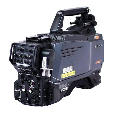
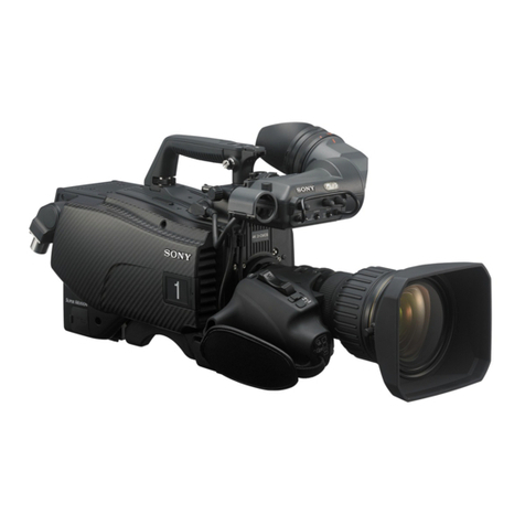
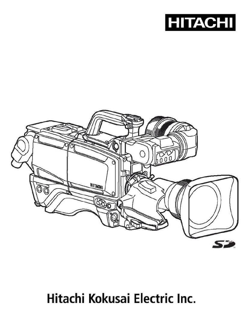
Sony HDC-900 Series User manual

HD COLOR CAMERA
HDC-900
HDC-950
HDC-900/L
MAINTENANCE MANUAL
1st Edition
Serial No. 10001 and Higher: HDC-900
Serial No. 10001 and Higher: HDC-950
Serial No. 30001 and Higher: HDC-900/L

HDC-900/950 MM
!WARNING
This manual is intended for qualified service personnel only.
To reduce the risk of electric shock, fire or injury, do not perform any servicing other than that
contained in the operating instructions unless you are qualified to do so. Refer all servicing to
qualified service personnel.
!WARNUNG
Die Anleitung ist nur für qualifiziertes Fachpersonal bestimmt.
Alle Wartungsarbeiten dürfen nur von qualifiziertem Fachpersonal ausgeführt werden. Um die
Gefahr eines elektrischen Schlages, Feuergefahr und Verletzungen zu vermeiden, sind bei
Wartungsarbeiten strikt die Angaben in der Anleitung zu befolgen.Andere als die angegeben
Wartungsarbeiten dürfen nur von Personen ausgeführt werden, die eine spezielle Befähigung
dazu besitzen.
!AVERTISSEMENT
Ce manual est destiné uniquement aux personnes compétentes en charge de l’entretien. Afin
de réduire les risques de décharge électrique, d’incendie ou de blessure n’effectuer que les
réparations indiquées dans le mode d’emploi à moins d’être qualifié pour en effectuer d’autres.
Pour toute réparation faire appel à une personne compétente uniquement.
Laser Diode Properties
Material : In GaAsp
Wave length : 1310 nm
Emission duration : Pulse code modulation
Laser output power : _8 dBm
CLASS 1
LASER PRODUCT
LASER KLASSE 1
PRODUKT
This HD color camera is classified as a CLASS 1
LASER PRODUCT.
The CLASS 1 LASER PRODUCT label is located on the
cabinet near the CCU connector.
CAUTION
Use of controls or adjustments or performance of
procedures other than those specified herein
may result in hazardous radiation exposure.

HDC-900/950 MM
For the customers in the Netherlands
Voor de klanten in Nederland
Dit apparaat bevat een MnO2-Li batterij voor memory
back-up.
Raadpleeg uw leverancier over de verwijdering van de
batterij op het moment dat u het apparaat bij einde
levensduur afdankt.
Gooi de batterij niet weg. maar lever hem in als KCA.
Bij dit produkt zijn batterijen geleverd.
Wanneer deze leeg zijn, moet u ze niet
weggooien maar inleveren als KCA.
1 (P)
CAUTION
Danger of explosion if battery is incorrectly replaced.
Replace only with the same or equivalent type
recommended by the manufacturer.
Dispose of used batteries according to the
manufacturer’s instructions.
Vorsicht!
Explosionsgefahr bei unsachgemäßem Austausch
der Batterie.
Ersatz nur durch denselben oder einen vom
Hersteller empfohlenen ähnlichen Typ. Entsorgung
gebrauchter Batterien nach Angaben des
Herstellers.
ATTENTION
Il y a danger d’explosion s’il y a remplacement
incorrect de la batterie.
Remplacer uniquement avec une batterie du même
type ou d’un type équivalent recommandépar le
constructeur.
Mettre au rebut les batteries usagées conformément
aux instructions du fabricant.
ADVARSEL!
Lithiumbatteri-Eksplosionsfare ved fejlagtig
håndtering.
Udskiftning måkun ske med batteri
af samme fabrikat og type.
Levér det brugte batteri tilbage til leverandøren.


1 (E)
HDC-900/950 MM
Table of Contents
Manual Structure
Purpose of this manual ........................................................................................ 5 (E)
Related manuals................................................................................................... 5 (E)
Contents ............................................................................................................... 6 (E)
1. Service Overview
1-1. Optional Fixtures...................................................................................1-1 (E)
1-2. Cleaning of Connector/Cable................................................................1-2 (E)
1-3. Circuit Description ................................................................................1-3 (E)
1-4. Notes on CCD Unit ...............................................................................1-6 (E)
1-4-1. Spare CCD Unit ...................................................................1-6 (E)
1-4-2. Description of CCD Block Number .....................................1-6 (E)
1-5. Notes on Flexible Card Wire.................................................................1-6 (E)
1-5-1. Disconnecting/Connecting Flexible Card Wire ...................1-6 (E)
1-5-2. Forming Before Installation (HDC-950)..............................1-7 (E)
1-6. Positioning Adjustment for Installing the Filter Knobs (HDC-950).....1-7 (E)
1-7. Notes on Replacement of Circuit Board ...............................................1-8 (E)
1-7-1. Note on Replacement of Parts..............................................1-8 (E)
1-7-2. Description on EEPROM (NV-RAM) Data ........................1-8 (E)
1-7-3. Adjustment after Replacement of Board..............................1-8 (E)
1-8. Disassembly of HDCZ Connector ........................................................1-9 (E)
1-9. How to Supply a Power of +12 V.........................................................1-9 (E)
1-10. Version-Up of ROM/AT-130 Board...................................................1-10 (E)
1-11. Note on Replacement of Lithium Battery ...........................................1-12 (E)
2. Replacement of Main Parts (HDC-900)
2-1. Replacing the CCD Unit .......................................................................2-1 (E)
2-2. Replacing the Filter Disk Unit ..............................................................2-2 (E)
2-2-1. Filter Disk Unit ....................................................................2-2 (E)
2-2-2. ND/CC Filters ......................................................................2-3 (E)
2-2-3. Driver Board.........................................................................2-4 (E)
2-3. Replacing the Power Assembly ............................................................2-4 (E)
2-4. Replacing the Fan..................................................................................2-5 (E)
2-5. Replacing the CCU Connector..............................................................2-6 (E)
2-6. Replacing the Boards ............................................................................2-7 (E)
2-6-1. SDI-49 Board .......................................................................2-7 (E)
2-6-2. RX-28 Board ........................................................................2-9 (E)
2-6-3. MB-883 Board ...................................................................2-11 (E)
2-6-4. CN-2073 Board ..................................................................2-13 (E)
http://getMANUAL.com

2 (E) HDC-900/950 MM
3. Replacement of Main Parts (HDC-950)
3-1. Replacing the CCD Unit .......................................................................3-1 (E)
3-2. Replacing the Filter Disk Unit ..............................................................3-2 (E)
3-2-1. Filter Disk Unit ....................................................................3-2 (E)
3-2-2. ND/CC Filters ......................................................................3-4 (E)
3-2-3. Driver Board.........................................................................3-5 (E)
3-3. Replacing the AC/DC Converter Unit ..................................................3-5 (E)
3-4. Replacing the Fan..................................................................................3-7 (E)
3-4-1. Rear Fan ...............................................................................3-7 (E)
3-4-2. Front Fan ..............................................................................3-8 (E)
3-5. Replacing the Side Switches (SW-1014 Board) ...................................3-9 (E)
3-6. Replacing the VF DISP Switches (SW-1016 Board)..........................3-10 (E)
3-7. Replacing the CCU Connector ............................................................3-11 (E)
3-8. Replacing the TRACKER Connector .................................................3-12 (E)
3-9. Replacing the PROMPTER Connector ...............................................3-13 (E)
3-10. Replacing the VF Connector ...............................................................3-14 (E)
3-11. Replacing the TEST OUT Connector .................................................3-14 (E)
3-12. Replacing the MIC Connector ............................................................3-15 (E)
3-12-1. FRONT MIC Connector ....................................................3-15 (E)
3-12-2. Replacing the AUDIO IN Connector .................................3-16 (E)
3-13. Replacing the INCOM Connector.......................................................3-17 (E)
3-14. Replacing the Boards ..........................................................................3-18 (E)
3-14-1. RX-28 Board ......................................................................3-18 (E)
3-14-2. SDI-49 Board .....................................................................3-19 (E)
3-14-3. CN-2018 Board ..................................................................3-20 (E)
3-14-4. CN-1964 Board ..................................................................3-21 (E)
3-14-5. MB-882 Board ...................................................................3-22 (E)
4. Replacement of CCD Unit Boards
4-1. CN-1961 Board .....................................................................................4-1 (E)
4-2. RP-114 Board ........................................................................................4-2 (E)
4-3. DR-412 Board .......................................................................................4-2 (E)
4-4. TG-214 Board .......................................................................................4-2 (E)
4-5. CN-1947 Board .....................................................................................4-3 (E)
4-6. DU-69 Board .........................................................................................4-3 (E)
4-7. PA-239 Board........................................................................................4-4 (E)
4-8. NR-69 Board .........................................................................................4-4 (E)

3 (E)
HDC-900/950 MM
5. SERVICE Menu
5-1. Setup Menu ...........................................................................................5-1 (E)
5-2. TOP Menu.............................................................................................5-4 (E)
5-3. SERVICE Menu....................................................................................5-5 (E)
5-4. Manual RPN Correction........................................................................5-7 (E)
5-5. Setting the RTC.....................................................................................5-8 (E)
6. Electrical Alignment
6-1. Preparations...........................................................................................6-2 (E)
6-1-1. Equipment Required.............................................................6-2 (E)
6-1-2. Precautions on Adjustments .................................................6-2 (E)
6-1-3. File data at Adjustment ........................................................6-2 (E)
6-1-4. Maintaining the Grayscale Chart .........................................6-3 (E)
6-1-5. Description on Setup Menu..................................................6-5 (E)
6-1-6. Connection of Equipment ....................................................6-6 (E)
6-1-7. Initial Settings ......................................................................6-6 (E)
6-2. Automatic Adjustment ..........................................................................6-7 (E)
6-3. PA-239 Board Adjustment....................................................................6-8 (E)
6-3-1. PA Balance Adjustment .......................................................6-8 (E)
6-3-2. PA Gain Adjustment ............................................................6-9 (E)
6-3-3. RPN Adjustment ................................................................6-10 (E)
6-4. VA-196 Board Adjustment .................................................................6-10 (E)
6-4-1. VA Gain Adjustment..........................................................6-10 (E)
6-5. Video System Level Adjustment (When using the Setup Menu) .......6-11 (E)
6-5-1. White Shading Adjustment ................................................6-11 (E)
6-5-2. H/V Ratio Adjustment........................................................6-13 (E)
6-5-3. Detail Level Adjustment ....................................................6-14 (E)
6-5-4. Crispening Adjustment.......................................................6-14 (E)
6-5-5. Level Dependent Adjustment.............................................6-15 (E)
6-5-6. Detail Clip Adjustment ......................................................6-15 (E)
6-5-7. Auto-iris Adjustment..........................................................6-16 (E)
6-5-8. Pedestal Level Adjustment.................................................6-17 (E)
6-5-9. Flare Adjustment ................................................................6-17 (E)
6-5-10. Gamma Correction Adjustment .........................................6-18 (E)
6-5-11. Knee Point/Knee Slope Adjustment...................................6-18 (E)
6-5-12. White Clip Level Adjustment ............................................6-19 (E)
6-5-13. File Store ............................................................................6-20 (E)
6-6. Video System Level Adjustment (When using MSU)........................6-20 (E)
6-6-1. White Shading Adjustment ................................................6-20 (E)
6-6-2. H/V Ratio Adjustment........................................................6-22 (E)
6-6-3. Detail Level Adjustment ....................................................6-22 (E)
6-6-4. Crispening Adjustment.......................................................6-23 (E)
6-6-5. Level Dependent Adjustment.............................................6-23 (E)
4 (E) HDC-900/950 MM
6-6-6. Detail Clip Adjustment ......................................................6-24 (E)
6-6-7. Auto-iris Adjustment ..........................................................6-25 (E)
6-6-8. Pedestal Level Adjustment .................................................6-25 (E)
6-6-9. Flare Adjustment ................................................................6-26 (E)
6-6-10. Gamma Correction Adjustment .........................................6-26 (E)
6-6-11. Knee Point/Knee Slope Adjustment...................................6-27 (E)
6-6-12. White Clip Level Adjustment ............................................6-28 (E)
6-6-13. File Store ............................................................................6-28 (E)
6-7. Adjustment After Replacement of ND Filter ......................................6-29 (E)
6-8. Filter Positioning Adjustment .............................................................6-30 (E)

5 (E)
HDC-900/950 MM
Manual Structure
Purpose of this manual This manual is the maintenance manual of HD Color Camera HDC-900/950.
This manual is intended for use by trained system and service engineers, and
describes the information regarding the circuit description, replacement of main
parts, SERVICE menu and electrical alignment.
Related manuals Besides this maintenance manual, the following manuals are available.
..
..
.HDC-900 Operation Manual (Supplied with HDC-900)
This manual is necessary for the use and the operation of the HDC-900.
Part number: 3-204-021-XX
..
..
.HDC-950 Operation Manual (Supplied with HDC-950)
This manual is necessary for the use and the operation of the HDC-950.
Part number: 3-204-027-XX
..
..
.Installation and Maintenance Manual (Supplied with HDC-900/950)
This manual intended for use by trained system and service engineers describes
the information regarding the installation of the HDC-900/950 and the information
required for initial services.
Part number: 3-204-338-XX
..
..
.“Camera System HDC-900 Series Maintenance Manual” CD-ROM
(Available on request)
This “Camera System HDC-900 Series Maintenance Manual” CD-ROM allows
you to search for the detailed information (parts list, semiconductor pin assign-
ments, block diagrams, schematic diagrams and board layouts) of the HD color
camera HDC-900/950, that of HD camera control unit HDCU-900 and that of
option board HKCU-901/902/903/904 for HDCU-900 that premises the service on
the component level.
In addition to the above-described information, you can view the PDF files of the
related manuals of the equipment models that are used in the HDC-900 series
camera system. (Contents are subject to change without notice.) For obtaining,
contact your local Sony Sales Office/Service Center.
..
..
.System Manual (Available on request)
This manual is necessary for connection and operation of this unit and other
peripheral equipment.
If this manual is required, please contact your local Sony Sales Office/Service
Center.

6 (E) HDC-900/950 MM
..
..
.“Semiconductor Pin Assignments”CD-ROM (Available on request)
This “Semiconductor Pin Assignments”CD-ROM allows you to search for
semiconductors used in Communication System Solutions Network Company
equipment.
Semiconductors that cannot be searched for on this CD-ROM are listed in the
maintenance manual for the corresponding unit. The maintenance manual contains
a complete list of all semiconductors and their ID Nos., and thus should be used
together with the CD-ROM.
Part number: 9-968-546-XX
Contents The following are summaries of all the sections for understanding the contents of
this manual.
Section 1 Service Overview
Describes circuit description and notes on services.
Section 2 Replacement of Main Parts (HDC-900)
Describes about the replacement of the CCD unit, filter disk unit, power assembly,
fan, CCU connector and circuit boards.
Section 3 Replacement of Main Parts (HDC-950)
Describes about the replacement of the CCD unit, filter disk unit, AC/DC converter,
fans, switches, connectors and circuit boards.
Section 4 Replacement of CCD Unit Boards
Describes about the replacement of CCD unit boards.
Section 5 SERVICE Menu
Describes the SERVICE menu in the setup menu displayed on the viewfinder.
Section 6 Electrical Alignment
Describes electrical adjustment necessary for maintenance of the unit or replacement
of parts.

1-1 (E)
HDC-900/950 MM
Section 1
Service Overview
1-1. Optional Fixtures
Name Sony Part No. Remarks
EX-738 Board A-8327-351-A For extension of plug-in boards
Alignment sleeve remover HC-001 J-6480-010-A For female connector
Cotton swab —— Diameter about 4 mm
Any available on the market

1-2 (E) HDC-900/950 MM
Optical contacts (white)
Insert the shorter nose end
Shock absorber portion Handle
1-2. Cleaning of Connector/Cable
The photo receptive condition of the optical connector can
be checked at the SDI page of the DIAGNOSIS menu of
this unit. (For details, refer to Section 3-7 of the Installa-
tion and Maintenance Manual.) It can also be checked at
OPTICAL CONDITION of the DPR board of the camera
control unit.
When lit in green: Normal (_17 dBm or above)
When lit in yellow: Normal (_17 to _20 dBm)
When lit in red: Abnormal (Less than _20 dBm)
When lit in red, be sure to clean the optical contact por-
tions.
When lit in yellow, cleaning is recommended.
The attenuation of the photo-receptive level may cause
transmission error between the camera and HDCU. In the
case of attenuation, be sure to clean optical contact por-
tions proceeding as follows. The optical contact portions
exist in the optical connector on the camera or HDCU, and
in the optical/electrical cables, and connection connectors
which are connected to the SDI or RX board.
Tools Required
.Alignment sleeve remover HC-001
(for female connector)
Sony P/N: J-6480-010-A
n
Insert the shorter nose end when removing/installing the
alignment sleeve.
Grasp not the shock absorber portion of the remover but
the handle in use.
.Cotton swabs (commercially available)
Cleaning
Male connector
Clean the tip of the white optical contacts by a cotton swab
moistened with alcohol.
Female connector
The optical contacts for female connector are in an unex-
posed state. In cleaning, it is necessary to be exposed by
removing the alignment sleeve in advance. Proceed as
follows.
1. Insert the alignment sleeve remover into the alignment
sleeve in the straight line and turn it clockwise.
1-2. Cleaning of Connector/Cable

1-3 (E)
HDC-900/950 MM
Optical contact (white)
Optical contacts (white)
Alignment sleeve
2. When the turn stops, pull out the remover in the
straight line forcedly.
n
The alignment sleeve can be removed/reinstalled with
the sleeve itself attached to the tip of the remover.
Great care should be taken so as not to lose or damage
the alignment sleeve.
(Alignment sleeve: Sony P/N 9-980-074-01)
3. Clean the tip of the white optical contacts by a cotton
swab moistened with alcohol.
4. Insert the remover with the alignment sleeve attached
to its tip, and push it until it clicks.
5. Rotate the remover counterclockwise to install the
alignment sleeve, and extract the remover.
Connection connector
After replacing the optical connector of the camera or
HDCU, or replacing the SDI-44/RX-28 board, clean the tip
of the white optical contact of the connection connector by
a cotton swab moistened with alcohol.
1-2. Cleaning of Connector/Cable
1-3. Circuit Description
BI-145 board
The BI-145 board supplies the DC bias required for the
CCD. The CCD output is sent through a buffer to the NR-
69 board. The BI-145 board mounts horizontal clock
drivers for the CCD and a reset gate driver.
CN-1947 board
CN-1947 board is the relay board that supplies each CCD
driving pulse generated on the DR-412 board to the BI-145
board. The CN-1947 board also generates the voltage used
for the horizontal clock drivers for the CCD.
DR-412 board
The DR-412 board mounts the vertical clock drivers for
CCD driving, drivers for a shutter pulse and V/H driver.
And the DR-412 board generates the V-sub voltage proper
to the CCD and then supplies it to the CCD.
The voltage produced using a DC/DC converter is sent
through this board to each board.
TG-214 Board
The TG-214 board synchronizes with the CHB-F and
CHB-H signals sent from the SG-268 board to create the
CCD drive pulses and sample-hold pulses. It also PLL
locks the INT-H signal generated in the board with the
CHB-H signal for synchronization.
DPR-154/156 Board
The R, G, and B signals input from the VA-196 board are
A/D converted after passing through the pre-filter.
They are sent the DPR-156 board and returned to the DPR-
154 board again. They are next subject to camera process-
ing such as knee and gamma processing by the DSP IC and
enhancer processing.
The signal output from DSP IC is interfaced with the
DAD-37 board in the digital signal form. It is then D/A
converted and output to the VDA-55 board.
PA-239 board
The CCD output is split into two channels. The PA-239
board is provided with a multiplexer which is used to
return the split signals to thier original state.
NR-69 board
The NR-69 board performs correlative double sampling so
as to extract a reset noise from the CCD output.

1-4 (E) HDC-900/950 MM
1-3. Circuit Description
DU-69/RP-114 boards
The DU-69 and RP-114 boards mount the RPN correction
circuit for the CCD.
VA-196 board
The VA-196 board consists of the video amplifier, gain-up
amplifier, white balancing amplifier, white/black shading
correction circuits, test signal generator, diagnosis circuit
and so on.
The R, G and B video signals input from the CCD block
are passed through the differential amplifier and pre-white-
clip correction circuit. And then the residual component of
clocks is removed at the LPF. The differential amplifier
clamps the black level and also mixes the black shading
correction signal with the video signals.
They are then input to the flair circuit after passing through
the preset gain adjustment control, black set circuit, gain
up amplifier, and white balance amplifier. They are then
PRE KNEE processed in the amplifier in the next stage
and output to the DPR board. The white balancing amplifi-
er performs the white shading correction too.
In addition, the VA-196 board has the test signal generator
which can generate two types of test signals. The test
signals can be used for various adjustments or maintenance
by switching the output signal from the CCD signal to
either of test signals. The adjustment data for the VA-196
board is stored in the EEPROM on the board.
AT-130 board
AT-130 board consists of a microcomputer for system
control and its peripheral circuits. The main program is
written in the EPROM on the board. And the camera
control data is kept in the NVRAM.
Moreover, the AT-130 board is provided with the interface
circuit with the lens and auto-iris control circuit.
VDA-55 Board
The R, G, and B signals and Y, PB, and PRsignals input
from the DPR-154 board, and RET (Y/PB/PR) signals input
from the DAD-37 board are selected by the switch, passed
through the cable compensation circuit (25 m or 50 m),
added with SYNC, and output from the 75 Zdriver to the
VCR connector.
After the signal selected from the R, G, B, and Y signals or
RET signal (Y) of the camera is mixed with two types of
zebra signals, character signal, cursor signals, and VF
detail signals, it is passed through the aspect modulation
circuit, added with SYNC, and output to the viewfinder
and TEST OUT connector from the 75 Zdriver. When
only the camera is used, the camera and VCR playback
signal are switched by the VCR PB ON signal, and output
from this 75 Zdriver. Other VDA-55 boards are also
provided with a self-diagnosis circuit.
DAD-37 board
The DAD-37 board performs digital-to-analog conversions
and transmitting/receiving of the parallel digital signal for
communication in digital form. Parallel-to-serial conver-
sion is performed by the SDI-49 board.
Transmitting system:
.The Y/PB/PRsignals input from DPR-154 board are
formatted for communication in digital and are then sent
to the SDI-49 board.
.The intercom audio and microphone audio signals are
multiplexed by format IC.
.The camera command signal is multiplexed by format
IC.
.The format ID is multiplexed by format IC.
Receiving system:
.Separates the following signals from the parallel-to-
digital signal sent from the SDI-49 board.
Y/PB/PRvideo signals (CCU RET)
Intercom audio and program audio signals
Prompter signal
CCU command
Synchronizing signal
.The Y signal is digital-to-analog converted at 74-MHz
rate and the PBand PRsignals are digital-to-analog
converted at 37-MHz rate.
.Send the prompter signal from the HD CCU to the DAP
board.

1-5 (E)
HDC-900/950 MM
1-3. Circuit Description
SDI-49 board
The SDI-49 board converts the parallel Y/PB/PRsignal
multiplexed by the DAD-37 board to a serial digital signal
and outputs it from the SERIAL OUT connector. And
SDI-49 board also converts the serial digital signal to an
optical signal and outputs it to the HD CCU.
The serial digital signal input from the RX-28 board is
separated from clocks and is converted to a parallel digital
signal. The converted signal is then output to the DAD-37
board.
RX-28 board
The optical signal transmitted from the HD CCU is
converted to an electric signal by the RX-28 board and is
output to the SDI-49 board. And the photo-reception level
is detected by the RX-28 board and the detection value is
output to the SDI-49 board.
AU-271 board, DU-104 board
The AU-271 board consists of the following circuits:
.Two intercom input amplifiers
.Two microphone input amplifiers
.Power supply for the above input amplifiers
.Two intercom receiving output amplifiers
.Two PGM output circuits
.TRACKER input/output circuit
.VTR intercom circuit
.Earphone output circuit
The input signal at the INCOM connector is converted to
_20 dBu in level and is output to the DAP-24 board, after
the microphone selection (carbon or dynamic microphone)
is made and the microphone level +6 dB, 0 dB or _6 dB is
selected.
The input signal at the MIC connector is also converted to
_20 dBu in level and is output to the DAP-24 board, after
the microphone level _20 dB, _30 dB, _40 dB, _50 dB,
or _60 dB is selected. The same signal is output to the
VTR connector in parallel. The microphone connected to
the MIC connector is selectable from the microphone
without power, AB powering or phantom microphone.
The intercom receiving signal is adjusted in level by EVR,
with which the PGM and TRACKER signals are mixed,
and is then output through the buffer. By setting the
internal switch of DU-104 board, the intercom receiving
signal can be interfaced with the optional RTS kit.
The PGM signal is adjusted in level by EVR, with which
the intercom signal is mixed, and is then output through the
output amplifier.
DAP-24 board
The intercom signals and microphone signals in two
channels each, which are sent from the AU-271 board, are
analog-to-digital converted by the DAP-24 board and are
output via the DAD-37 board to the HD CCU.
The digital audio signals sent from the DAD-37 board is
converted to analog intercom signals and analog program
signals in two channels each and are output to the AU-271
board.
The DAP-24 board is equipped with the PLL circuit to
synchronize the video signal with clocks as reference
during analog-to-digital or digital-to-analog conversion.
In addition, the DAP-24 board has the detection circuit to
detect the connection status with the HD CCU, standby
intercom circuit, interface circuit with the viewfinder and
diagnosis circuit.
The prompter signal from the DAD-37 board is output
from the PROMPTER OUT after being decoded and
digital-to-analog converted.
SG-268 board
The SG-268 board consists of the pulse generators.
.Generates various pulses as the reference of the VCO
(74.25 MHz or 74.175 MHz) on the circuit boards. This
pulse generator synchronizes the HD CCU or external
sync signal input.
.Generates various marker signals.
.Outputs the status signal or diagnosis data as a character
data from the character generator.
.Stores the oscillation frequency, its adjustment data in
the EEPROM on the SG-268 board.
http://getMANUAL.com

1-6 (E) HDC-900/950 MM
1-4. Notes on CCD Unit
1-4-1. Spare CCD Unit
If replacing CCD unit, please order the CCD UNIT HKC-
C900R through the sales channel.
1-4-2. Description of CCD Block Number
Every CCD unit has its own ID number called CCD block
number. It shows the CCD block type and serial number
for the CCD block.
The CCD block number label is put in the CCD unit.
1-4. Notes on CCD Unit
1-5. Notes on Flexible Card Wire
1-5-1. Disconnecting/Connecting Flexible
Card Wire
The flexible card wires are used between the boards of
HDC-900 and HDC-950. Take care not to bend forcedly
these flexible card wires. This shortens the wire life.
HDC-900
Between CN-1974 and AT-131
Between CN-1961 and DR-412
Between CN-1961 and PA-239
HDC-950
Between CN-1961 and DR-412
Between CN-1961 and PA-239
Between MB-882 and CN-2018
Between MB-882 and CN-1951
Between MB-882 and SW-1017
Disconnectiong
1. Trn off the power.
2. Slide portions A in the direction of the arrow to unlock
and pull out the flexible card wire.
Connecting
m
.Be careful not to insert the flexible card wire obliquely.
.Check that the conducive surface of the flexible card
wire is not soiled with dust.
1. Slide portions A in the direction of the arraw and insert
the flexible card wire as far as it will go with the
conductive serface down.
2. Slide portions A in the reverse direction to lock.
Example : AJ xxxxx Serial number for the CCD unit
CCD block type
A
Conductive
surface
A

1-7 (E)
HDC-900/950 MM
1-5-2. Forming Before Installation (HDC-950)
If using a new flexible card wire, be sure to hand-form it as
shown in the figure before installation.
n
Never fold it back after being formed once.
.MB-882 board CN24 ↔CN-2018 board CN2
.MB-882 board CN29 ↔CN-1951 board CN6
1-6. Positioning Adjustment for
Installing the Filter Knobs
(HDC-950)
Installing the filter knobs, be sure to perform the following
adjustment.
1. Remove the inside panel. (Refer to Section 1-4 of
Installation and Maintenance Manual.)
2. Align the CC filter knob number with the number
(CC) on the filter disk unit and tighten the two set-
screws.
Tightening torque : 20 x10_2N.m (2.0 kgf.cm)
3. Rotate the CC filter knob and check that it moves
smoothly.
4. Align the ND filter knob number with the number
(ND) on the filter disk unit and tighten the two set-
screws.
Tightening torque : 20 x10_2N.m (2.0 kgf.cm)
5. Rotate the ND filter knob and check that it moves
smoothly.
1-5. Notes on Flexible Card Wire
1-6. Positioning Adjustment for Installing the Filter Knobs (HDC-950)
43
25
56
Conducting surface (silver)
Insulating surface (blue)
unit : mm
CN-2018(CN2) MB-882(CN24)
30
Conducting surface
(silver)
Insulating surface (blue)
unit : mm
170
CN-1951(CN6)
MB-882(CN29)
1B
1
B
ND
1 CLEAR
2 1/4 ND
3 1/8 ND
4 1/16ND
5 1/64ND
CC
A
CROSS
B
CLEAR
C
4300K
D
6300K
E
8000K
Filter disk unit
Setscrews
(WP2 x3)
Setscrews
(WP2 x3)

1-8 (E) HDC-900/950 MM
1-7. Notes on Replacement of Circuit
Board
1-7-1. Note on Replacement of Parts
Every electrical part mounted on the mounted circuit
boards used in the CCD unit cannot be replaced.
And every electrical part mounted on the SDI-49 and RX-
28 boards cannot be replaced too. If there is any defective
part, replace the mounted circuit board itself. Refer to
Sections 2-6-1 and 2-6-2 (HDC-900) or 3-14-1 and 3-14-2
(HDC-950) for details on replacement.
1-7-2. Description on EEPROM (NV-RAM)
Data
The table below gives the stored data of EEPROM (NV-
RAM) on every printed circuit board.
Board Ref. No. Stored data
AT-130 IC5*Paint data, Fails
DAD-37 IC6 DAD-37 adjustment data
DPR-154 IC212 DPR-154 adjustment data
RP-114 IC22 RP-114 adjustment data
SG-268 IC101 SG-268 adjustment data
VA-196 IC200 VA-196 adjustment data
VDA-55 IC8 VDA-55 adjustment data
*: NV-RAM
n
The IC listed above cannot be replaced because it is the
EEPROM (NV-RAM) that is storing data inherent in the
board. The part number listed in “Spare Parts” is for
EEPROM (NV-RAM) which is not programmed. If
replacement is needed, consult your Sony representatives.
1-7-3. Adjustment after Replacement of
Board
When replacing some electrical parts on the circuit board,
or the circuit board itself, be sure to perform the following
adjustments after replacement. If no adjustment item is
listed, no adjustment is required.
Board/Block For Part For Board
Replacement Replacement
AT-130 —— ——
AU-271 —— ——
DAD-37 —— ——
DAP-24 —— ——
DPR-154 VTR26P OUT VTR26P OUT
Level Adjustment Level Adjustment
DPR-156 —— ——
DU-104 —— ——
PA-239 PA-239 Board PA-239 Board
Adjustment Adjustment
RE-181/182/184 —— ——
RX-28 —— ——
SDI-49 —— ——
SG-268 —— ——
VA-196 VA-196 Board VA-196 Board
Adjustment Adjustment
VDA-55 VTR26P OUT VTR26P OUT
Level Adjustment Level Adjustment
Filter Disk Unit —— Filter Drive
Adjustment
1-7. Notes on Replacement of Circuit Board

1-9 (E)
HDC-900/950 MM
1-8. Disassembly of HDCZ Connector
1. Remove the two screws and three setscrews.
2. Connect the plug to the VTR or camera.
3. Loosen the plug counterclockwise by pliers.
4. Disassemble as illustrated and unsolder.
1-8. Disassembly of HDCZ Connector
1-9. How to Supply a Power of +12 V
1-9. How to Supply a Power of ++
++
+12 V
Each the model HDC-900 and HDC-950 can supply 12V
for MIC POWER to the microphone connected the AU-
DIO IN connector.
When require this power output:
First replace the resisters as shown in the side A and B of
the AU-271 board as follows.
Refer to the Operation Manual and set on the MIC POW-
ER switch of AUDIO IN connector.
AU-271 board
R526, R529, R538, R541
Old part No. New part No.
1-216-797-11 (10 Z) 1-216-837-11 (22 kZ)
R526
R538
43 2 15
A
B
C
D
E
F
G
AU-271 Board (A side)
43215
A
B
C
D
E
F
G
R529
R541
AU-271 Board (B side)

1-10 (E) HDC-900/950 MM
1-10. Version-Up of ROM/AT-130 Board
The ROM (IC1 on the AT-130 board) version can be upgraded using the memory stick. Follow the
procedure shown below.
m
.Prepare the memory stick in which the upgraded program has been written.
.Refer to section 5-1 for basic operations of the setting menu.
.The version number of the ROM can be confirmed on the BOARD STATUS page of the DIAGNOSIS
menu.
1. Turn the power of the unit on. Open the VF DISPLAY page of the OPERATION menu and move the
cursor to the page number.
VF DISPLAY page
2. HDC-900 :
Press the MENU SELECT switch toward the “ENTER”side to change the cursor to “?”.
HDC-950 :
Press the rotary encoder to change the cursor to “?”.
3. HDC-900 :
Press the MENU SELECT switch toward the “ENTER”side again. Insert the memory stick into the
camera unit with pressing the MENU SELECT switch toward the “ENTER”side, and remain
presseng the MENU SELECT switch toward the “ENTER”side so that “MEMORY STICK AC-
CESS”is displayed on the screen.
HDC-950 :
Press the rotary encoder again. Insert the memory stick into the camera unit with pressing the rotary
encoder and remain pressing the rotary encoder so that “MEMORY STICK ACCESS”is displayed
on the screen.
n
While “MEMORY STICK ACCESS”is displayed, do not eject the memory stick.
<VF DISPLAY>
EX : ON BATT : OFF
ZOOM : OFF RETURN: ON
FOCUS : OFF
ND : ON
CC : ON
IRIS : ON MESSAG: ALL
WHITE : OFF
D5600K: ON
GAIN : ON
SHUTT : ON
Page number
1
1-10. Version-Up of ROM/AT-130 Board
Other manuals for HDC-900 Series
3
This manual suits for next models
2
Table of contents
Other Sony CCTV Camera manuals

Sony
Sony HDC5500 User manual

Sony
Sony KDP-673SH20 User manual

Sony
Sony FCB-EX2400 User manual

Sony
Sony Super HAD CCD SSC-DC314 User manual

Sony
Sony HDC5500 User manual

Sony
Sony FCBEH6300 User manual

Sony
Sony FCB-EV7520 User manual

Sony
Sony super motion hdc4300 User manual

Sony
Sony FCB-EV7320 User manual

Sony
Sony FCB-CX12E User manual