7
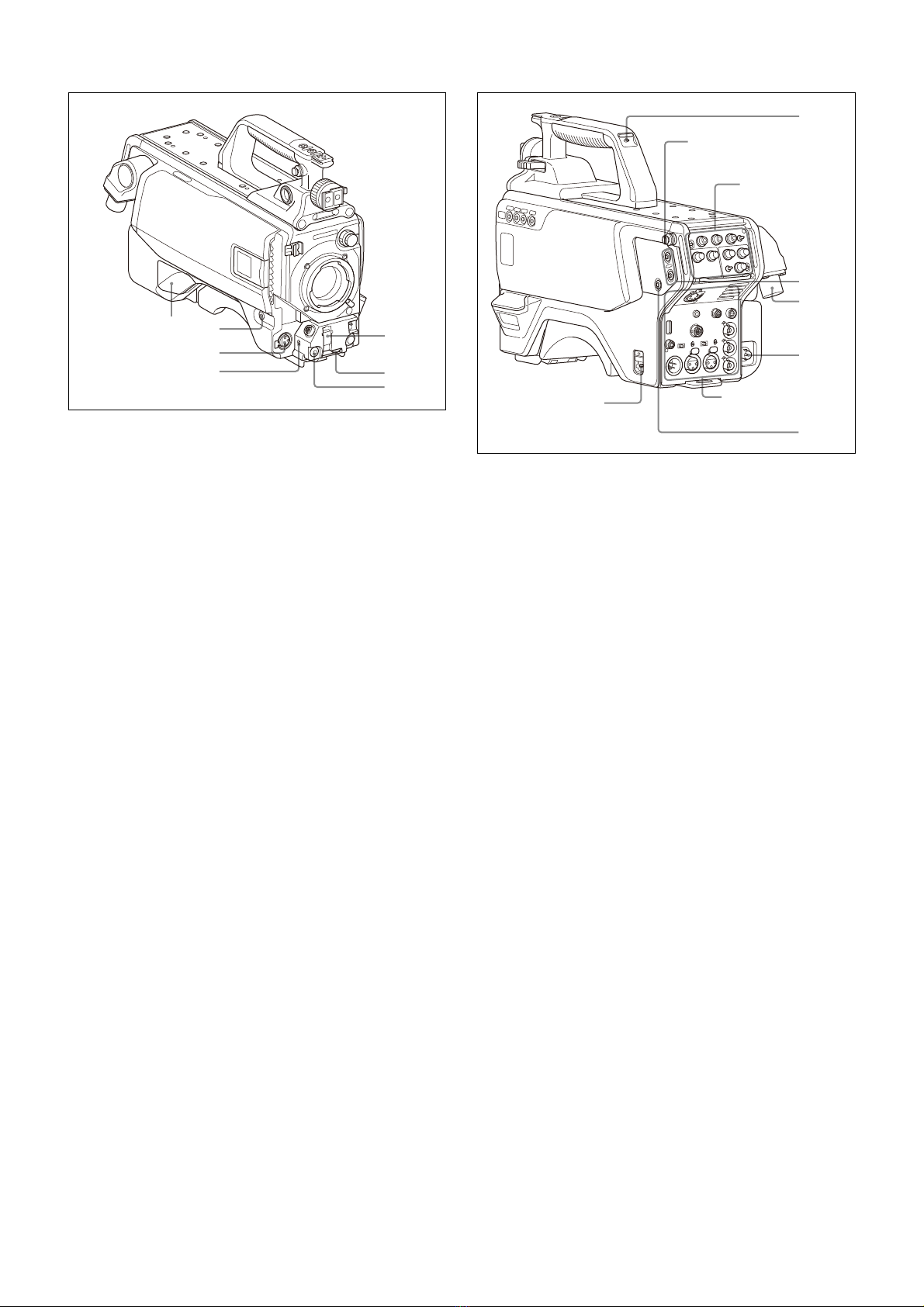
Controls and Connectors
Front right
aINCOM1 (intercom 1) button
The intercom 1 microphone is turned ON while this button is
held pressed.
You can also assign other functions to this button, using the
menu displayed on the viewfinder screen.
bRET 1 (return video 1) button
The return video 1 signal from the camera control unit is
monitored on the viewfinder screen while this button is
pressed. It function the same as the RET 1 button on the side
(page 8) and RET/ASSIGNABLE button A on the operation
panel on the rear of the camera (page 9).
You can also assign other functions to this button, using the
menu displayed on the viewfinder screen.
cASSIGN (assignable) A, B, C, D switches
You can assign a function using the menu displayed on the
viewfinder screen.
You can also display the assigned function name by attaching
the corresponding label (supplied) for the assigned function.
dFilter select control
Turn the knob to select the internal filter setting.
eAUTO W/B BAL (white and black balance automatic
adjustment) switch
To automatically adjust white and black balance when the
camera is used in standalone status without connecting to the
camera control unit.
WHT: Automatically adjust white balance.
BLK: Automatically adjust black balance.
fGAIN switch
To select the gain of the video amplifier based on lighting
conditions when the camera is used in standalone status
without connecting a camera control unit.
When shipped from the factory, the values set are L = 0 dB,
M = 6 dB, and H = 12 dB.
gOUTPUT (output signal selection)/AUTO KNEE switch
To select the signal (color bar signal or camera’s video signal)
to be used as output to the viewfinder or a video monitor when
the camera is used in standalone status without connecting a
camera control unit.
When the camera’s video signal is being used as output, the
auto knee function may be used.
The relationship between the switch setting and the output
signal and auto knee function is shown in the table below.
hWHITE BAL (white balance memory selection) switch
To select the white balance adjustment method or the memory
used to store the adjusted value when the camera is used in
standalone status without connecting a camera control unit.
PRST (preset): White balance is adjusted to a preset value
corresponding to a color temperature of 3200K.
A or B: Selects memory A or B.
iDISPLAY switch
The functions of the DISPLAY switch are as follows:
DISPLAY: Characters and messages showing the camera
settings and operating status may be displayed on the
viewfinder screen.
OFF: Status messages will not appear on the viewfinder
screen.
MENU: Menus for camera settings will be displayed on the
viewfinder screen.
jSTATUS/CANCEL switch
STATUS: When no menu is displayed on the viewfinder
screen, the status information of this camera is displayed.
CANCEL: When a menu is displayed on the viewfinder
screen, you can cancel any changed settings or return
the display to the previous menu.
kMENU SEL (menu select) knob/ENTER button (rotary
encoder)
To select settings from menus displayed on the viewfinder
screen (by rotating the knob) and to confirm settings (by
pushing the button).
You can change the ECS frequency by pushing the ENTER
button when no menu is displayed on the viewfinder screen.
Make sure that the camera is used in standalone status
without connecting a camera control unit, and the shutter
mode is set to ECS. When the camera is used in standalone
status and the shutter mode is set to other than ECS, the VF
DETAIL function can be adjusted.
Note
When a camera control unit or a remote control device, such
as an MSU or RCP-series Remote Control Panel, is
connected, the functions of 5to 8are controlled from the
external control device and the controls on the camera are
disabled.
OUTPUT AUTO KNEE Function
BARS OFF Output is a color bar signal.
CAM OFF Output is the camera’s video signal.
The auto knee circuit is disabled.
CAM ON Output is the camera’s video signal.
The auto knee circuit is enabled.