manuals.online logo
Brands
  1. Home
  2. •
  3. Brands
  4. •
  5. Sony
  6. •
  7. CD Player
  8. •
  9. Sony CDP-C90ES User manual

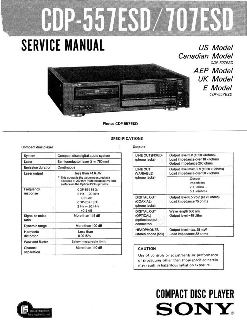
Sony CDP-C90ES User manual

CDP-CS0ES/C910
SERVICE
MANUAL
US
Model
Canadian
Model
CDP-C90ES
US
Model
Canadian
Model
AEP
Model
E
Model
Australian
Model
CDP-C910
Photo
:
CDP-C9O0ES
Mode!
Name
Using
Similar
Mechanism
|
New
Mechanism
CD
Mechanism
Name
CDM10-5BD7
|
Base
Unit
Name
BU-5BD7
SPECIFICATIONS
Compact
Disc
Player
Dimensions
(w/h/d)
Frequency
response
2
Hz-
20
kHz
(+0.3
dB)
CDP-C910
mode!
:Approx.
430
X
125
&
385mm
Signal
to
noise
ratio
More
than
110
dB
(17
X
5
X
15'/«
inches)
Dynamic
range
More
than
100
dB
CDP-C90ES
model
:Approx.
470
X
125
X385mm
Harmonic
distortion
Less
than
0.0030%
(188/gx
5
X
15'/4
inches)
Channel
separation
More
than
105
dB
Including
projecting
parts
and
controis
Weight
Outputs
CDP-C910
modei
:A
Approx.
6.3kg(13lbs
150z),net
FI
I
$
eee
fed
eecanics
ae
kiloohms)
CDP-C90ES
mode!
:
Approx.
7.4kg(16Ibs
6
0z)net
10
kiloohms
Suppli
.
LINE
OUT
(VARIABLE)
Output
level
max
2
V
Euan
(phono
jacks)
(at
50
kiloohms)
onnecting
cord
Load
impedance
over
(2
phono
plugs
++
2
phono
plugs)
(1)
10
kiloohms
Disc
magazine
(1)
DIGITAL
OUTPUT
—-
Wave
length
660
nm
on
ee
(OPTICAL)
(optical
Output
level
—
18
dBm
iz
A
pattenes
(2)
Qutput
connector)
2
HEADPHONES
Output
level
max.
15
mW
Design
and
specifications
subject
to
change
without
(stereo
phone
jack)
Load
impedance
32
ohms
nonee:
General
Power
requirements
US,Canadian
model
:ACi20V,
60Hz
AEP
model
:220-230V
AC
,
50/60Hz
E
model
:110-120V
or
220-240V
AC
adjustable
50/60Hz
Australian
model
:AC240V,
50Hz/60Hz
Power
consumption
CDP-C910(US,
Australian)
model,
CDP-C90ES(US,
Canadian)
model
:18W
CDP-C910(Canadian,
AEP,
E,
Australian)
model
:15W
COMPACT
DISK
PLAYER
CDP-C90ES/C910
SAFETY
CHECK-OUT
After
correcting
the
original
service
problem,
perform
the
following
safety
check
before
releasing
the
set
to
the
customer:
Check
the
antenna
terminals,
metal
trim,
‘“‘metallized”’
knobs,
screws,
and
all
other
exposed
metal
parts
for
AC
leakage.
Check
leakage
as
described
below.
LEAKAGE
TEST
The
AC
leakage
from
any
exposed
metal
part
to
earth
ground
and
from
all
exposed
metal
parts
to
any
exposed
metal
part
having
a
return
to
chassis,
must
not
exceed
0.5
mA
(500
microampers).
Leakage
current
can
be
measured
by
any
one
of
three
methods.
1.
A
commercial
leakage
tester,
such
as
the
Simpson
229
or
RCA
WT-540A.
Follow
the
manufacturers’
instructions
to
use
these
instru-
ments.
2.
A
battery-operated
AC
milliammeter.
The
Data
Precision
245
digital
multimeter
is
suitable
for
this
job.
3.
Measuring
the
voltage
drop
across
a
resistor
by
means
of
a
VOM
or
battery-operated
AC
volt-
meter,
The
“limit”?
indication
is
0.75
V,
so
analog
meters
must
have
an
accurate
low-
voltage
scale.
The
Simpson
250
and
Sanwa
SH-63Trd
are
examples
of
a
passive
VOM
that
is
suitable.
Nearly
all
battery
operated
digital
multimeters
that
have
a
2
V
AC
range
are
suitable.
(See
Fig.
A)
To
Exposed
Metal
Parts
on
Set
|
AC
0.18uF
1.5k2
voltmeter
;
(0.75
V)
+
Earth
Ground
Fig.
A.
Using
an
AC
voltmeter
to
check
AC
leakage.
SAFETY-RELATED
COMPONENT
WARNING!!
COMPONENTS
IDENTIFIED
BY
MARK
A
OR
DOTTED
LINE
WITH
MARK
A
ON
THE
SCHEMATIC
DIAGRAMS
AND
IN
THE
PARTS
LIST
ARE
CRITICAL
TO
SAFE
OPERATION.
REPLACE
THESE
COMPONENTS
WITH
SONY
PARTS
WHOSE
PART
NUMBERS
APPEAR
AS
SHOWN
IN
THIS
MANUAL
OR
IN
SUPPLEMENTS
PUB-
LISHED
BY
SONY.
TABLE
OF
CONTENTS
Section
Title
Page
SECTION
1.
GENERAL:
*
-
ss
et
et
eet
eee
SECTION
2.
SWITCH
AND
SENSOR
OPERATIONS:
-
=
-
SECTION
3.
MECHANICAL
ADJUSTMENTS
-----
=
>
SECTION
4.
ELECTRICAL
BLOCK
CHECKING:
--
=~
=
SECTION
5.
DIAGRAMS
5-1.
Printed
Wiring
Boards:
=
+
+++
+
+>
5-2.
Schematic
Diagram
—
MAIN
Section
5-3.
Schematic
Diagram
—
BD
Section
—
°
-
18
5-4.
WAVEFORMS:
-
-
+
+
2
se
ee
ee
ee
SECTION
6.
EXPLODED
VIEWS
6-1.
Front
Pane!
Assembly
Section
-«*
+
=>
6-2.
Chassis
Assembly
Section
-*-*
+:
"+.
6-3.
MD
Section-]
*-
+
sete
ee
ee
tes
6-4.
MD
Section-2
-
+
+
++
eee
ee
eee
6-5.
Optical
Pick-Up
Block
Section:
*
-
=
=
SECTION
7.
ELECTRICAL
PARTS
LIST:
-
+++
+=:
-
MODEL
IDENTIFICATION
(Specification
Label)
CDP-C910
CDP-C90ES
SONY:
COMPACT
DISK
PLAYER
MMMM
bbb
MODEL
NO.
KY
US,
Canadian
model:
AC:
I|20V
60Hz
15W
AEP
model:
AC:
220-230V~50/60Hz
E
model:
AC:
110-120V,
220-230V~50/60Hz
15W
Australian
model:
AC:
240V~50/60Hz
ATTENTION
AU
COMPOSANT
AYANT
RAPPORT
A
LA
SECURITE!
LES
COMPOSANTS
IDENTIFIES
PAR
UNE
MARQUE
#\
SUR
LES
DIAGRAMMES
SCHEMATIQUES
ET
LA
LISTE
DES
PIECES
SONT
CRITIQUES
POUR
LA
SECURITE
DE
FONCTIONNEMENT.
NE
REMPLACER
CES
COM-
POSANTS
QUE
PAR
DES
PIECES
SONY
DONT
LES
NUMEROS
SONT
DONNES
DANS
CE
MANUEL
0U
DANS
LES
SUPPLEMENTS
PUBLIES
PAR
SONY.
*13
pectin,
This
section
is
extracted
from
instruction
manual.
|
MeYor-1ilela
Mey
Mmerelalige)
is
SECTION
1
GENERAL
CDP-C90ES/C910
Front
Panel
[21
}{20]
Refer
to
the
pages
indicated
in
@
for
details.
POWER
switch
©
Magazine
slot
@
TIME/MEMO
button
@
[4
|REPEAT
button
®
CHECK
(program
check)
button
®
CLEAR
(program
clear)
button
®
Display
window
@
FILE
button
@
ERASE
button
@
MUSIC
SCAN
button
@
EDIT/TIME
FADE
button
@
@
Track
buttons
@
DISC
selectors
@
DISC
SKIP
button
@
>10
(over
10)
button
@
el+lele
|e]
(als/s)s/2|s/ele
(No)
Remote
Commander
.
[16
PHONE
LEVEL/LINE
OUT
LEVEL
control
@
@
[17
PLAY
MODE
buttons
CONTINUE
button
©
SHUFFLE
button
®
PROGRAM
button
®
BANK
button
@
[18
HEADPHONES
jack
[19
LEVEL
FILE
button
@
20:
P(peak).SEARCH
button
®
(21:
FADER
button
®
(22.
<4
BP
(manual
search)
buttons
@
[23.4
PI
(AMS*)
buttons
@
[24M
(stop)
button
@
[25
Ml
(pause)
button/indicator
@
[26:B
(play)
button/indicator
@
[27\#
EJECT
button
@
[28:;Remote
sensor
[29;
TIMER
switch
@
8)
*
AMS
is
the
abbreviation
of
Automatic
Music
Sensor.
Refer
to
the
pages
indicated
in
@
for
details.
MUSIC
SCAN
button
@
DISC
SKIP
button
@
Track
buttons
®
CLEAR
(program
clear)
button
®
MEMO
INPUT
button
@
FILE
button
@
TIME
button
@
FADER
button
@
REPEAT
button
®
[10'LINE
OUT
LEVEL
buttons
@
@
[11]
LEVEL
FILE
button
@
[12]
<<
>
(manual!
search)
buttons
M
[13
|<<
BPI
(AMS)
buttons
@
leleefel
ee)
|
[14]
(stop)
button
©
[15|B>
(play)
button
©
(16]IM
(pause)
button
@
17]
CHECK
(program
check)
button
@
18]
>20
(over
20)
button
@
19|DISC
selectors
©
20}PLAY
MODE
buttons
CONTINUE
button
©
SHUFFLE
button
@
PROGRAM
button
®
BANK
button
@
Buttons
with
yellow
letters
(A,
8,
C,
......
)
are
for
writing
a
disc
memo
(page
22).
CDP-C90ES/C910
SECTION
2
SWITCH
AND
SENSOR
OPERATIONS
Q601
HS
SENSOR
Detects
number
of
to
plate
gear
rotations
to
find
out
S602
elevator
position.
PST
SWITCH
Detects
is
pack
is
in
or
not.
DeoT
}
DISC
DET
SENSOR
D607
Detects
if
disc
is
S607
EJECT
SWITCH.
;
in
or
not.
Detects
completion
of
eject.
S604
HOME
Detects
is
elevator
is
at
home
Position
or
not.
S603
LOT
Detects
completion
of
linear
Slide
lever
operation.
M602
SAVE/LOAD
MOTOR
Perform
disc
load
save.
S605
LOAD
IN
DET
Detects
is
disc
is
in
or
not.
M601
PACK
EJECT
/LEVER
OUT
MOTOR
Ejects
pack
moves
linear
slide
lever
to
insert
disc
properly
into
pack.
603
ELEVATOR
UP/DOWN
MOTOR
DISC
DET
SENSOR
{
Q602
Moves
elevator
up
and
down.
Detects
if
disc
is
in
or
not.
Q603
SECTION
3
MECHANICAL
ADJUSTMENTS
LEVELING
OF
ELEVATOR
ASSY
Adjusting
Method:
1.
Loosen
a
setscrew
on
the
gear
ASSY
to
free
the
screw
ASSY
on
both
sides.
screw
ASSY
Cm
gear
ASSY
g
Shift
the
gear
ASSY
a
little
to
screw
ASSY
disengage
from
the
screw
ASSY.
2
Rotating
the
screw
ASSY
on
both
side
in
arrow
direction,
raise
the
elevator
ASSY
while
keeping
it
level
until
the
elevator
rise-up
portion
touches
the
chassis
fin,
then
th
Aten
a
setscrews
on
the
year
ASSY.
(See
“Leveling
of
Elevator
ASSY”.)
Note:
Do
not
further
rotate
the
screw
ASSY
after
touch.
chassis
fin
Raise
the
elevator
ASSY.
elevator
AS
——
:
<J
Note:
Do
not
allow
grease
in
the
screw
ASSY
to
stick
to
the
belt
of
gear
ASSY.
ADJUSTMENT
OF
ELEVATOR
ASSY
HEIGHT
Adjusting
Method:
1.
Rotating
the
belt
of
gear
ASSY
in
the
arrow
direction,
raise
the
elevator
ASSY
until
it
touches
the
chassis.
chassis
elevator
ASSY
belt
gear(S)
screw
ASSY
gear
ASSY
screw
ASSY
2
Assuming
that
the
marked
tooth
on
gear(S)
is
the
first
tooth,
align
the
fourth
tooth
with
chassis
rise-up
portion,
and
fix.
rise-up
portion
fourth
tooth
first
tooth
gear(S)
SECTION
4
ELECTRICAL
BLOCK
CHECKING
Note:
i.
CD
Block
basically
constructed
to
operate
with-
out
adjustment.
Therefore,
check
each
item
in
order
given.
2.
Use
YEDS-18
disc
(3-702-101-01)
unless
otherwise
indicated.
3.
Use
the
oscilloscope
with
more
than
10MQ
im-
pedance.
4.
Clean
an
object
lens
by
an
applicator
with
neutral
detergent
when
the
signal
level
is
low
than
specified
value
with
the
following
checks.
S
Curve
Check
oscilloscope
BD
board
am
|O
TP(EFO)
TP(VC)
Om—L0
-
Precedure:
1.
Connect
osilloscope
to
test
point
TP(FEQO)
on
BD
board.
2.
Connect
between
test
point
TP(FES)
and
TP
(VC)
by
lead
wire.
3.
Turned
Poswer
switch
on
and
actuate
the
focus
serch.(actuate
the
focus
serch
when
disc
table
is
moving
in
and
out.)
4.
Check
the
oscilloscope
waveform(S
curve)
is
symmetrical
between
A
and
B.
And
confirm
peak
to
peak
level
within
3+1Vp-p.
S
curve
waveform
symmetry
within
3
1Vp-p
5.
After
check,
remove
the
lead
wire
connected
in
step
2.
Note
:
-
Try
to
mesure
several
times
to
make
sure
that
the
ratio
of
A:B
or
B:A
is
more
than
10:7.
*
Take
sweep
time
as
long
as
possible
and
light
up
the
brightness
to
obtain
best
waveform.
RF
Level
Check
oscilloscope
BD
board
aN
TP(RF
)
aaa
x
+
TP(VC)
O=i——O
-
Procedure:
1.
Connect
oscilloscope
to
test
point
TP(RF)
on
BD
board.
.
Turn
Power
switch
on.
.
Put
dise(YEDS-18)
in
and
playback.
.
Confirm
that
oscilloscope
waveform
is
clear
and
check
RF
signal
level
is
correct
or
not.
Note:
Clear
RF
signal
waveform
means
that
the
shape
"©
can
be
clearly
distinguished
at
the
center
of
the
wave-
form.
dm
Oo
IN
”
VOLT/DIV
:
200mV
RF
signal
waveform
TIME
/DIV
:
S00nS
AX
A}
ARR
AN
WA
level:
1.2
+02
yp.
~0.4
VPP
WN)
\
MN
ss
WM
|
E-F
Balance
Check
oscilloscope
BD
board
sce
TP(EFO)
TP(VC)
ow—lo
-
Procedure:
1.
Connect
test
point
TP(ADJ)
to
ground
and
TP
(TES)
to
TP(VC)
with
lead
wire.
2.
Connect
oscilloscope
to
test
point
TP(TEO)
on
BD
board.
Traverse
oscilloscope
symmetry
level
:
2-1Vp-p
3.
Turn
Power
switch
on.
.
Put
disc(YEDS-18)
in
and
playback.
5.
Confirm
that
the
osilloscope
waveform
is
sym-
metrical
on
th
top
and
bottm
in
relation
to
1V,
and
check
this
level.
6.
Remove
the
lead
wire
connected
in
step
1.
—
RF
PLL
Free-run
Frequency
Check
Adjustment
Locations:
(BD
board)
Procedure:
1.
Connect
frequency
counter
to
test
point(PCK)
with
lead
wire.
—
conductor
side
—
frequency
counter
-CNIOZ-
Main
board
vane
TP(PCK)
Ont
-O+
30
16
x"
done
ie
ioe
fF
*
:
a
TEOS
OVE
t
15
og
8
.
RVIOZ”
A
fES.
2.
Turn
Power
switch
on.
Se
FOCUS
Gain?
OFEQ.
©
3.
Confirm
that
reading
on
frequency
counter
is
TES
ee
8
ot
4.3218MHz.
av
Qo”
SP
RVIOL
Focus/Tracking
Gain
©
TRANG
ox
This
gain
has
a
margin,
so
even
if
it
is
slightly
off.
There
is
no
problem.
Therefore,
do
not
perform,
this
adjustment.
Please
note
that
it
should
be
fixed
to
mechanical
cen-
ter
position
when
you
moved
and
do
not
know
original
position.
(Main
board)
—
component
side
—
1COS]
+
a
a“
|
©)
ca01
C301
aoe
|
is
J
(PCK)
C)caoe
ee
(ADJ)
J
SECTION
5
DIAGRAMS
—
UB
Teg
BO
Pe
5-1.
PRINTED
WIRING
BOARDS
@
Refer
to
page
20,21
for
Circuit
Boards
Location
and
Semiconductor
Lead
Layouts.
@
Semiconductor
Location
i
“7
‘aa
_
SS
Se
=
|
ae
B
=
a:
so
i:
ae
oe
|
ee
6
ph
ciacaar
al
emeassinin
i
-
.
aoe
Sota
fac
lle
cee
cereet
Be
ie
ee
ns
|
Ref.
No.
Location,
Ref.
No,
Location
;
4
[RELAY
BOARD
]
D301
B-15
|
1C411..
>|
£-24
A
D302
C-20
|
10431
A-18
>}
D303
E-12
|
icsot
ee
|
|
D351
G-9
(C502
D=17
ee
|
D401
eE=22°)
1C503°
°°
PE
-T9
D402
E-22
|
1C504
E-19
D403
E-22
|
1C505
F-19
|
B
—
0404
Fr22
|
(C551
D-14
|
CaO
S
MODEL
D411
t.E
“24
|
1C552
—
A-20
-
——
D412
|
E-24
|
10701
1-17
ae
a
:
pe
a
C
|
.
[HS
SENSOR
BOARD]
i
er
a
D505
|
D-18
i
Q1O1(MAIN))
B-19
7
:
D506
E-18-
QLOt(BDY
|
F-27
D507
|
£-18
|
a1o2
B-19
L
ee
p514
|
E-18-
at103
B-19
or
A.
f
aa
H
BS
LOAD
MOTOR’
D515
|
F-18
|
Q104
B-20
[aot
Inss0-375
D601
|
G-4
|
Q2ot
B-19
(D
D602
G-6
Q202
B-19
tt
D701
|
H-16
|
Q203
B-19
Lf
D702
H-16
|
Q204
C-20
|
|
[82
SWITCH
BOARD]
[$3
SWITCH
BOARD]
|
D703
|
H-16
|
Q301
B-20
bya
Sid
ieee
Meas
:
[S!
SWITCH
BOARD]
:
D705 H-16
|
Q303
C-12
tear
|
de
D706
-16
|
Q401
E=21
|
|
;
|
nee
D707
1-16
|
aQ402
ag
ore!
i
|
D711
}-20
|
Q411
F-24
|
D712
-20
|
Q412
F-24°
Ane
}
a5
Bras
1
F-20
|.
413
F-24
FI
D714
-20
|
Q414
E-24
i
D715
-20
|
Q431
eB
azo
7,
On
ome
a.
D716
-20
|
Q501
F-18
[|
M60:
(LED
BOARD)
D721
J-21
|
Q502
pete
M4
@)
D722
J-20
|
Q503
F-18
G
D801
B-9
Q504
—
F-18
ms
D802
A-3
Q505
F-18
|
D803
A-9
Q506
F-18
[4
Q601
C-4
|
Clot
|
€-27
|.
a602
A-5
ie
C102
|
D-27
|
Q603
A-3
iH
jee
ene
C301
B-14
|
Q701
J-18
|
|
ee
1C302
B-16
Q702
J-19
i
FUTTO!
FLUORESCENT
INDICATOR
TUBE
C303
B-17
|
Q703
J-23
i
C304
|
B-18
|
Q8o2
B-§
ERGs
ene
aes
7
sha
0
0
SHUFFLE
ci
PROGRAM
eee
ieee
:
ieee
_
|
|
“
ipises
1
ol
DOC
©)
(
eee
}
J
Racor
nse
from
the
component
side.
|
|
PEAK
(oe
(om
ee
.
rou
ole.
i
1
l
bilbe
the
side
which
is
seen,
|
|
wW
oe
Ml
7
w
iN
Jj
Pattern
of
the
rear
side.
J
thes
JN
8
|
N
Ww
Ww.
JN.
CND:
Canadian
|
Le
i
=
|
|
i
126
bases
36
86
7G 66
AUS:
Australian
‘no
OD
CODD
€910:CDP-C310
read
8
28Rx8e
C9OGES:CDP-CS0ES
:
K
SN
a
:
:
{
ge
E—
MODEL.
OPTICAL
PICK-UP
BLOCK
KSS~-24GA
era
[RM
BOARD
]
ee
ee
ON
esttensmnnnnennl
2
640
~357
~
—
TW-
.
=
fg
CHAIN
Q
CONTINUE
©
SHUFFLE
©
RELAY
oe
ALL
IDISCS
PEAK
i
|
|
|
|
|
|
|
|
|
|
l
126
5-2.
SCHEMATIC
DIAGRAM
MAIN
Section
e
Refer
to
page
20,21
for
Circuit
Boards
Location
and
Semiconductor
Lead
Layouts.
4
5
6
7
8
9
10
11
12
[RELAY
BOARD]
eae
ewes
9602
,
603
DISK
SENSOR
a603
|
i
ro
|
‘a
cat
eet
Saaee
S0/S!
MOTOR
VOL
BOARD
—
or
om
ro
Pp")
o
——_
060!
SE303AY
a”
L304
i
ns
a
a6o2
pe
a
PT360FS
‘4
S
zs
iE
w
iE
®
3
2/8]
®
lWS4
x
g
cnsoa|
|cneo9
CNPBIO
CNP6OI
N61
CNP605
oy)
|e
a
L9G
i
?
ili
TT
(OO)
LOOOOO
(OOO!
=
\2
1
|
alt
le
|.
li
il
7
il
E
|
CN6O1
il
fi
CN603
LL
CN605
im
'
:
f
[ooh
LOO
(00
tore]
[OO]
109
9]
(oO)
LOOQ00)
(Sood)
M3
MOTOR
a]
|S)
ae
8
fs}
|i
(3
fa
oni
céo2
BOARD
|
1
sone
|
ra
eo)
jzy
fa ay
fo
a
|
0.1
ceos
ry
I
e
0
,
1
1S
SS
S)
13) de} 13}
og
le
PHONES
'
\
8
1
Lge)
1
L¥a}
|
7
EvECT
Lor
HONE
POSITION
SENSOR
(m)
meoi
|
M602
(m)
Mgo3
Y
On
1@
Oo
|!
®
Coe
io)
@
|
al
{i
PACK
EJECT/
SAVE/LOAD
MOTOR|
ELEVATOR
raven"
i
OUT
MoT
|
UP/DOWN
MOTOR
Atty
71
O10
ety:
OR)
ea
J
]
to
|
i
ata
; 2
11
BOARD
is
sue
(2,
SWITCH]
(2
SWITCH
[is
SENSOR]
(w
MOTOR)
bf}
Jowrece
Ly
leneoa
=
=
ae
ARD
BOARD
BOARD
BOARD
[M2
MOTOR_BOARD
}
|
[DISPLAY
BOARD]
FLT703
FLUORESCENT
INDICATOR
TUBE
aAnaana
SCNO.
i}
1
I
|
'
i}
|
'SCN1
'
wa?
|e?
jad;
jade
|e,
$733
aie
s7e9
$730
83728
pail,
SCN2:
|
I
i
1
{
'
1c701
MSC62406-
0256S
-
VIK
FLD
DRIVE
/
MASTER
CONTROL
azsclq],
(een)
|ecere)”
emase)
TELE
$737
S741
aa
ex,
D702
SCN.
d|
0703
;
9
D704
$724
570s
oe
SCN4
6
§ .
0706
er
y
8725
D701-
0707
§
cone
IN4I48M
eu
q].
$724
i363
CN6>
+¢-
mm
a:
C90ES
MODEL
=
rc
——_—————
bs
|
gi
|
C9lo
t
—
4
titel
Sane
ie
mopeL
+}
——
(r
|
pl
(ee
R718
ae
Fee
a
10k
|
|
1
ee
|
:
cn703
|
WOE
(eee
_
£0703"
296)
;
;
:
:
-
Op
we
dy
=
0703
ee
‘Zl
SWITCHING
C.DATA
Note:
FLT701
FLUORESCENT
INDICATOR
TUBE
e
All
capacitors
are
in
wF
unless
otherwise
noted.
pF:
SOWV
or
less
are
not
indicated
except
for
electroly
and
tantalums.
UE
Oo
SHUFFLE
OPROGRAM
o
MEMO
BANK
ILEVE
°
vee
are
in
2
and
'/,W
or
less
unless
other
e
%
=:
indicates
tolerance.
e
QQ:
internal
component.
Note:
Note:
The
components
identi-
Les
composants
identifiés
p
fied
by
mark
or
dot-
une
marque
sont
critiqu
ted
line
with
mark
pour
la
sécurité.
are
critical
for
safety.
Ne
les
remplacer
que
par
u
Replace
only
with
part
|
piéce
portant
le
numéro
spé
number
specified.
fié.
4|
5
((tRack)|
{Hour
:
|
w
|
Mia
be)
4/5]
Bee
‘a
wile
i
ames
=
B+
Line
mmm
©
B-
Line
[CC]:
adjustment
for
repair.
Voltage
and
waveforms
are
dc
with
respect
to
grc
under
no-ignal
(detuned)
conditions.
no
mark:
Stop
mode
*
:
Impossible
to
measure
the
voltage
at
the
marked
p
uctor
Lead
Layouts.
11
12
13
14 15
16 17
18 19
20
21
22
23
.
E
TIME
[
POWER
SW
BOARD
} [
MAIN
BOARD
)
Dt
enh
oa
=
ming
a
HeGEMEEEEEE
Ta
!
.
|
mee
O}1O1O10
-
i
Ls
oH
OTOTO
CN351
v¥
Vv
ares
c---C
-
74
=
a
15
a
(On)
OFF]
CN571
,
'
S752
$753
|
Fe
of
|
1
Ks
POWER
1
|
(euin
|
|
|
frees
0301
1160804
|
Pp
Aet—
€301,,0.4»
te
|
ee]
|
C302
0.1
1C304
CxD2560M
ELE
STS
1
sane
82k
as
LINE_OUT
alll
HES
Re
a
|
8.2k
Rv3si
-—41
Or1©
|
=
PHONE
LEVEL/}\
|
:
LINE
OUT
LEVEL]
°\
|
4
|
‘
q
Saat
a
L
o
glee
02
ojo
vn
2
|
|
2
[r202'a.2n
;
|
a2
bal)
Nia
agi}o
c201
F
|
D/A
CONVERTER
&
—
eee
eee)
RC4556D
cs04
0.01
Veo
i
al
oe)
ee
aA1@®)
=
nan
ae
EZ
hare
QO
0721
YSEL3B10A
my
eg
TEST
aot
bos
#69
63°
IC551
fa.oe8s
ee
1c554
14.975
CxD2500aQG
=,
7.
DIGITAL
SIGNAL
PROCESSOR
Powe
ay
185
a3
R561
Ik
|
18
ae
2509
DATABS
WEEP.
Al
69
BCLK64
te
ee).
|
‘
omn
w
OO!
en7o2z}{
3
aoe
to
BBE
TA?
a2
10%
|
SH
eq
:
nae
MD
es
Cee
Po
eee
a
Td,
eos
wove
a
f=$]
1
|
FPS
=
‘Saeeres
|
2
ee
eee
gl
h
cy0—-t—f
--~—
moDpEL
=
—
|
)
|
R718
:
SS
Seen
a
Ss
a
a
an
~7
coors
5
si
i
P
Serb
Ter
TTT
ert
&
|
703
2SC2785
:
[swe
eee
ee
:
TOTOToTororare
fae
—-
——-
JP
bpsen
peg
p
rere
Pla
O;,OlO!;LO;OI!O!]OlO
in
ng
-
OLOLOlOlOIlOlOIlO!O
Q703
SWITCHING
>
a
ste
by
>
o}>|<
clo
z
|
ul}
$I
is
Z|5]2
1a)
2]
2
ES
S$
job
Se
Pe
+]
Oo]
w]e}
ol
4]
S/S]
5 a
rat
>|
Sy
*|
wx
a]
&
S
ae
=e
2
4
=
—15-
e@
Voltages
are
taken
with
a
VOM
(Input
Impedance
10M®).
uF
unless
otherwise
noted.
pF:
wuF
Voltage
variations
may
be
noted
due
to
normal
produc-
ot
indicated
except
for
electrolytics
tion
tolerances.
e
Waveforms
are
taken
with
a
oscilloscope.
Q
and
'/,W
or
less
unless
otherwise
Voltage
variations
may
be
noted
due
to
normal
produc-
tion
tolerances.
erance.
e@
Circled
numbers
refer
to
waveforms.
ponent.
@
Signal
path.
:CD
Note:
a
ee
:
Les
composants
identifiés
par
eZ
:
digital
out
une
marque
A\
sont
critiques
CND:
Canadian
pour
la
sécurité.
Ne
les
remplacer
que
par
une
AUS:
Australian
piéce
portant
le
numéro
spéci-
fie.
C910:
CDP-C910
C9IOES:CDP-C90ES
or
repair.
Dbrms
are
dc
with
respect
to
ground
ned)
conditions.
p
measure
the
voltage
at
the
marked
points.
MUTING
SWITCH
——
0422
R421
0301
0104
0204
:
IN4I48M
470
2501345
8)
ACE)
Ce)
E)
1C431(1/2)
ee
ee
ReasseP
QI01
-QI03
MUTING
C104,
,180p
0301
11€QS04
IC302
Cxd2561M
C104...
Oe
5.2,
A108
3.3k
|
Cy
i
6
O4
10431
(1/2)
Fee
A104.
6.2k
R106
3.3k
5
S
A4g9
ye
ca0aii/2)
RC
4558P
|
:
al—ic303(v2)i-5K
NE5532P
9
S
TLosece
woru
|
5
[R103
,e.2n]
|
a
oS
(eo)
po
[R104
a
.2k
|
E
oF
7o
Mester
3
|
|
z]
]o
LINE
AMP
LINE
AMP
|
Seg
Seay
“T
Te
Gi
on
-
e
DIGITAL
OUT
|
+5v
a
16552
5
[R204
a2
|
nf Tm
CRS
LES!
oeg
5
[reogve.ex|
|
SL
IS
sesosivel
et
is
[rea
a
u
1€304
(1/2)
aaa
v
ND
preven
TET
ea
8
nessace
ieneg
lh
Lt
Beno
IN4i48M
Ly
a
c
gts
A206
3.3k
4
c
[R201
6.2K
R205
3.3k
|
16
6
5.
.
DIGITAL
OUT!
-12V.
D/A
CONVERTER
HT
C504,,
0.01
-———
||
|
ICS5O03
1C503
TC4069UBP
SCHMITT
TRIGGER
938k
"RA
oP
ED
IcSO2
S
RAM
0505
IN4148M
+5V/-5V
REG
C9IO(AEP/
A\
ps0!
Q401
2SB1274
REG
MOTOR
DRIVE
a
%
-4.5
|
[|
VOL
DOWN
1c501
»P075512GF
Q411-
0414
POWER
SWITCH
Ics05
81649
ee
ne
ee
ee
I
IIA
Nd)
ae
SGEREEEOLBBELEE
may
Fox
|
Foon
|
3
oO
g
Z
3
Ditages
are
taken
with
a
VOM
(Input
Impedance
10M).
pltage
variations
may
be
noted
due
to
normal
produc-
n
tolerances.
Bveforms
are
taken
with
a
oscilloscope.
pitage
variations
may
be
noted
due
to
normal
produc-
nto
lerances.
cled
numbers
refer
to
waveforms.
Hnal
path.
2
>
CND
AUS
910
OES
:CD
.
:
digital
out
:Canadian
Australian
:CDP-C910
:CDP-C90ES
.
MUTING
SWITCH
——
Daze
R42I
9301
0104
Os6n
IN4I48M
470
2801345
A
(hy
Toy
aS
(a
=
QI01
-Q103
MUTING
C304,
LINE
AMP
av
5
TeZEnI
°
POWER
CONTROL
o,
1C431(1/2)
me
RC4558P
es
Kezshexe}
1CS03
TC4069uUBP
SCHMITT
TRIGGER
8382
A
[)
0506
44
uzL-6L3
|
|
0507
©
uzi-6r3
GDCLK/SHIFT
&
Ics0s
81649
R509
22k
R510
22k
RSIt
22k
$2
fr
TS)
&
on
3
a
a
nna
5
PET
Tt
errr
ts
case
|
STOOP
LOM
TOT
3.3k
R403
[Kosst=¥-3
DIGITAL
OUT
IC
552
GP-1F3I
2.
C401
+5V/-5V
REG
35
36
37
|
ree
2
[
SIRCS
or
ate
&
O80l
IN4I48M
>i
-—-
0802
IN4I48M
Pt
CONTROL
_S
OUT
__
(ae?
0801-803
803
SWITCHING
-UZL-6LI
Mn
a
i
ss
ete
ee
a
A\
1901
POWER
TRANSFORMER
QQQQQQQ00
71C910(US/CND)
E
MODEL
|CQOES
MODEL
ik
+
PSS,
Se
og
at
eer
|
O
S
|
S
|
S
|
=
|
©
C>
=
|
|
co
eg
Ce
ea
|
2
7
|
|
rae
|
.
C910
(US/CND)
a
JCQ0ES
MODEL
|
|
nes
se
C9IO(AEP/E/
|
\GP-N25
AUS)
MODEL!
AC
IN
|
|
4
|
|
ds
|
|
|
|
|
|
|
pee
aS
ot
ee
Nee
Re
a
ee
ne
_]
US/
CND/AEP/AUS
MODEL
5-3.
SCHEMATIC
DIAGRAM
BD
Section
—_e
Refer
to
page
20,21
for
Circuit
Boards
Location
and
Semiconductor
Lead
Layouts.
zx)
~sV S
VY
LS
:
(2)
PA
LO
L
{|
£(3)
AD
G
6
:
Pot
80
6
|
5)
CO
VR
=
[|
-Focus
(6)
80
E
Tetiy
LEE)
Seow
nee
a
ay
LA6532M-TI
ad
FOCUS,
TRACKING
©
|
>
TRACKING
COIL
DRIVE
I.
te
oe
GAIN
SLED
,
SPINDLE
I
|
19)
VR
OF
MOTOR
DRIVE
Bs
Lol
ro
{
i)
Ve
F
TRACKING
CNI02
COIL
(12)
TE
|
@
IC
M521
DETECTOR/RE
A
cy
LON
e
ee
(7)
2
A
OPTICAL PICK-UP
e
‘a
(KSS-240A)
D'P
MAIN
BOARD
(3
=
me
zhi
CN551
(4)
SSTOP
(SPINDLE)
Ld
CXAI3729
[5]
AVEE
FOCUS,
TRACK
ING,
ci7iRi7if
Ss
ous
oe
Ly
a
OR
Ps
mine
[|
®
2
b<
CLK
wv
ci72
N
ix
XLT
iol,
9:
5
©
DATA
et
I
gu
|
Aciral
2
bist
SENS
|
z=
p<)
CS)
MIO!
.
RI74 C174
o
10°
0.1
bX
16
$101
K
in
XZ
vimit)
t—-19
><)
13
<
Si
Kos
a4
Note:
@
Voltage
and
waveforms
are
dc
with
respect
to
ground
e
All
capacitors
are
in
wF
unless
otherwise
noted.
pF:
wuF
under
no-signal
(detuned)
conditions.
50WV
or
less
are
not
indicated
except
for
electrolytics
no
mark:
Stop
mode
and
tantalums.
e
Waveforms
are
taken
with
a
oscilloscope.
@
All
resistors
are
in
§2
and
'/,W
or
less
unless
otherwise
Voltage
variations
may
be
noted
due
to
normal
produc-
specified.
tion
tolerances.
e
%
+
indicates
tolerance.
@
Circled
numbers
refer
to
waveforms.
e@
Signal
path.
Note:
Note:
>
-CD
The
components
identi-
Les
composants
identifiés
par
:
fied
by
mark
A\or
dot-
une
marque
A\
sont
critiques
ted
line
with
mark
pour
la
sécurité.
are
critical
for
safety.
Ne
les
remplacer
que
par
une
Replace
only
with
part
|
piéce
portant
le
numéro
spéci-
number
specified.
fié.
oe
mms
=
B+
Line
e
[_]:
adjustment
for
repair.
aS
AG
ce
a
ioe
12
13 14
OPTICAL
PICK-UP
BLOCK
A
¢KS$-240A)
e
Circuit
Boards
Location
CONNECTOR
board(CDP-C9OES)
SIRCS
board(CDP-C90ES)
MAIN
board
MOTOR
VOL
board
H.P
J
board
S71
SWITCH
board
HS
SENSOR
board
LED
b
SO
SWITCH
board
oad
RELAY
board
M3
MOTOR
board
BD
board
@
Semiconductor
Lead
|
CXD2560M
CXD2561M
CXD2561M-1
M5231TL
1H
12345
RC4556D
8765
12
34
(Too
view)
®
Semiconductor
Lead
Layouts
CXD2560M
CXD2561M
CXD2561M-1
(top
view)
GP-1F31T
ey
12D
OUT
nu
2:
Voo
3
3°GND
1
2
LB1649
{2
10
9
7
'
3
4
§
M5231TL
1"
12345
RC4556D
87
6 5
1234
(Too
wew)
SBX1610-59
CASE
1
=
Voo
2=SIRCS
3=GND
2SB1094-L
2SD1913-RS
2SC2878-AB
2SC3623A-LK
DTA114ES
DTA144ES
DTC144ES
GP-1S53
11EQS04
11ES2
1SS120
HZS6C3L
SLR-54GG4-L
UZL-6L1
UZL-6L3
UZL-9M2
cathode
anode
BR4361F
Anode
SEL3510C-TH12
SEL3810A-TH12
long
short
onode
cathode
@!C
Block
Diagrams
1C504,505
1LB1649
1C401
M5290P-16
1C417.
M5231TL
START
CIRCUIT
REF
ERENCE
CH)
VOLTAGE
|
OVERHEAT
PROTECTION
CIRCUIT
ERROR
AMP
e
OVERCURRENT
LIMITER
CIRCUIT
(3)
z
5
“25
oo
@
a
$e
<a
oO
ag
w
z
o
ive)
=<
a
saa
z
38
oO
>
1€102
LA
@1C
Block
Diagrams
1C504,505
1LB1649
2SC3623A-LK
('6) ('5)
()
(9)
DTA114ES
DTA144ES
DTC144ES
Een
ee
(8)
I
|
|
(') (2)
7)
4
:
C
8
GP-1S53
1C401
M5290P-16
1C102
LA6532M
-vee()
CQD-&)
vee
COLLECTER
EMITER
Te}
OUTI+)
es
gover
Fa(-}
G)
F
BII+)
LAC
OUT
()
(
/\
()
ouri+svi
aa
mage
[GEES
18§120
at
Paar
i
as
HZS6C3L
CAPACITY
REF
IN
ee
UZL-6L3
RESET
CNEL
ON/OFF
UZL-9M2
(0)
GND
cathode
1C411
M5231TL
anode
START
CIRCUIT
REFERENCE
VOLTAGE
BR4361F
SIRCUL
OVERHEAT
PROTECTION
CIRCUIT
Cainode
Anode
OVERCURRENT
LIMITER
SEL3510C-TH12
CIRCUIT
SEL3810A-TH12
db
wd
uw
Z
Qa.
ft
anode
cathode
«
g
IN
OUT
&)
©)
S
COMPENSATION
VOLTAGE
ADJ
CDP-C90ES/C910
5-4.
WAVEFORMS
PLAY
\\AXYAY
AR
AWX\\\
O
wee
YX
ia
Tater
PLAY
(RF)
5Vp-p
cS
2
]
@
EE
|
0.23
u
SEC
_t
5.2Vp-p
13)
0
a
“fF
22
u
SEC
apiaiaanaltl
4
.
a
1c101
PLAY
(FES)
BVa5
4)
9)
0.24
u
SEC
LLG
Pe
2.4Vp-p
ava
”
pi
eee
Ie
75sec
5.5Vp-p
Ic301
(4
PLAY
(MDP)
5
0.23
»
SEC
/\/\
3.6Vp-p
CDP-C90ES/C910
SECTION
6
EXPLODED
VIEWS
NOTE:
*
Items
marked
”
3
”
are
not
stocked
The
components
identified
by
*
-XX,
-X
mean
standardized
parts,
so
since
they
are
seldom
required
for
mark
A
or
dotted
line
with
mark
they
may
have
some
differences
from
routine
service.
Some
delay
should
be
A
are
Critical
for
safety.
the
original
one.
anticipated
when
ordering
these
items.
eplace
only
with
part
number
*
Color
Indication
of
Appearance
Parts
*
The
mechanical
parts
with
no
reference
specified.
Example:
number
in
the
exploded
views
are
not
Les
composants
identifiés
par
«ne
KNOB,
BALANCE(WHITE)...(RED)
supplied.
marque
sont
critiques
pour
ia
tT
1
.
hardware
(#mark)
list
is
given
in
the
raters
rapiplacee:
aa’
Gar
ine
Parts
color
Cabinet’s
color
last
of
this
parts
list.
piéce
portant
le
numéro
spécifié.
19
AUS:
Australian
6-1.
FRONT
PANEL
ASSEMBLY
C910:
CDP-C910
C90ES:CDP-C90ES
not
supplied
supplied
with
RES,
VAR,
CARBON
10K/10K/10K
supplied
with
JACK,
LAGE
TYPE
Remark
Ref.
No.
Part
No.
Description
Remark
1
X-4941-764-1
PANEL
ASSY,
FRONT
(C910:US,
Canadian)
16
4-946-204-01
PANEL
(M)
(C910)
1
X-4941-767-1
PANEL
ASSY,
FRONT
(C90ES)
16
4-946-204-11
PANEL
(M)
(C9OES
1
X-4941-768-1
PANEL
ASSY,
FRONT
(C910:AEP,
E,
AUS)
17
4-924-499-01
SPRING
2
4-926-391-01
FOOT
(FELT)
18
X-4941-769-1
PLAET
(L)
ASSY,
SIDE,
ORNAMENTAL
(C9(ES)
3
4-926-398-01
PLATE,
ORNAMENTAL
(C910:AEP,
E,
AUS/C90ES)
19
4-885-979-11
SCREW
(4X25)
(C90ES)
4
A-4604-869-A
KNOB
(HP)
ASSY
20
X-4941-770-1
PLAET
(R)
ASSY,
SIDE,
ORNAMENTAL
(C9(ES)
5
4-922-979-41
INDICATOR
6
4-941-079-01
BUTTON
(20
KEY)
21
#
4-934-043-21
CASE
(C910)
21
4-934-043-61
CASE
(C90ES)
1
#
1-640-361-11
H.P
J
BOARD
8
*
1-640-360-11
MOTOR
VOL
BOARD
22
4-847-802~00
SCREW
(C910)
9
1-575-218-11
WIRE,
FLAT
TYPE
(17
CORE)
10
1-690-113-11
WIRE,
FLAT
TYPE
(15
CORE)
23
X-3304-938-2
FOOT
ASSY
(C910:AEP,
£,
AUS/C9QES)
23
X-4885-950-1
FOOT
ASSY
(C910:US,
Canadian)
"W
#
A-4617-923-A
DISPLAY
BOARD,
COMPLETE
(C90ES)
11
#
A-4617~-929-A
DISPLAY
BOARD,
COMPLETE
(C910)
24
4-923-836-11
CUSHION
12
*
1-640-359-11
RM
BOARD
13
4-922-518-11
KNOB
(TIMER)
14
&
1-640-358-11
POWER
SW
BOARD
16
4-922-921-01
BUTTON
(POWER)

This manual suits for next models

1

Other Sony CD Player manuals

Sony CDX-R3350 User manual

Sony

Sony CDX-R3350 User manual

Sony CDP-CX400 - Compact Disc Player User manual

Sony

Sony CDP-CX400 - Compact Disc Player User manual

Sony CDX-GT920U User manual

Sony

Sony CDX-GT920U User manual

Sony CDX-52RF User manual

Sony

Sony CDX-52RF User manual

Sony S350 - CFD Boombox User manual

Sony

Sony S350 - CFD Boombox User manual

Sony CFD-S300L User manual

Sony

Sony CFD-S300L User manual

Sony Walkman D-F201 User manual

Sony

Sony Walkman D-F201 User manual

Sony CDP-D12 Dimensional drawing

Sony

Sony CDP-D12 Dimensional drawing

Sony Walkman D-EJ016CK User manual

Sony

Sony Walkman D-EJ016CK User manual

Sony CFD-22 - Cd Radio Cassette-corder User manual

Sony

Sony CFD-22 - Cd Radio Cassette-corder User manual

Sony D-E350 - PSYC CD Walkman User manual

Sony

Sony D-E350 - PSYC CD Walkman User manual

Sony CDP-XE520 User manual

Sony

Sony CDP-XE520 User manual

Sony CDX-T68X - Mobile Cd Changer User manual

Sony

Sony CDX-T68X - Mobile Cd Changer User manual

Sony CDX-505RF - Compact Disc Changer System User manual

Sony

Sony CDX-505RF - Compact Disc Changer System User manual

Sony CDP-CX55 User manual

Sony

Sony CDP-CX55 User manual

Sony D-NE1 - Portable Cd Player User manual

Sony

Sony D-NE1 - Portable Cd Player User manual

Sony D-V55 User manual

Sony

Sony D-V55 User manual

Sony MDP-K5 User manual

Sony

Sony MDP-K5 User manual

Sony D-FJ61 D-FJ65 User manual

Sony

Sony D-FJ61 D-FJ65 User manual

Sony CDX-C660 - Fm/am Compact Disc Player User manual
Sony

Sony CDX-C660 - Fm/am Compact Disc Player User manual
Sony CFD-ZW700 - Cd Radio Cassette-corder User manual

Sony

Sony CFD-ZW700 - Cd Radio Cassette-corder User manual

Sony CDX-GT07 - Fm/am Compact Disc Player User manual

Sony

Sony CDX-GT07 - Fm/am Compact Disc Player User manual

Sony Walkman D-EJ365 User manual

Sony

Sony Walkman D-EJ365 User manual

Sony CDX-GT385 User manual

Sony

Sony CDX-GT385 User manual

Popular CD Player manuals by other brands

Integra DPC-5.3 instruction manual

Integra

Integra DPC-5.3 instruction manual

Philips AX2412/17 Specifications

Philips

Philips AX2412/17 Specifications

Samsung MAX-DN55 instruction manual

Samsung

Samsung MAX-DN55 instruction manual

Daewoo DVC-T6300N Service manual

Daewoo

Daewoo DVC-T6300N Service manual

Pyle PLCD38 owner's manual

Pyle

Pyle PLCD38 owner's manual

Magnavox AZ7461 - Portable Radio Cass Rec user guide

Magnavox

Magnavox AZ7461 - Portable Radio Cass Rec user guide

NAD 515 owner's manual

NAD

NAD 515 owner's manual

Philips AZ8012 user manual

Philips

Philips AZ8012 user manual

Kenwood DPC-77 Service manual

Kenwood

Kenwood DPC-77 Service manual

Philips AZ7783 Specifications

Philips

Philips AZ7783 Specifications

VocoPro CDG-1020PRO owner's manual

VocoPro

VocoPro CDG-1020PRO owner's manual

SOUNDMASTER RCD1750SI instruction manual

SOUNDMASTER

SOUNDMASTER RCD1750SI instruction manual

Harman Kardon HD800 instruction manual

Harman Kardon

Harman Kardon HD800 instruction manual

Parasound Zcd Features and specifications

Parasound

Parasound Zcd Features and specifications

Denon DCD-485 Service manual

Denon

Denon DCD-485 Service manual

Aiwa IMPLE-2 XP-R120 Service manual

Aiwa

Aiwa IMPLE-2 XP-R120 Service manual

NAD 5240 Instructions for installation and operation

NAD

NAD 5240 Instructions for installation and operation

Musical Fidelity AMSCD Instructions for use

Musical Fidelity

Musical Fidelity AMSCD Instructions for use

manuals.online logo
manuals.online logoBrands
  • About & Mission
  • Contact us
  • Privacy Policy
  • Terms and Conditions

Copyright 2025 Manuals.Online. All Rights Reserved.